ASROCK 980DE3/U3S3 Kullanım kılavuzu
- Kategori
- Anakartlar
- Tip
- Kullanım kılavuzu

1
ASRock 980DE3/U3S3 R2.0 Motherboard
English
Copyright Notice:
No part of this installation guide may be reproduced, transcribed, transmitted, or trans-
lated in any language, in any form or by any means, except duplication of documentation
by the purchaser for backup purpose, without written consent of ASRock Inc.
Products and corporate names appearing in this guide may or may not be registered
trademarks or copyrights of their respective companies, and are used only for identica-
tion or explanation and to the owners’ benet, without intent to infringe.
Disclaimer:
Specications and information contained in this guide are furnished for informational use
only and subject to change without notice, and should not be constructed as a commit-
ment by ASRock. ASRock assumes no responsibility for any errors or omissions that may
appear in this guide.
With respect to the contents of this guide, ASRock does not provide warranty of any kind,
either expressed or implied, including but not limited to the implied warranties or condi-
tions of merchantability or tness for a particular purpose. In no event shall ASRock, its
directors, ofcers, employees, or agents be liable for any indirect, special, incidental, or
consequential damages (including damages for loss of prots, loss of business, loss of
data, interruption of business and the like), even if ASRock has been advised of the pos-
sibility of such damages arising from any defect or error in the guide or product.
This device complies with Part 15 of the FCC Rules. Operation is subject to the following
two conditions:
(1) this device may not cause harmful interference, and
(2) this device must accept any interference received, including interference that
may cause undesired operation.
CALIFORNIA, USA ONLY
The Lithium battery adopted on this motherboard contains Perchlorate, a toxic substance
controlled in Perchlorate Best Management Practices (BMP) regulations passed by the
California Legislature. When you discard the Lithium battery in California, USA, please
follow the related regulations in advance.
“Perchlorate Material-special handling may apply, see
www.dtsc.ca.gov/hazardouswaste/perchlorate”
ASRock Website: http://www.asrock.com
Published September 2014
Copyright
©
2014 ASRock INC. All rights reserved.

2
ASRock 980DE3/U3S3 R2.0 Motherboard
English
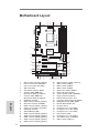
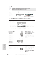
Motherboard Layout
1 ATX 12V Power Connector (ATX12V1) 20 SATA2 Connector (SATA2_1 (PORT 1))
2 Power Fan Connector (PWR_FAN1) 21 USB 2.0 Header (USB6_7)
3 CPU Fan Connector (CPU_FAN1) 22 USB 2.0 Header (USB4_5)
4 AM3+ CPU Socket 23 USB 2.0 Header (USB8_9)
5 CPU Heatsink Retention Module 24 System Panel Header (PANEL1)
6 2 x 240-pin DDR3 DIMM Slots 25 Power LED Header (PLED1)
(Dual Channel: DDR3_A1, DDR3_B1) 26 Chassis Speaker Header (SPEAKER1)
7 2 x 240-pin DDR3 DIMM Slots 27 Floppy Connector (FLOPPY1)
(Dual Channel: DDR3_A2, DDR3_B2) 28 Internal Audio Connector (CD1)
8 Northbridge Controller 29 Front Panel Audio Header (HD_AUDIO1)
9 SATA3 Connector (SATA3_2 (PORT 7)) 30 HDMI_SPDIF Header (HDMI_SPDIF1)
10 ATX Power Connector (ATXPWR1) 31 Infrared Module Header (IR1)
11 SATA3 Connector (SATA3_1 (PORT 6)) 32 PCI Slots (PCI1-2)
12 Chassis Fan Connector (CHA_FAN1) 33 PCI Express 2.0 x1 Slot (PCIE4)
13 Southbridge Controller 34 PCI Express 2.0 x16 Slot (PCIE3)
14 SPI Flash Memory (16Mb) 35 PCI Express 2.0 x1 Slot (PCIE2)
15 SATA2 Connector (SATA2_6 (PORT 5)) 36 IDE1 Connector (IDE1)
16 SATA2 Connector (SATA2_5 (PORT 4)) 37 PCI Express 2.0 x1 Slot (PCIE1)
17 SATA2 Connector (SATA2_4 (PORT 3)) 38 Clear CMOS Jumper (CLRCMOS1)
18 SATA2 Connector (SATA2_3 (PORT 2)) 39 USB 3.0 Header (USB3_2_3)
19 SATA2 Connector (SATA2_2 (PORT 1))
6
7
1
2
4
3
5
8
9
10
11
12
13
14
15
16
17
18
19
20
21
22
23
24
25
26
27
28
29
30
31
32
33
34
35
IDE 1
AMD
SB710
Chipset
ATX12 V1
8Mb
BIOS
CM OS
BA TT ERY
CLR CMOS 1
1
LAN
PHY
AUD IO
COD EC
Super
I/O
IR1
1
CD1
HD_A UDIO 1
1
PCIE1
FLOP PY1
HDLED RE SET
PLED PWRB TN
1
PANEL 1
SPEA KER1
1
SATAII _2(PO RT 1)
AMD
770
Chipset
PCI1
PCI2
980DE3/U3S3
SATAII _4(PO RT 3)
SATAII _3(PO RT 2)
Top:
LIN E I N
Cen ter :
FRO NT
Bot tom :
MIC IN
PS2
Mouse
PS2
Keyb oa rd
USB 2.0
T: USB0
B: USB1
Top:
RJ-45
USB 3.0
T: U SB 0
B: USB1
Front USB 3.0
ErP/EuP Ready
RoHS
USB 8_9
1
SATAII _1(PO RT 0)
SATAII _6(PO RT 5)
SATAII _5(PO RT 4)
1
PLED 1
1
HDMI _SPD IF1
USB 6_7
1
USB 4_5
1
USB 2.0
T: U SB 2
B: USB3
COM1
CHA _FAN1
Support 8-Core CPU
36
37
38
SOCKET AM3b
PCIE2
PCIE4
PCIE3
FSB8 00
DDR3 _A1 ( 6 4 bi t, 240-p in module)
DDR3 _A2 ( 6 4 bi t, 240-p in module)
FSB8 00
DDR3 _B1 ( 6 4 bi t, 240-p in module)
DDR3 _B2 ( 6 4 bi t, 240-p in module)
SATA3_ 2(POR T 7)
SATA3_ 1(POR T 6)
DDR3 1866
AM3+
140W CPU
CPU _FAN1PWR _FAN1
X
Fast RAM
X
Fast LAN
USB 3_2 _3
39

3
ASRock 980DE3/U3S3 R2.0 Motherboard
English
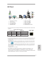
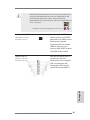
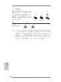
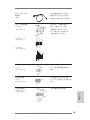
I/O Panel
LAN Port
ACT/LINK
LED
SPEED
LED
* There are two LED next to the LAN port. Please refer to the table below for the LAN port LED
indications.
LAN Port LED Indications
Activity/Link LED SPEED LED
Status Description Status Description
Off No Link Off 10Mbps connection
Blinking Data Activity Orange 100Mbps connection
On Link Green 1Gbps connection
1 PS/2 Mouse Port (Green) 6 USB 2.0 Ports (USB01)
* 2 LAN RJ-45 Port 7 USB 3.0 Port (USB01)
3 Line In (Light Blue) 8 USB 2.0 Ports (USB23)
** 4 Front Speaker (Lime) 9 Serial Port: COM1
5 Microphone (Pink) 10 PS/2 Keyboard Port (Purple)
** To enable Multi-Streaming function, you need to connect a front panel audio cable to the front
panel audio header. Please refer to below steps for the software setting of Multi-Streaming.
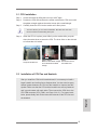
For Windows
®
XP:
After restarting your computer, you will nd “Mixer” tool on your system. Please select “Mixer
ToolBox” , click “Enable playback multi-streaming”, and click “ok”. Choose “2CH” or
“4CH” and then you are allowed to select “Realtek HDA Primary output” to use Rear Speaker
and Front Speaker, or select “Realtek HDA Audio 2nd output” to use front panel audio. Then
reboot your system.
For Windows
®
8.1 / 8 / 7 / Vista
TM
:
After restarting your computer, please double-click “Realtek HD Audio Manager” on the
system tray. Set “Speaker Conguration” to “Quadraphonic” or “Stereo”. Click “Device
advanced settings”, choose “Make front and rear output devices playbacks two different audio
streams simultaneously”, and click “ok”. Then reboot your system.
5
6
4
1
2
3
7
8
910

4
ASRock 980DE3/U3S3 R2.0 Motherboard
English
1. Introduction
Thank you for purchasing ASRock 980DE3/U3S3 R2.0 motherboard, a reliable
motherboard produced under ASRock’s consistently stringent quality control. It
delivers excellent performance with robust design conforming to ASRock’s commit-
ment to quality and endurance.
This Quick Installation Guide contains introduction of the motherboard and step-by-
step installation guide. More detailed information of the motherboard can be found
in the user manual presented in the Support CD.
Because the motherboard specications and the BIOS software might
be updated, the content of this manual will be subject to change without
notice. In case any modications of this manual occur, the updated ver-
sion will be available on ASRock website without further notice. You may
nd the latest VGA cards and CPU support lists on ASRock website as
well. ASRock website http://www.asrock.com
If you require technical support related to this motherboard, please visit
our website for specic information about the model you are using.
www.asrock.com/support/index.asp
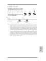
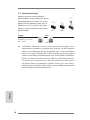
1.1 Package Contents
ASRock 980DE3/U3S3 R2.0 Motherboard (ATX Form Factor)
ASRock 980DE3/U3S3 R2.0 Quick Installation Guide
ASRock 980DE3/U3S3 R2.0 Support CD
2 x Serial ATA (SATA) Data Cables (Optional)
1 x I/O Panel Shield

5
ASRock 980DE3/U3S3 R2.0 Motherboard
English
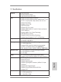
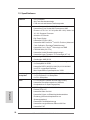
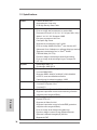
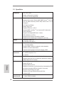
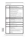
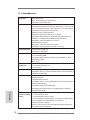
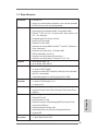
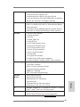
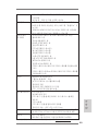
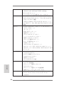
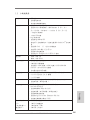
1.2 Specications
Platform - ATX Form Factor
- All Solid Capacitor design
- High Density Glass Fabric PCB
CPU - Support for Socket AM3+ Processors
- Support for Socket AM3 Processors: AMD Phenom
TM
II X6 /
X4 / X3 / X2 (except 920 / 940) / Athlon II X4 / X3 / X2 /
Sempron Processors
- Supports 8-Core CPU
- Digi Power design
- Supports CPU up to 140W
- Supports AMD OverDrive™ with ACC feature (Advanced
Clock Calibration)
- Supports AMD’s Cool ‘n’ Quiet Technology
- FSB 2600 MHz (5.2 GT/s)
- Supports Untied Overclocking Technology
- Supports Hyper-Transport 3.0 (HT 3.0) Technology
Chipset - Northbridge: AMD 770
- Southbridge: AMD SB710
Memory - Dual Channel DDR3 Memory Technology
- 4 x DDR3 DIMM Slots
- Supports DDR3 1866(OC)/1600(OC)/1333/1066/800
non-ECC, un-buffered memory (see CAUTION 1)
- Max. capacity of system memory: 32GB (see CAUTION 2)
Expansion Slot - 1 x PCI Express 2.0 x16 Slot (PCIE3 @ x16 mode)
- 3 x PCI Express 2.0 x1 Slots
- 2 x PCI Slots
Audio - 5.1 CH HD Audio (Realtek ALC662 Audio Codec)
- Supports Surge Protection (ASRock Full Spike Protection)
LAN - PCIE x1 Gigabit LAN 10/100/1000 Mb/s
- Realtek RTL8111E
- Supports Wake-On-LAN
- Supports Lightning/ESD Protection (ASRock Full Spike
Protection)
- Supports LAN Cable Detection
- Supports Energy Efcient Ethernet 802.3az
- Supports PXE
Rear Panel I/O - 1 x PS/2 Mouse Port
- 1 x PS/2 Keyboard Port
- 1 x Serial Port: COM1

6
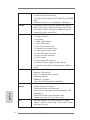
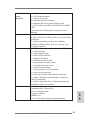
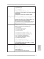
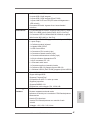
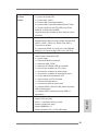
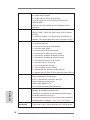
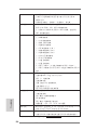
ASRock 980DE3/U3S3 R2.0 Motherboard
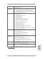
- 4 x USB 2.0 Ports
- 2 x USB 3.0 Ports (Etron EJ188)
- 1 x RJ-45 LAN Port with LED (ACT/LINK LED and SPEED
LED)
- HD Audio Jacks: Line in / Front Speaker / Microphone
Storage - 6 x SATA2 3.0 Gb/s Connectors, support RAID (RAID 0,
RAID 1, RAID 10 and JBOD), NCQ, AHCI and Hot Plug
- 2 x SATA3 6.0 Gb/s Connectors by ASMedia ASM1061,
support NCQ, AHCI and Hot Plug
Connector - 1 x ATA133 IDE Connector (Supports 2 x IDE Devices)
- 1 x Floppy Connector
- 1 x IR Header
- 1 x HDMI_SPDIF Header
- 1 x Power LED Header
- 1 x CPU Fan Connector (4-pin)
- 1 x Chassis Fan Connector (4-pin)
- 1 x Power Fan Connector (4-pin)
- 1 x 24 pin ATX Power Connector
- 1 x 8 pin 12V Power Connector
- 1 x CD In Header
- 1 x Front Panel Audio Connector
- 3 x USB 2.0 Headers (Support 6 USB 2.0 ports)
- 1 x USB 3.0 Header (Etron EJ188) (Supports 2 USB 3.0
ports)
BIOS Feature - 8Mb AMI Legal BIOS
- Supports “Plug and Play”
- ACPI 1.1 Compliant wake up events
- Supports jumperfree
- SMBIOS 2.3.1 Support
- CPU, VCCM, NB Voltage Multi-adjustment
Hardware - CPU temperature sensing
Monitor - Chassis temperature sensing
- CPU/Chassis/Power Fan Tachometer
- CPU Quiet Fan (Auto adjust chassis fan speed by CPU
temperature)
- CPU/Chassis/Power Fan multi-speed control
- Voltage monitoring: +12V, +5V, +3.3V, Vcore
OS - Microsoft
®
Windows
®
8.1 32-bit / 8.1 64-bit / 8 32-bit /
8 64-bit / 7 32-bit / 7 64-bit / Vista
TM
32-bit / Vista
TM
64-bit /
XP 32-bit / XP 64-bit
English

7
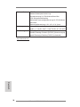
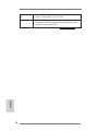
ASRock 980DE3/U3S3 R2.0 Motherboard
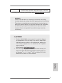
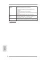
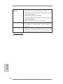
Certications - FCC, CE, WHQL
- ErP/EuP ready (ErP/EuP ready power supply is required)
* For detailed product information, please visit our website: http://www.asrock.com
CAUTION!
1. Whether 1866/1600MHz memory speed is supported depends
on the AM3/AM3+ CPU you adopt. If you want to adopt DDR3
1866/1600 memory module on this motherboard, please refer
to the memory support list on our website for the compatible
memory modules.
ASRock website: http://www.asrock.com
2. Due to the operating system limitation, the actual memory size
may be less than 4GB for the reservation for system usage un-
der Windows
®
8.1 / 8 / 7 / Vista
TM
/ XP. For Windows
®
64-bit OS
with 64-bit CPU, there is no such limitation.
WARNING
Please realize that there is a certain risk involved with overclocking,
including adjusting the setting in the BIOS, applying Untied Overclocking
Technology, or using third-party overclocking tools. Overclocking may
affect your system’s stability, or even cause damage to the components
and devices of your system. It should be done at your own risk and
expense. We are not responsible for possible damage caused by
overclocking.
English

8
ASRock 980DE3/U3S3 R2.0 Motherboard
English
2. Installation
This is an ATX form factor motherboard. Before you install the motherboard, study
the conguration of your chassis to ensure that the motherboard ts into it.
Pre-installation Precautions
Take note of the following precautions before you install motherboard
components or change any motherboard settings.
Before you install or remove any component, ensure that the
power is switched off or the power cord is detached from the
power supply. Failure to do so may cause severe damage to
the motherboard, peripherals, and/or components.
1. Unplug the power cord from the wall socket before touching any
component.
2. To avoid damaging the motherboard components due to static elec-
tricity, NEVER place your motherboard directly on the carpet or the
like. Also remember to use a grounded wrist strap or touch a safety
grounded object before you handle components.
3. Hold components by the edges and do not touch the ICs.
4. Whenever you uninstall any component, place it on a grounded
anti-static pad or in the bag that comes with the component.
5. When placing screws into the screw holes to secure the mother-
board to the chassis, please do not over-tighten the screws! Doing
so may damage the motherboard.

9
ASRock 980DE3/U3S3 R2.0 Motherboard
English
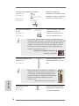
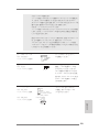
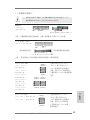
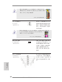
STEP 1:
Lift Up The Socket Lever
STEP 2 / STEP 3:
Match The CPU Golden Triangle
To The Socket Corner Small
Triangle
STEP 4:
Push Down And Lock
The Socket Lever
Lever 90° Up
CPU Golden Triangle
Socker Corner
Small Triangle
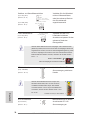
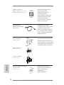
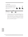
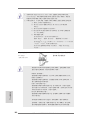
2.1 CPU Installation
Step 1. Unlock the socket by lifting the lever up to a 90
o
angle.
Step 2. Position the CPU directly above the socket such that the CPU corner with
the golden triangle matches the socket corner with a small triangle.
Step 3. Carefully insert the CPU into the socket until it ts in place.
The CPU ts only in one correct orientation. DO NOT force the CPU
into the socket to avoid bending of the pins.
Step 4. When the CPU is in place, press it rmly on the socket while you push
down the socket lever to secure the CPU. The lever clicks on the side tab
to indicate that it is locked.
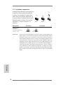
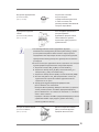
2.2 Installation of CPU Fan and Heatsink
After you install the CPU into this motherboard, it is necessary to install a
larger heatsink and cooling fan to dissipate heat. You also need to spray
thermal grease between the CPU and the heatsink to improve heat dis-
sipation. Make sure that the CPU and the heatsink are securely fastened
and in good contact with each other. Then connect the CPU fan to the
CPU FAN connector (CPU_FAN1, see Page 2, No. 3). For proper instal-
lation, please kindly refer to the instruction manuals of the CPU fan and
the heatsink.

10
ASRock 980DE3/U3S3 R2.0 Motherboard
English
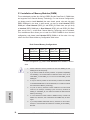
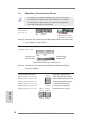
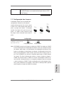
2.3 Installation of Memory Modules (DIMM)
This motherboard provides four 240-pin DDR3 (Double Data Rate 3) DIMM slots,
and supports Dual Channel Memory Technology. For dual channel conguration,
you always need to install identical (the same brand, speed, size and chip-type)
DDR3 DIMM pair in the slots. In other words, you have to install identical DDR3
DIMM pair in Dual Channel (DDR3_A1 and DDR3_B1; Black slots; see p.2 No.6)
or identical DDR3 DIMM pair in Dual Channel (DDR3_A2 and DDR3_B2; Black
slots; see p.2 No.7), so that Dual Channel Memory Technology can be activated.
This motherboard also allows you to install four DDR3 DIMMs for dual channel
conguration, and please install identical DDR3 DIMMs in all four slots. You may
refer to the Dual Channel Memory Conguration Table below.
Dual Channel Memory Congurations
DDR3_A1 DDR3_A2 DDR3_B1 DDR3_B2
(Black Slot) (Black Slot) (Black Slot) (Black Slot)
(1) Populated - Populated -
(2) - Populated - Populated
(3)* Populated Populated Populated Populated
*
For the conguration (3), please install identical DDR3 DIMMs in all four
slots.
1. Please install the memory module into the slots DDR3_A2 and
DDR3_B2 for the rst priority.
2. If you want to install two memory modules, for optimal compatibility
and reliability, it is recommended to install them either in the set of
slots DDR3_A1 and DDR3_B1, or in the set of slots DDR3_A2 and
DDR3_B2.
3. If only one memory module or three memory modules are installed
in the DDR3 DIMM slots on this motherboard, it is unable to activate
the Dual Channel Memory Technology.
4. If a pair of memory modules is NOT installed in the same Dual
Channel, for example, installing a pair of memory modules in
DDR3_A1 and DDR3_A2, it is unable to activate the Dual Channel
Memory Technology .
5. It is not allowed to install a DDR or DDR2 memory module into
DDR3 slot; otherwise, this motherboard and DIMM may be dam-
aged.
6. If you adopt DDR3 1866/1600 memory modules on this mother-
board, it is recommended to install them on DDR3_A2 and DDR3_
B2 slots.

11
ASRock 980DE3/U3S3 R2.0 Motherboard
English
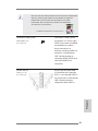
notch
break
notch
break
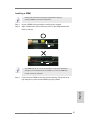
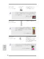
Installing a DIMM
Please make sure to disconnect power supply before adding or
removing DIMMs or the system components.
Step 1. Unlock a DIMM slot by pressing the retaining clips outward.
Step 2. Align a DIMM on the slot such that the notch on the DIMM matches the
break on the slot.
The DIMM only ts in one correct orientation. It will cause permanent
damage to the motherboard and the DIMM if you force the DIMM into
the slot at incorrect orientation.
Step 3. Firmly insert the DIMM into the slot until the retaining clips at both ends
fully snap back in place and the DIMM is properly seated.

12
ASRock 980DE3/U3S3 R2.0 Motherboard
English
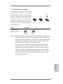
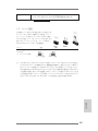
2.4 Expansion Slots (PCI and PCI Express Slots)
There are 2 PCI slots and 4 PCI Express slots on this motherboard.
PCI Slots: PCI slots are used to install expansion cards that have the 32-bit PCI
interface.
PCIE Slots:
PCIE1 / PCIE2 / PCIE4 (PCIE x1 slot; Black) is used for PCI Express
cards with x1 lane width cards, such as Gigabit LAN card and SATA2
card.
PCIE3 (PCIE x16 slot; Black) is used for PCI Express x16 lane width
graphics cards.
Installing an expansion card
Step 1. Before installing the expansion card, please make sure that the power
supply is switched off or the power cord is unplugged. Please read the
documentation of the expansion card and make necessary hardware
settings for the card before you start the installation.
Step 2. Remove the system unit cover (if your motherboard is already installed
in a chassis).
Step 3. Remove the bracket facing the slot that you intend to use. Keep the
screws for later use.
Step 4. Align the card connector with the slot and press rmly until the card is
completely seated on the slot.
Step 5. Fasten the card to the chassis with screws.
Step 6. Replace the system cover.

13
ASRock 980DE3/U3S3 R2.0 Motherboard
English
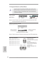
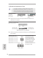
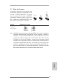
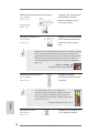
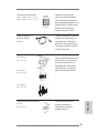
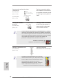
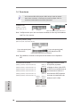
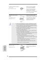
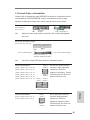
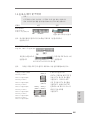
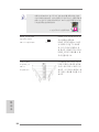
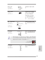
2.5 Jumpers Setup
The illustration shows how jumpers are
setup. When the jumper cap is placed on
pins, the jumper is “Short”. If no jumper cap
is placed on pins, the jumper is “Open”. The
illustration shows a 3-pin jumper whose
pin1 and pin2 are “Short” when jumper cap
is placed on these 2 pins.
Jumper Setting Description
Clear CMOS Jumper
(CLRCMOS1)
(see p.2, No. 38)
Note: CLRCMOS1 allows you to clear the data in CMOS. To clear and reset the
system parameters to default setup, please turn off the computer and unplug
the power cord from the power supply. After waiting for 15 seconds, use a
jumper cap to short pin2 and pin3 on CLRCMOS1 for 5 seconds. However,
please do not clear the CMOS right after you update the BIOS. If you need
to clear the CMOS when you just nish updating the BIOS, you must boot
up the system rst, and then shut it down before you do the clear-CMOS ac-
tion. Please be noted that the password, date, time, user default prole, 1394
GUID and MAC address will be cleared only if the CMOS battery is removed.
Clear CMOSDefault

14
ASRock 980DE3/U3S3 R2.0 Motherboard
English
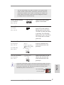
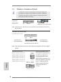
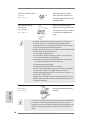
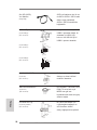
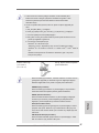
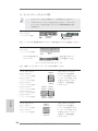
2.6 Onboard Headers and Connectors
Onboard headers and connectors are NOT jumpers. Do NOT place
jumper caps over these headers and connectors. Placing jumper caps
over the headers and connectors will cause permanent damage of the
motherboard!
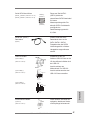
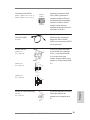
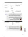
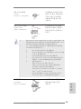
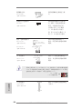
Serial ATA3 Connectors These two Serial ATA3
(SATA3_1 (PORT 6): see p.2, No. 11)
(SATA3) connectors support
(SATA3_2 (PORT 7): see p.2, No. 9)
SATA data cables for internal
storage devices. The current
SATA3 interface allows up to
6.0 Gb/s data transfer rate.
FDD connector
(33-pin FLOPPY1)
(see p.2 No. 27)
Note: Make sure the red-striped side of the cable is plugged into Pin1 side of the
connector.
the red-striped side to Pin1
Primary IDE connector (Black)
(39-pin IDE1, see p.2 No. 36)
Note: Please refer to the instruction of your IDE device vendor for the details.
connect the black end
to the IDE devices
connect the blue end
to the motherboard
80-conductor ATA 66/100/133 cable
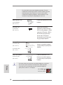
Serial ATA2 Connectors These six Serial ATA2 (SATA2)
(SATAII_1 (PORT 0): see p.2, No. 20)
connectors support SATA data
(SATAII_2 (PORT 1): see p.2, No. 19)
cables for internal storage
(SATAII_3 (PORT 2): see p.2, No. 18)
devices. The current SATA2
(SATAII_4 (PORT 3): see p.2, No. 17)
interface allows up to 3.0 Gb/s
(SATAII_5 (PORT 4): see p.2, No. 16)
data transfer rate.
(SATAII_6 (PORT 5): see p.2, No. 15)
SATAII_1 SATAII_3
(PORT 0) (PORT 2)
SATAII_2 SATAII_4
(PORT 1) (PORT 3)
SATAII_5
(PORT 4)
SATAII_6
(PORT 5)
SATA3_1
(PORT 6)
SATA3_2
(PORT 7)

15
ASRock 980DE3/U3S3 R2.0 Motherboard
English
1
USB_ PWR
P-8
GND
DUMMY
USB_ PWR
P+8
GND
P-9
P+9
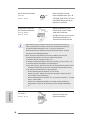
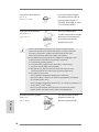
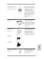
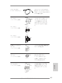
USB 2.0 Headers Besides four default USB 2.0
(9-pin USB4_5)
ports on the I/O panel, there
(see p.2 No. 22)
are three USB 2.0 headers on
this motherboard. Each USB 2.0
header can support two USB
2.0 ports.
(9-pin USB6_7)
(see p.2 No. 21)
(9-pin USB8_9)
(see p.2 No. 23)
P- 7
P+ 7
GND
DUMMY
USB_PWR
USB_PWR
P- 6
P+ 6
GND
1
Infrared Module Header This header supports an
(5-pin IR1)
optional wireless transmitting
(see p.2 No. 31)
and receiving infrared module.
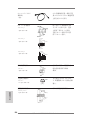
Serial ATA (SATA) Either end of the SATA data
Data Cable cable can be connected to the
(Optional)
SATA / SATA2 / SATA3 hard
disk or the SATA3 connector on
this motherboard.
Internal Audio Connectors This connector allows you to
(4-pin CD1)
receive stereo audio input from
(CD1: see p.2 No. 28)
sound sources such as a
CD-ROM, DVD-ROM, TV tuner
card, or MPEG card.
Front Panel Audio Header This is an interface for the front
(9-pin HD_AUDIO1)
panel audio cable that allows
(see p.2 No. 29)
convenient connection and
control of audio devices.
J_SE NSE
OUT2 _L
1
MIC_ RET
PRES ENCE#
GND
OUT2 _R
MIC2 _R
MIC2 _L
OUT_RET
CD-L
GND
GND
CD-R
CD1

16
ASRock 980DE3/U3S3 R2.0 Motherboard
English
1. High Denition Audio supports Jack Sensing, but the panel wire on
the chassis must support HDA to function correctly. Please follow the
instruction in our manual and chassis manual to install your system.
2. If you use AC’97 audio panel, please install it to the front panel audio
header as below:
A. Connect Mic_IN (MIC) to MIC2_L.
B. Connect Audio_R (RIN) to OUT2_R and Audio_L (LIN) to OUT2_L.
C. Connect Ground (GND) to Ground (GND).
D. MIC_RET and OUT_RET are for HD audio panel only. You don’t
need to connect them for AC’97 audio panel.
E. To activate the front mic.
For Windows
®
XP / XP 64-bit OS:
Select “Mixer”. Select “Recorder”. Then click “FrontMic”.
For Windows
®
8.1 / 8.1 64-bit / 8 / 8 64-bit / 7 / 7 64-bit / Vista
TM
/
Vista
TM
64-bit OS:
Go to the "FrontMic" Tab in the Realtek Control panel. Adjust
“Recording Volume”.
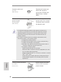
System Panel Header This header accommodates
(9-pin PANEL1)
several system front panel
(see p.2 No. 24)
functions.
Connect the power switch, reset switch and system status indicator
on the chassis to this header according to the pin assignments below.
Note the positive and negative pins before connecting the cables.
PWRBTN (Power Switch):
Connect to the power switch on the chassis front panel. You may con-
gure the way to turn off your system using the power switch.
RESET (Reset Switch):
Connect to the reset switch on the chassis front panel. Press the reset
switch to restart the computer if the computer freezes and fails to per-
form a normal restart.
PLED (System Power LED):
Connect to the power status indicator on the chassis front panel. The
LED is on when the system is operating. The LED keeps blinking
when the sys-tem is in S1 sleep state. The LED is off when the system
is in S3/S4 sleep state or powered off (S5).
HDLED (Hard Drive Activity LED):
Connect to the hard drive activity LED on the chassis front panel. The
LED is on when the hard drive is reading or writing data.
GND
RES ET#
PWR BTN#
PLE D-
PLE D+
GND
HDL ED-
HDL ED+
1
GND

17
ASRock 980DE3/U3S3 R2.0 Motherboard
English
The front panel design may differ by chassis. A front panel module
mainly consists of power switch, reset switch, power LED, hard drive
activity LED, speaker and etc. When connecting your chassis front
panel module to this header, make sure the wire assignments and the
pin assign-ments are matched correctly.
Power LED Header Please connect the chassis
(3-pin PLED1)
power LED to this header to
(see p.2 No. 25)
indicate system power status.
The LED is on when the system
is operating. The LED keeps
blinking in S1 state. The LED is
off in S3/S4 state or S5 state
(power off).
Chassis Speaker Header Please connect the chassis
(4-pin SPEAKER 1)
speaker to this header.
(see p.2 No. 26)
1
+5V
DUMMY
DUMMY
SPEAKER
1
PLED+
PLED+
PLED-
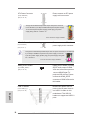
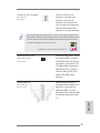
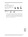
Chassis and Power Fan Connectors Please connect the fan cables
(4-pin CHA_FAN1)
to the fan connectors and
(see p.2 No. 12)
match the black wire to the
ground pin.
(4-pin PWR_FAN1)
(see p.2 No. 2)
CPU Fan Connectors Please connect the CPU fan
(4-pin CPU_FAN1)
cable to the connector and
(see p.2 No. 3)
match the black wire to the
ground pin.
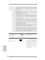
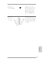
Though this motherboard provides 4-Pin CPU fan (Quiet Fan) support, the 3-Pin
CPU fan still can work successfully even without the fan speed control function.
If you plan to connect the 3-Pin CPU fan to the CPU fan connector on this
motherboard, please connect it to Pin 1-3.
Pin 1-3 Connected
3-Pin Fan Installation
GND
+12V
CPU_FAN_SPEED
FAN_SPEE D_CONTROL
1 2 3 4
GND
+12V
PWR_FAN_SPEED
FAN_SPEED_CONTROL

18
ASRock 980DE3/U3S3 R2.0 Motherboard
English
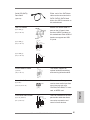
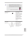
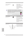
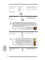
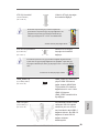
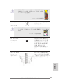
ATX Power Connector Please connect an ATX power
(24-pin ATXPWR1)
supply to this connector.
(see p.2 No. 10)
12
1
Though this motherboard provides 24-pin ATX power connector,
it can still work if you adopt a traditional 20-pin ATX power supply.
To use the 20-pin ATX power supply, please plug your power
supply along with Pin 1 and Pin 13.
ATX 12V Power Connector Please connect an ATX 12V
(8-pin ATX12V1)
power supply to this connector.
(see p.2 No. 1)
Though this motherboard provides 8-pin ATX 12V power connector, it can still work
if you adopt a traditional 4-pin ATX 12V power supply. To use the
4-pin ATX power supply, please plug your power supply along with
Pin 1 and Pin 5.
20-Pin ATX Power Supply Installation
4-Pin ATX 12V Power Supply Installation
12
1
24
13
24
13
5 1
8 4
5 1
8 4
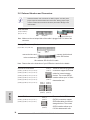
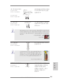
HDMI_SPDIF Header HDMI_SPDIF header, providing
(2-pin HDMI_SPDIF1)
SPDIF audio output to HDMI
(
see p.2 No. 30)
VGA card, allows the system to
connect HDMI Digital TV/
projector/LCD devices. Please
connect the HDMI_SPDIF
connector of HDMI VGA card to
this header.
SPDIFOUT
GND
1
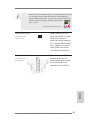
USB 3.0 Header Besides two default USB 3.0
(19-pin USB3_2_3)
ports on the I/O panel, there is
(see p.2 No. 39)
one USB 3.0 header on this
motherboard. This USB 3.0
header can support two USB 3.0
ports.

19
ASRock 980DE3/U3S3 R2.0 Motherboard
English
2.7 Untied Overclocking Technology
This motherboard supports Untied Overclocking Technology, which means during
overclocking, FSB enjoys better margin due to xed PCI / PCIE buses. Before you
enable Untied Overclocking function, please enter “Overclock Mode” option of BIOS
setup to set the selection from [Auto] to [Manual]. Therefore, CPU FSB is untied
during overclocking, but PCI / PCIE buses are in the xed mode so that FSB can
operate under a more stable overclocking environment.
Please refer to the warning on page 7 for the possible overclocking risk
before you apply Untied Overclocking Technology.

20
ASRock 980DE3/U3S3 R2.0 Motherboard
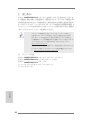
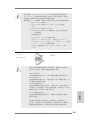
3. BIOS Information
The Flash Memory on the motherboard stores BIOS Setup Utility. When you start up
the computer, please press <F2> or <Del> during the Power-On-Self-Test (POST)
to enter BIOS Setup utility; otherwise, POST continues with its test routines. If you
wish to enter BIOS Setup after POST, please restart the system by pressing <Ctl>
+ <Alt> + <Delete>, or pressing the reset button on the system chassis. The BIOS
Setup program is designed to be user-friendly. It is a menu-driven program, which
allows you to scroll through its various sub-menus and to select among the prede-
termined choices. For the detailed information about BIOS Setup, please refer to the
User Manual (PDF le) contained in the Support CD.
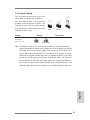
4. Software Support CD information
This motherboard supports various Microsoft
®
Windows
®
operating systems: 8.1 / 8.1
64-bit / 8 / 8 64-bit / 7 / 7 64-bit / Vista
TM
/ Vista
TM
64-bit / XP / XP 64-bit. The Support
CD that came with the motherboard contains necessary drivers and useful utilities
that will enhance motherboard features. To begin using the Support CD, insert the
CD into your CD-ROM drive. It will display the Main Menu automatically if “AUTO-
RUN” is enabled in your computer. If the Main Menu does not appear automatically,
locate and double-click on the le “ASRSETUP.EXE” from the BIN folder in the Sup-
port CD to display the menus.
English
Sayfa yükleniyor...
Sayfa yükleniyor...
Sayfa yükleniyor...
Sayfa yükleniyor...
Sayfa yükleniyor...
Sayfa yükleniyor...
Sayfa yükleniyor...
Sayfa yükleniyor...
Sayfa yükleniyor...
Sayfa yükleniyor...
Sayfa yükleniyor...
Sayfa yükleniyor...
Sayfa yükleniyor...
Sayfa yükleniyor...
Sayfa yükleniyor...
Sayfa yükleniyor...
Sayfa yükleniyor...
Sayfa yükleniyor...
Sayfa yükleniyor...
Sayfa yükleniyor...
Sayfa yükleniyor...
Sayfa yükleniyor...
Sayfa yükleniyor...
Sayfa yükleniyor...
Sayfa yükleniyor...
Sayfa yükleniyor...
Sayfa yükleniyor...
Sayfa yükleniyor...
Sayfa yükleniyor...
Sayfa yükleniyor...
Sayfa yükleniyor...
Sayfa yükleniyor...
Sayfa yükleniyor...
Sayfa yükleniyor...
Sayfa yükleniyor...
Sayfa yükleniyor...
Sayfa yükleniyor...
Sayfa yükleniyor...
Sayfa yükleniyor...
Sayfa yükleniyor...
Sayfa yükleniyor...
Sayfa yükleniyor...
Sayfa yükleniyor...
Sayfa yükleniyor...
Sayfa yükleniyor...
Sayfa yükleniyor...
Sayfa yükleniyor...
Sayfa yükleniyor...
Sayfa yükleniyor...
Sayfa yükleniyor...
Sayfa yükleniyor...
Sayfa yükleniyor...
Sayfa yükleniyor...
Sayfa yükleniyor...
Sayfa yükleniyor...
Sayfa yükleniyor...
Sayfa yükleniyor...
Sayfa yükleniyor...
Sayfa yükleniyor...
Sayfa yükleniyor...
Sayfa yükleniyor...
Sayfa yükleniyor...
Sayfa yükleniyor...
Sayfa yükleniyor...
Sayfa yükleniyor...
Sayfa yükleniyor...
Sayfa yükleniyor...
Sayfa yükleniyor...
Sayfa yükleniyor...
Sayfa yükleniyor...
Sayfa yükleniyor...
Sayfa yükleniyor...
Sayfa yükleniyor...
Sayfa yükleniyor...
Sayfa yükleniyor...
Sayfa yükleniyor...
Sayfa yükleniyor...
Sayfa yükleniyor...
Sayfa yükleniyor...
Sayfa yükleniyor...
Sayfa yükleniyor...
Sayfa yükleniyor...
Sayfa yükleniyor...
Sayfa yükleniyor...
Sayfa yükleniyor...
Sayfa yükleniyor...
Sayfa yükleniyor...
Sayfa yükleniyor...
Sayfa yükleniyor...
Sayfa yükleniyor...
Sayfa yükleniyor...
Sayfa yükleniyor...
Sayfa yükleniyor...
Sayfa yükleniyor...
Sayfa yükleniyor...
Sayfa yükleniyor...
Sayfa yükleniyor...
Sayfa yükleniyor...
Sayfa yükleniyor...
Sayfa yükleniyor...
Sayfa yükleniyor...
Sayfa yükleniyor...
Sayfa yükleniyor...
Sayfa yükleniyor...
Sayfa yükleniyor...
Sayfa yükleniyor...
Sayfa yükleniyor...
Sayfa yükleniyor...
Sayfa yükleniyor...
Sayfa yükleniyor...
Sayfa yükleniyor...
Sayfa yükleniyor...
Sayfa yükleniyor...
Sayfa yükleniyor...
Sayfa yükleniyor...
Sayfa yükleniyor...
Sayfa yükleniyor...
Sayfa yükleniyor...
Sayfa yükleniyor...
Sayfa yükleniyor...
Sayfa yükleniyor...
Sayfa yükleniyor...
Sayfa yükleniyor...
Sayfa yükleniyor...
Sayfa yükleniyor...
Sayfa yükleniyor...
Sayfa yükleniyor...
-
 1
1
-
 2
2
-
 3
3
-
 4
4
-
 5
5
-
 6
6
-
 7
7
-
 8
8
-
 9
9
-
 10
10
-
 11
11
-
 12
12
-
 13
13
-
 14
14
-
 15
15
-
 16
16
-
 17
17
-
 18
18
-
 19
19
-
 20
20
-
 21
21
-
 22
22
-
 23
23
-
 24
24
-
 25
25
-
 26
26
-
 27
27
-
 28
28
-
 29
29
-
 30
30
-
 31
31
-
 32
32
-
 33
33
-
 34
34
-
 35
35
-
 36
36
-
 37
37
-
 38
38
-
 39
39
-
 40
40
-
 41
41
-
 42
42
-
 43
43
-
 44
44
-
 45
45
-
 46
46
-
 47
47
-
 48
48
-
 49
49
-
 50
50
-
 51
51
-
 52
52
-
 53
53
-
 54
54
-
 55
55
-
 56
56
-
 57
57
-
 58
58
-
 59
59
-
 60
60
-
 61
61
-
 62
62
-
 63
63
-
 64
64
-
 65
65
-
 66
66
-
 67
67
-
 68
68
-
 69
69
-
 70
70
-
 71
71
-
 72
72
-
 73
73
-
 74
74
-
 75
75
-
 76
76
-
 77
77
-
 78
78
-
 79
79
-
 80
80
-
 81
81
-
 82
82
-
 83
83
-
 84
84
-
 85
85
-
 86
86
-
 87
87
-
 88
88
-
 89
89
-
 90
90
-
 91
91
-
 92
92
-
 93
93
-
 94
94
-
 95
95
-
 96
96
-
 97
97
-
 98
98
-
 99
99
-
 100
100
-
 101
101
-
 102
102
-
 103
103
-
 104
104
-
 105
105
-
 106
106
-
 107
107
-
 108
108
-
 109
109
-
 110
110
-
 111
111
-
 112
112
-
 113
113
-
 114
114
-
 115
115
-
 116
116
-
 117
117
-
 118
118
-
 119
119
-
 120
120
-
 121
121
-
 122
122
-
 123
123
-
 124
124
-
 125
125
-
 126
126
-
 127
127
-
 128
128
-
 129
129
-
 130
130
-
 131
131
-
 132
132
-
 133
133
-
 134
134
-
 135
135
-
 136
136
-
 137
137
-
 138
138
-
 139
139
-
 140
140
-
 141
141
-
 142
142
-
 143
143
-
 144
144
-
 145
145
-
 146
146
-
 147
147


ASROCK 980DE3/U3S3 Kullanım kılavuzu
- Kategori
- Anakartlar
- Tip
- Kullanım kılavuzu
diğer dillerde
- español: ASROCK 980DE3/U3S3 Manual de usuario
- français: ASROCK 980DE3/U3S3 Manuel utilisateur
- italiano: ASROCK 980DE3/U3S3 Manuale utente
- 日本語: ASROCK 980DE3/U3S3 ユーザーマニュアル
- Deutsch: ASROCK 980DE3/U3S3 Benutzerhandbuch
- português: ASROCK 980DE3/U3S3 Manual do usuário
- English: ASROCK 980DE3/U3S3 User manual
- русский: ASROCK 980DE3/U3S3 Руководство пользователя
İlgili makaleler
-
ASROCK 970 Extreme3 R2.0 Quick Installation Manual
-
-
-
ASROCK A55iCafe Hızlı başlangıç Kılavuzu
-
-
-
ASROCK E35LM1 R2.0 Hızlı başlangıç Kılavuzu
-
-
ASROCK 990FX Extreme4 Hızlı başlangıç Kılavuzu
-
ASROCK 970 Extreme4 Hızlı başlangıç Kılavuzu