
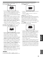
YAMAHA ELECTRONICS CORPORATION, USA
6660 ORANGETHORPE AVE., BUENA PARK, CALIF. 90620, U.S.A.
YAMAHA CANADA MUSIC LTD.
135 MILNER AVE., SCARBOROUGH, ONTARIO M1S 3R1, CANADA
YAMAHA ELECTRONIK EUROPA G.m.b.H.
SIEMENSSTR. 22-34, 25462 RELLINGEN BEI HAMBURG, F.R. OF GERMANY
YAMAHA ELECTRONIQUE FRANCE S.A.
RUE AMBROISE CROIZAT BP70 CROISSY-BEAUBOURG 77312 MARNE-LA-VALLEE CEDEX02, FRANCE
YAMAHA ELECTRONICS (UK) LTD.
YAMAHA HOUSE, 200 RICKMANSWORTH ROAD WATFORD, HERTS WD18 7GQ, ENGLAND
YAMAHA SCANDINAVIA A.B.
J A WETTERGRENS GATA 1, BOX 30053, 400 43 VÄSTRA FRÖLUNDA, SWEDEN
YAMAHA MUSIC AUSTRALIA PTY, LTD.
17-33 MARKET ST., SOUTH MELBOURNE, 3205 VIC., AUSTRALIA
©
2004 All rights reserved.
Printed in Malaysia WD64200
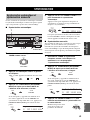
RX-V1500
AV Receiver
Ampli-tuner audio-vidéo
OWNER'S MANUAL
MODE D'EMPLOI
BEDIENUNGSANLEITUNG
BRUKSANVISNING
MANUALE DI ISTRUZIONI
MANUAL DE INSTRUCCIONES
GEBRUIKSAANWIJZING
GB
RX-V1500

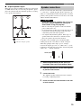
CAUTION: READ THIS BEFORE OPERATING YOUR UNIT.
1 To assure the finest performance, please read this manual
carefully. Keep it in a safe place for future reference.
2 Install this sound system in a well ventilated, cool, dry, clean
place — away from direct sunlight, heat sources, vibration,
dust, moisture, and/or cold. Allow ventilation space of at least
30 cm on the top, 20 cm on the left and right, and 20 cm on
the back of this unit.
3 Locate this unit away from other electrical appliances, motors,
or transformers to avoid humming sounds.
4 Do not expose this unit to sudden temperature changes from
cold to hot, and do not locate this unit in an environment with
high humidity (i.e. a room with a humidifier) to prevent
condensation inside this unit, which may cause an electrical
shock, fire, damage to this unit, and/or personal injury.
5 Avoid installing this unit where foreign object may fall onto
this unit and/or this unit may be exposed to liquid dripping or
splashing. On the top of this unit, do not place:
– Other components, as they may cause damage and/or
discoloration on the surface of this unit.
– Burning objects (i.e. candles), as they may cause fire,
damage to this unit, and/or personal injury.
– Containers with liquid in them, as they may fall and liquid
may cause electrical shock to the user and/or damage to
this unit.
6 Do not cover this unit with a newspaper, tablecloth, curtain,
etc. in order not to obstruct heat radiation. If the temperature
inside this unit rises, it may cause fire, damage to this unit,
and/or personal injury.
7 Do not plug in this unit to a wall outlet until all connections
are complete.
8 Do not operate this unit upside-down. It may overheat,
possibly causing damage.
9 Do not use force on switches, knobs and/or cords.
10 When disconnecting the power cord from the wall outlet,
grasp the plug; do not pull the cord.
11 Do not clean this unit with chemical solvents; this might
damage the finish. Use a clean, dry cloth.
12 Only voltage specified on this unit must be used. Using this
unit with a higher voltage than specified is dangerous and may
cause fire, damage to this unit, and/or personal injury.
YAMAHA will not be held responsible for any damage
resulting from use of this unit with a voltage other than
specified.
13 To prevent damage by lightning, disconnect the power cord
from the wall outlet during an electrical storm.
14 Do not attempt to modify or fix this unit. Contact qualified
YAMAHA service personnel when any service is needed. The
cabinet should never be opened for any reasons.
15 When not planning to use this unit for long periods of time
(i.e. vacation), disconnect the AC power plug from the wall
outlet.
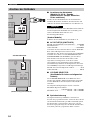
16 Be sure to read the “TROUBLESHOOTING” section on
common operating errors before concluding that this unit is
faulty.
17 Before moving this unit, press STANDBY/ON to set this unit
in the standby mode, and disconnect the AC power plug from
the wall outlet.
18 VOLTAGE SELECTOR (Asia and General models only)
The VOLTAGE SELECTOR on the rear panel of this unit
must be set for your local main voltage BEFORE plugging
into the AC main supply. Voltages are:
General model............. AC 110/120/220/230-240 V, 50/60 Hz
Asia model ..................................AC 220/230-240V, 50/60 Hz
■ For U.K. customers
If the socket outlets in the home are not suitable for the
plug supplied with this appliance, it should be cut off and
an appropriate 3 pin plug fitted. For details, refer to the
instructions described below.
The plug severed from the mains lead must be destroyed, as a
plug with bared flexible cord is hazardous if engaged in a live
socket outlet.
■ Special Instructions for U.K. Model
CAUTION: READ THIS BEFORE OPERATING YOUR UNIT.
WARNING
TO REDUCE THE RISK OF FIRE OR ELECTRIC
SHOCK, DO NOT EXPOSE THIS UNIT TO RAIN
OR MOISTURE.
This unit is not disconnected from the AC power
source as long as it is connected to the wall outlet, even
if this unit itself is turned off. This state is called the
standby mode. In this state, this unit is designed to
consume a very small quantity of power.
Note
IMPORTANT
THE WIRES IN MAINS LEAD ARE COLOURED IN
ACCORDANCE WITH THE FOLLOWING CODE:
Blue: NEUTRAL
Brown: LIVE
As the colours of the wires in the mains lead of this
apparatus may not correspond with the coloured
markings identifying the terminals in your plug,
proceed as follows:
The wire which is coloured BLUE must be connected
to the terminal which is marked with the letter N or
coloured BLACK. The wire which is coloured
BROWN must be connected to the terminal which is
marked with the letter L or coloured RED.
Making sure that neither core is connected to the earth
terminal of the three pin plug.

1
English
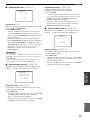
PREPARATIONINTRODUCTION
BASIC
OPERATION
ADVANCED
OPERATION
ADDITIONAL
INFORMATION
SOUND FIELD
PROGRAMS
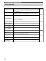
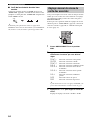
FEATURES............................................................. 2
GETTING STARTED............................................ 3
Supplied accessories .................................................. 3
Installing batteries in the remote control ................... 3
CONTROLS AND FUNCTIONS ......................... 4
Front panel ................................................................. 4
Remote control........................................................... 6
Using the remote control ........................................... 8
Front panel display .................................................... 9
Rear panel ................................................................ 11
SPEAKER SETUP ............................................... 12
Speaker placement ................................................... 12
Speaker connections ................................................ 13
CONNECTIONS .................................................. 17
Before connecting components................................ 17
Connecting video components................................. 18
Connecting audio components................................. 21
Connecting the antennas.......................................... 23
Connecting the power supply cord .......................... 24
Speaker impedance setting ...................................... 25
Turning on the power............................................... 25
AUTO SETUP....................................................... 26
Introduction.............................................................. 26
Optimizer microphone setup.................................... 26
Starting the setup ..................................................... 27
BASIC SETUP ...................................................... 31
Using BASIC MENU .............................................. 31
PLAYBACK.......................................................... 33
Basic operations....................................................... 33
Selecting sound field programs ............................... 34
Additional operations............................................... 35
Selecting input modes.............................................. 40
TUNING ................................................................ 41
Automatic and manual tuning.................................. 41
Presetting stations .................................................... 42
Selecting preset stations........................................... 44
Exchanging preset stations ...................................... 44
Receiving RDS stations ........................................... 45
Changing the RDS mode ......................................... 45
PTY SEEK function ................................................ 46
EON function........................................................... 47
RECORDING ....................................................... 48
SOUND FIELD PROGRAM
DESCRIPTIONS...............................................49
For movie/video sources.......................................... 49
For music sources .................................................... 52
ADVANCED OPERATIONS ..............................53
Selecting the OSD mode.......................................... 53
Using the sleep timer ............................................... 53
Manually adjusting speaker levels........................... 54
Using the test tone ................................................... 55
SET MENU ............................................................56
Using SET MENU................................................... 57
Using SOUND MENU ............................................ 58
Using INPUT MENU .............................................. 63
Using OPTION MENU ........................................... 65
REMOTE CONTROL FEATURES ...................68
Control area ............................................................. 68
Setting remote control codes ................................... 69
Programming codes from other remote controls
(Learn) ................................................................. 71
Changing source names in the display window....... 73
Using the Macro feature .......................................... 74
Clearing function sets .............................................. 76
Clearing individual functions .................................. 77
Controlling each component.................................... 79
ZONE 2/ZONE 3
(U.S.A., CANADA, U.K., EUROPE AND
AUSTRALIA MODELS ONLY).....................80
Zone 2/Zone 3 connections...................................... 80
Remote controlling Zone 2/Zone 3.......................... 81
EDITING SOUND FIELD PARAMETERS ......83
What is a sound field? ............................................. 83
Changing parameter settings ................................... 83
SOUND FIELD PARAMETER
DESCRIPTIONS...............................................85
TROUBLESHOOTING .......................................89
GLOSSARY...........................................................94
Audio formats .......................................................... 94
Sound field programs............................................... 95
Audio information ................................................... 96
Video signal information ......................................... 97
SPECIFICATIONS...............................................98
CONTENTS
INTRODUCTION
PREPARATION
BASIC OPERATION
SOUND FIELD PROGRAMS
ADVANCED OPERATION
ADDITIONAL INFORMATION

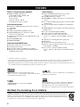
FEATURES
2
Built-in 7-channel power amplifier
◆ Minimum RMS output power
(0.04% THD, 20 Hz – 20 kHz, 8 Ω)
Front: 120 W + 120 W
Center: 120 W
Surround: 120 W + 120 W
Surround Back: 120 W + 120 W
Sound field features
◆ Proprietary YAMAHA technology for the creation of
sound fields
◆ THX Select
◆ Dolby Digital/Dolby Digital EX decoder
◆ DTS/DTS-ES Matrix 6.1, Discrete 6.1, DTS
Neo:6 decoder, DTS 96/24
◆ Dolby Pro Logic/Dolby Pro Logic II/Dolby Pro Logic
IIx Decoder
◆ Virtual CINEMA DSP
◆ SILENT CINEMA
™
Sophisticated AM/FM tuner
◆ 40-station random access preset tuning
◆ Automatic preset tuning
◆ Preset station shifting capability (preset editing)
◆ RDS: Radio Data System receiving capability (U.K.
and Europe models only)
Other features
◆ YPAO: YAMAHA Parametric Room Acoustic
Optimizer for automatic speaker setup
◆ 192-kHz/24-bit D/A converter
◆ SET MENU to optimize this unit for your audio/video
system
◆ 6 or 8-channel additional input jacks for discrete multi
channel input
◆ On-screen display function helpful in controlling this
unit
◆ PURE DIRECT for pure fidelity sound with analog and
PCM sources
◆ S-video signal input/output capability
◆ Component video input/output capability
◆ Video signal conversion (composite video ↔
S-video → component video) capability for monitor
out
◆ Optical and coaxial digital audio signal jacks
◆ Sleep timer
◆ Cinema and music night listening mode
◆ Remote control with preset remote control codes and
learning/macro capability
◆ Zone 2/Zone 3 custom installation facility
(U.S.A., Canada, U.K., Europe and Australia models
only)
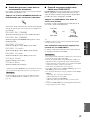
• y indicates a tip for your operation.
• Some operations can be performed by using either the buttons on the main unit or on the remote control. In cases when the button
names differ between the main unit and the remote control, the button name on the remote control is given in parentheses.
• This manual is printed prior to production. Design and specifications are subject to change in part as a result of improvements, etc. In
case of differences between the manual and product, the product has priority.
Manufactured under license from Dolby Laboratories.
“Dolby”, “Pro Logic”, “Surround EX”, and the double-D symbol
are trademarks of Dolby Laboratories.
“SILENT CINEMA” is a trademark of YAMAHA
CORPORATION.
“DTS”, “DTS-ES”, “Neo:6” and “DTS 96/24” are trademarks of
Digital Theater Systems, Inc.
THX and the THX logo are registered trademarks of THX Ltd.
Surround EX is a jointly developed technology of THX and
Dolby Laboratories, Inc. and is a trademark of Dolby
Laboratories, Inc. All rights reserved. Used under authorization.
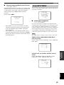
We Want You Listening For A Lifetime
YAMAHA and the Electronic Industries Association’s Consumer Electronics Group want you to get the most out of your
equipment by playing it at a safe level. One that lets the sound come through loud and clear without annoying blaring or
distortion – and, most importantly, without affecting your sensitive hearing. Since hearing damage from loud sounds is
often undetectable until it is too late, YAMAHA and the Electronic Industries Association’s Consumer Electronics Group
recommend you to avoid prolonged exposure from excessive volume levels.
FEATURES

GETTING STARTED
3
INTRODUCTION
English
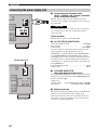
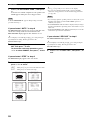
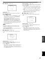
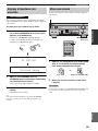
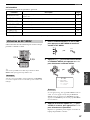
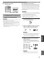
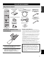
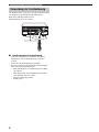
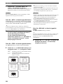
Please check that you received all of the following parts.
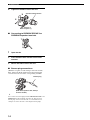
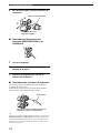
1 Press the part and slide the battery
compartment cover off.
2 Insert the four supplied batteries (AAA, R03,
UM-4) according to the polarity markings on
the inside of the battery compartment.
3 Slide the cover back until it snaps into place.
Notes on batteries
• Change all of the batteries if you notice conditions such as the
operation range of the remote control decreases, the indicator
does not flash, or its light or display window become dim.
• Do not use old batteries together with new ones.
• Do not use different types of batteries (such as alkaline and
manganese batteries) together. Read the packaging carefully as
these different types of batteries may have the same shape and
color.
• If the batteries have leaked, dispose of them immediately. Avoid
touching the leaked material or letting it come into contact with
clothing, etc. Clean the battery compartment thoroughly before
installing new batteries.
• Do not throw away batteries with general house waste; dispose
of them correctly in accordance with your local regulations.
GETTING STARTED
Supplied accessories
CLEAR
LEARN
RE–NAME
SET MENU
MENU
FREQ/RDS EON MODE PTY SEEK START
REC
DISC SKIP
EFFECT
TEST
RETURN
ON SCREEN
DISPLAY
STRAIGHT
NIGHT
AUDIO
PURE DIRECT
ENTER
LEVEL
TITLE
A/B/C/D/E
SELECT
DTV DVR/VCR2VCR 1 DVD
V
-
AUX
CBL/SAT MD/TAPE
CD-R
PHONO TUNER CD
MULTI CH IN
THX STANDARD EXTD. SUR
ENTERTAIN
MUSIC TV THTR MOVIE
STEREO HALL JAZZ
ROCK
VOL
+
–
3421
90
+10
ENT.
5678
POWER POWER POWER
SYSTEM
STANDBY
AVTV
SLEEP
INPUT MODE
A
B
CH
+
–
TV VOL
TV MUTE TV INPUT
MUTE
+
–
AMP
SOURCE
TV
MACROONOFF
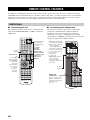
Remote control
Batteries (4)
(AAA, R03, UM-4)
Indoor FM antenna
(U.S.A., Canada, China,
Korea, Asia and General
models)
AM loop antenna
Optimizer microphone
75-ohm/300-ohm
antenna adapter
(U.K. model only)
Speaker terminal wrench
Power Cord
(U.S.A., Canada, U.K., Europe, Australia,
China and Korea models)
Indoor FM antenna
(U.K., Europe and
Australia models)
Installing batteries in the remote
control
1
3
2
If the remote control is without batteries for more than
2 minutes, or if exhausted batteries remain in the
remote control, the contents of the memory may be
cleared. When the memory is cleared, insert new
batteries, set up the remote control code and program
any acquired functions that may have been cleared.

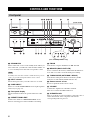
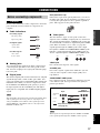
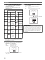
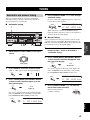
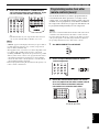
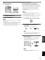
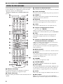
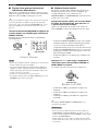
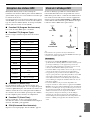
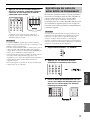
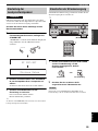
CONTROLS AND FUNCTIONS
4
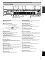
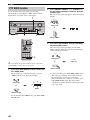
1 STANDBY/ON
Turns on this unit or sets it to the standby mode. When you
turn on this unit, you will hear a click and there will be a 6
to 7-second delay before this unit can reproduce sound.
In standby mode, this unit consumes a small amount of power in
order to receive infrared-signals from the remote control.
2 INPUT selector
Selects the input source you want to listen to or watch.
3 PURE DIRECT
Turns on or off the PURE DIRECT mode. Lights up when
turned on (see page 37).
4 Front panel display
Shows information about the operational status of this
unit.
5 PRESET/TUNING EDIT
Switches the function of PRESET/TUNING l / h
between selecting preset station numbers and tuning.
6 FM/AM
Switches the reception band between FM and AM.
7 MEMORY (MAN’L/AUTO FM)
Stores a station in the memory. Hold down this button for
more than 3 seconds to start automatic preset tuning.
8 TUNING MODE (AUTO/MAN’L MONO)
Switches the tuning mode between automatic (AUTO
indicator on) and manual (AUTO indicator off).
9 Remote control sensor
Receives signals from the remote control.
0 VOLUME
Controls the output level of all audio channels.
This does not affect the REC OUT level.
A SPEAKERS A/B
Turn on or off the set of front speakers connected to the A
and/or B terminals on the rear panel each time the
corresponding button is pressed.
CONTROLS AND FUNCTIONS
Front panel
A
SPEAKERS
MULTI CH
B
INPUT MODE
PURE DIRECT
INPUT
A/B/C/D/E
FM/AM
EDIT
SILENT CINEMA S VIDEO VIDEO L
VIDEO AUX
AUDIO R OPTICAL
MEMORY
PHONES
MAN'L/AUTO FM AUTO/MAN'L MONO
PRESET/
TUNING
PRESET/
TUNING
TUNING
MODE
OPTIMIZER
MIC
TONE CONTROL STRAIGHT
EFFECT
VOLUME
PROGRAM
INPUT
STANDBY
/ON
TUNER
YPAO
1 24 0
ABC DEFGH K
JI
MNOL
3
EON PTY SEEK
MODE START
RDS MODE
/FREQ
67 85
9
(U.S.A. model)
(U.K. and Europe models only)
Note

CONTROLS AND FUNCTIONS
5
English
INTRODUCTION
English
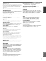
B MULTI CH INPUT
Selects the source connected to the MULTI CH INPUT
jacks. When selected, the MULTI CH INPUT source takes
priority over the source selected with INPUT (or the input
selector buttons on the remote control).
C INPUT MODE
Sets the priority (AUTO, DTS, ANALOG) for the type of
signals received when one component is connected to two
or more of this unit’s input jacks (see page 40).
D OPTIMIZER MIC jack
Use to connect and input audio signals from the supplied
microphone for use with the AUTO SETUP function (see
page 26).
E A/B/C/D/E
Selects one of the 5 preset station groups (A to E).
F PRESET/TUNING l / h
Selects preset station number 1 through 8 when a colon (:)
is displayed next to the band indication in the front panel
display.
Selects the tuning frequency when the colon (:) is not
displayed.
G PHONES (SILENT CINEMA) jack
Outputs audio signals for listening with headphones.
When you connect headphones, no signals are output to
the PRE OUT jacks or to the speakers.
All Dolby Digital and DTS audio signals are mixed down
to the left and right headphone channels.
H VIDEO AUX jacks
Input audio and video signals from an external source such
as a game console. To reproduce source signals from these
jacks, select V-AUX as the input source.
I TONE CONTROL
Use to adjust the bass/treble balance for the front left/right
and center channels (see page 35).
J PROGRAM
Use to select sound field programs or adjust bass/treble
balance (in conjunction with TONE CONTROL).
K STRAIGHT/EFFECT
Switches the sound fields off or on. When STRAIGHT is
selected, input signals (2-channel or multi-channel) are
output directly from their respective speakers without
effect processing.
■ U.K. and Europe models only
L RDS MODE/FREQ
Press this button when the unit is receiving an RDS station
to cycle the display mode between the PS mode, PTY
mode, RT mode, CT mode (if the station offers those RDS
data services) and/or the frequency display mode (see
page 45).
M EON
Press this button to select a radio program type (NEWS,
INFO, AFFAIRS, SPORT) to tune in automatically (see
page 47).
N PTY SEEK MODE
Press this button to set the unit to the PTY SEEK mode
(see page 46).
O PTY SEEK START
Press this button to begin searching for a station after the
desired program type has been selected in the PTY SEEK
mode (see page 46).
■ Opening and closing the front panel
door
When you want to use the controls behind the front panel
door, open the door by gently pressing on the lower part of
the panel. Keep the door closed when not using these
controls.
To open, press gently on the lower part of the panel.

CONTROLS AND FUNCTIONS
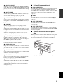
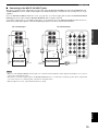
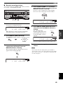
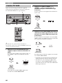
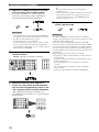
6
This section describes the function of each control on the
remote control used to control this unit. To operate other
components, see “REMOTE CONTROL FEATURES” on
page 68.
1 Infrared window
Outputs infrared control signals. Aim this window at the
component you want to operate.
2 Transmission indicator
Flashes while the remote control is sending signals.
3 Input selector buttons
Select the input source and change the control area.
4 Display window
Shows the name of the selected source component that
you can control.
5 PRESET +/–
Selects preset station numbers when this unit is in tuner
mode.
6 A/B/C/D/E
Selects preset groups when this unit is in tuner mode.
7 LEVEL
Selects the speaker channel to be adjusted and sets the
level.
8 Cursor buttons k / n / l / h / ENTER
Use to select and adjust DSP program parameters or SET
MENU items.
9 TEST
Outputs the test tone to adjust the speaker levels.
0 Sound field program/Numeric buttons
Use to select sound field programs or input numbers.
Use numbers 1 through 8 to select preset stations when
this unit is in tuner mode.
A MACRO ON/OFF
Turns the macro function on and off.
B MACRO
Use to program a series of operations for control by a
single button (see page 74).
C STANDBY
Sets this unit in the standby mode.
D SYSTEM POWER
Turns on the power of this unit.
E INPUT MODE
Sets the priority (AUTO, DTS, ANALOG) for the type of
signals received when one component is connected to two
or more of this unit’s input jacks (see page 40).
F SLEEP
Sets the sleep timer.
G MULTI CH IN
Selects MULTI CH INPUT when using an external
decoder (etc.).
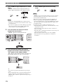
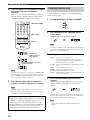
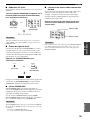
Remote control
CLEAR
LEARN
RE–NAME
SET MENU
MENU
FREQ/RDS EON MODE PTY SEEK START
REC
DISC SKIP
EFFECT
TEST
RETURN
ON SCREEN
DISPLAY
STRAIGHT
NIGHT
AUDIO
PURE DIRECT
ENTER
LEVEL
TITLE
A/B/C/D/E
PRESET
SELECT
DTV DVR/VCR2VCR 1 DVD
V
-
AUX
CBL/SAT MD/TAPE
CD-R
PHONO TUNER CD
MULTI CH IN
THX STANDARD EXTD. SUR
ENTERTAIN
MUSIC TV THTR
MOVIE
STEREO HALL JAZZ
ROCK
VOL
+
–
3421
90
+10
ENT.
5678
POWER POWER POWER
SYSTEM
STANDBY
AVTV
SLEEP
INPUT MODE
A
B
CH
+
–
TV VOL
TV MUTE TV INPUT
MUTE
+
–
AMP
SOURCE
TV
MACROONOFF
C
D
E
G
K
L
M
N
O
P
J
H
Q
R
S
t
F
8
9
7
0
2
1
4
I
6
5
3
U
A
B

CONTROLS AND FUNCTIONS
7
English
INTRODUCTION
English
H SELECT k/n
Selects another component that you can control
independently of the input component selected with the
input selector buttons.
I VOL +/–
Increases or decreases the volume level.
J AMP/SOURCE/TV
Selects the component you want to control with the
remote control.
AMP: Set to this position to operate this unit.
SOURCE: Set to this position to operate the component
selected with an input selector button.
TV: Set to this position to operate the television.
To set the remote control codes for components, see
page 69.
K MUTE
Mutes the sound. Press again to restore the audio output to
the previous volume level.
L PURE DIRECT
Turns on or off PURE DIRECT mode (see page 37).
M SET MENU
Selects the SET MENU mode.
N NIGHT
Turns on or off the night listening modes (see page 38).
O ON SCREEN
Selects the display mode of the on-screen display (OSD)
this unit sends to your monitor.
P STRAIGHT/EFFECT
Switches the sound fields off or on. When STRAIGHT is
selected, input signals (2-channel or multi-channel) are
output directly from their respective speakers without
effect processing.
Q EXTD. SUR
Switches between 5.1 or 6.1/7.1 channel playback of
multi-channel software.
R RE-NAME
Used to change the input source name in the display
window (see page 73).
S CLEAR
Used to clear functions acquired when using the learn and
rename features, or setting remote control codes (see
page 76).
T LEARN
Used to set up the remote control code or program
functions from other remote controls (see pages 69 and
71).
■ U.K. and Europe models only
U RDS tuning buttons
(Available when this unit is in tuner mode)
FREQ/RDS
Press this button when the unit is receiving an RDS station
to cycle the display between the PS mode, PTY mode, RT
mode, CT mode (if the station offers those RDS data
services) and/or the frequency display mode (see page 45).
EON
Press this button to select a radio program type (NEWS,
INFO, AFFAIRS, SPORT) to tune in automatically (see
page 47).
PTY SEEK MODE
Press this button to set the unit to the PTY SEEK mode
(see page 46).
PTY SEEK START
Press this button to begin searching for a station after the
desired program type has been selected in the PTY SEEK
mode (see page 46).

CONTROLS AND FUNCTIONS
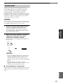
8
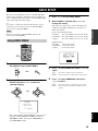
The remote control transmits a directional infrared beam.
Be sure to aim the remote control directly at the remote
control sensor on the main unit during operation.
■ Handling the remote control
• Do not spill water or other liquids on the remote
control.
• Do not drop the remote control.
• Do not leave or store the remote control in the
following types of conditions:
– high humidity such as near a bath
– high temperature such as near a heater or stove
– extremely low temperature
– dusty places
Using the remote control
A
SPEAKERS
MULTI CH
B
INPUT MODE
INPUT
A/B/C/D/E
FM/AM
EDIT
PHONES S VIDEO VIDEO L
VIDEO AUX
AUDIO R OPTICAL
MEMORY
SILENT
MAN'L/AUTO FM AUTO/MAN'L MONO
PRESET/
TUNING
PRESET
/TUNING
TUNING
MODE
MIC
TONE CONTROL STRAIGHT
EFFECT
VOLUME
PROGRAM
INPUT
STANDBY
/ON
TUNER
PURE DIRECT
YPAO
30 30
Approximately 6 m (20 ft)

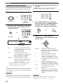
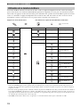
CONTROLS AND FUNCTIONS
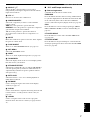
9
English
INTRODUCTION
English
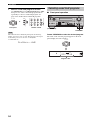
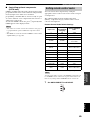
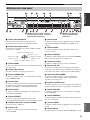
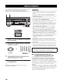
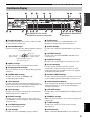
1 Decoder indicators
When any of this unit’s decoders function, the respective
indicator lights up.
2 Sound field indicators
Light to indicate the active DSP sound fields.
3 NIGHT indicator
Lights up when you select night listening mode.
4 Input source indicators
A cursor lights to show the current input source.
5 CINEMA DSP indicator
Lights up when you select a CINEMA DSP sound field
program.
6 YPAO indicator
Lights up during the auto setup procedure and when the
auto setup speaker settings are used without any
modifications.
7 AUTO indicator
Lights up when this unit is in the automatic tuning mode.
8 STEREO indicator
Lights up when this unit is receiving a stereo signal for an
FM stereo broadcast while the AUTO indicator is lit.
9 VOLUME level indicator
Indicates the volume level.
0 THX indicator
Lights up when a THX program is selected.
A PCM indicator
Lights up when this unit is reproducing PCM (pulse code
modulation) digital audio signals.
B SLEEP indicator
Lights up while the sleep timer is on.
C VIRTUAL indicator
Lights up when Virtual CINEMA DSP is active (see
page 39).
D Headphones indicator
Lights up when headphones are connected.
E SP A B indicators
Light up according to the set of front speakers selected.
Both indicators light up when both sets of speakers are
selected, or when bi-wiring.
F SILENT CINEMA indicator
Lights up when headphones are connected and a sound
field program is selected (see page 35).
G Multi-information display
Shows the current sound field program name and other
information when adjusting or changing settings.
H HiFi DSP indicator
Lights up when you select a HiFi DSP sound field
program.
I MEMORY indicator
Blinks to show a station can be stored.
J TUNED indicator
Lights up when this unit is tuned into a station.
K MUTE indicator
Blinks while the MUTE function is on.
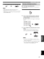
Front panel display
V–AUX
DVR/VCR2
VCR 1
CBL/SAT
DTV DVD
MD/TAPE
CD–R CD TUNER
PHONO
96
24
NIGHT
VIRTUAL
ZONE2
ZONE3
ZONE4
SLEEP
YPAO
HiFi DSP
STEREO
TUNED
EON
AUTO
MEMORY
MUTE
VOLUME
DIGITAL
PL
MATRIX
DISCRETE
PCM
THX
PL
EX
SILENT
CINEMA
A B
SP
LFE
ft
mS
dB
96/24
LL C R
SL SB SR
PL x
PS PTY RT CT
PTY
HOLD
dB
AFGHK
135678
BE
2
C
9
DIJ
PQ
LM
4
NO0
(U.S.A., Canada, U.K., Europe and
Australia models only)
(U.K. and Europe models only)
Presence DSP sound field
Listening position
Left surround
DSP sound field
Right surround
DSP sound field
Surround back DSP sound field

CONTROLS AND FUNCTIONS
10
L 96/24 indicator
Lights up when a DTS 96/24 signal is input to this unit.
M LFE indicator
Lights up when the input signal contains an LFE signal.
N Input channel indicators
Indicate the channel components of current digital input
signal.
O Presence and surround back speaker
indicators
Indicate the connection of presence and/or surround back
speakers when using the SPEAKERS setting (page 32) or
SP LEVEL setting (page 60).
P ZONE 2/ZONE 3 indicators
(U.S.A., Canada, U.K., Europe and Australia
models only)
Light up when Zone 2 or Zone 3 power is on.
Q RDS indicators
(U.K. and Europe models only)
The name(s) of the RDS data offered by the currently
received RDS station light(s) up.
EON lights up when an RDS station that offers the EON
data service is being received.
PTY HOLD lights up while searching for stations in the
PTY SEEK mode.

CONTROLS AND FUNCTIONS
11
English
INTRODUCTION
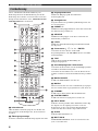
English
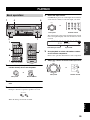
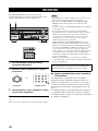
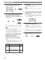
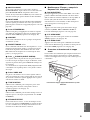
1 DIGITAL OUTPUT jacks
See page 21 for details.
2 Audio component jacks
See page 21 for connection information.
3 Video component jacks
See pages 18 and 20 for connection information.
4 RS-232C terminal
(U.S.A., Canada, U.K., Europe and Australia
models only)
This is a control expansion terminal for commercial use.
Consult your dealer for details.
5 REMOTE IN/OUT jacks
(U.S.A., Canada, U.K., Europe and Australia
models only)
See page 80 for connection information.
6 CONTROL OUT jack
(U.S.A., Canada, U.K., Europe and Australia
models only)
See page 80 for connection information.
7 AC OUTLET(S)
Use to supply power to your other A/V components (see
page 24).
8 AC INLET (U.S.A., Canada, U.K., Europe,
Australia, China and Korea models only)
Use this inlet to plug in the supplied power cable (see
page 24).
9 DIGITAL INPUT jacks
See pages 18, 20 and 21 for details.
0 MULTI CH INPUT jacks
See page 19 for connection information.
A ZONE 2/ZONE 3 OUTPUT jacks
(U.S.A., Canada, U.K., Europe and Australia
models only)
See page 80 for connection information.
B Antenna terminals
See page 23 for connection information.
C PRE OUT jacks
See page 22 for connection information.
D Speaker terminals
See page 13 for connection information.
E PRESENCE/ZONE 2 speaker terminals
(U.S.A., Canada, U.K., Europe and Australia
models)
PRESENCE speaker terminals
(other models)
See page 14 for connection information.
< Asia and General models only >
FREQUENCY STEP switch
See page 23.
VOLTAGE SELECTOR
See page 24.
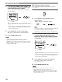
Rear panel
AC OUTLETS
AC OUTLETS
GND
SPEAKERS
FRONT
SURROUND
FRONT
CENTER
PRE OUT
SUB
WOOFER
SURROUND BACK
/PRESENCE
SURROUND
SURROUND BACK
CENTER
R
R
R
L
R
L
R
L
L
R
R
L
L
L
CENTER
SUB
WOOFER
MONITOR OUT
MULTI CH INPUT OUTPUT
AUDIO AUDIO VIDEO
S VIDEO
DVD
DTV
CBL
/SAT
VIDEO
R
L
R
L
IN
(
PLAY
)
IN
(
PLAY
)
OUT
(
REC
)
OUT
(
REC
)
CD-R
MD/TAPE
CD
PHONO
IN
OUT
OUT
ZONE 2
ZONE 3
DVR/
VCR 2
VCR 1
CD-R
IN
FRONT (6CH)/SB (8CH)
SURROUND
TUNER
AM
ANT
GND
FM ANT
75Ω
UNBAL.
COMPONENT VIDEO
P
R
DVD
MONITOR OUT
DTV
P
B
Y
DIGITAL OUTPUT
DIGITAL INPUT
OPTICAL
MD
/
TAP E
CD-R
DVD
DTV
CBL/SAT
CD
CD
DVD
DVR/
VCR 2
COAXIAL
+
–
+
–
+
–
+
+
––
–
+
+
+
+
+
–
–
–
–
A
B
PRESENCE/ZONE 2
CONTROL OUTREMOTE
IN OUT
+12V 15mA MAX.
SINGLE
RS-232C
AC OUTLETS
12 3 54678
EDCBA09
(U.S.A. model)

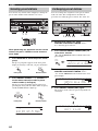
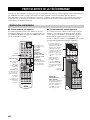
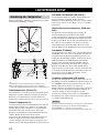
SPEAKER SETUP
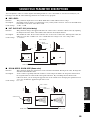
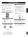
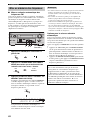
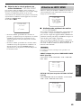
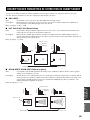
12
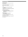
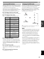
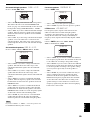
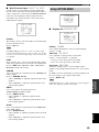
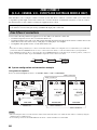
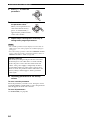
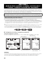
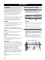
For best results, place the speakers as illustrated below.
.
y
The illustrations show the standard speaker setting recommended
by the ITU-R (see page 96). You can use it to enjoy CINEMA
DSP, multi-channel audio sources, and THX.
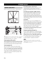
Front speakers (FR and FL)
The front speakers are used for the main source sound plus
effect sounds. Place these speakers an equal distance from
the ideal listening position. The distance of each speaker
from each side of the video monitor should be the same.
Center speaker (C)
The center speaker is for the center channel sounds
(dialog, vocals, etc.). If for some reason it is not practical
to use a center speaker, you can do without it. Best results,
however, are obtained with the full system. Align the front
face of the center speaker with the front face of your video
monitor. Place the speaker centrally between the front
speakers and as close to the monitor as possible, such as
directly over or under it.
Surround speakers (SR and SL)
The surround speakers are used for effect and surround
sounds. Place these speakers behind your listening
position, facing slightly inwards, about 1.8 m (6 ft) above
the floor.
Surround back speakers (SBR and SBL)
The surround back speakers supplement the surround
speakers and provide for more realistic front-to-back
transitions. Place these speakers directly behind the
listening position and at the same height as the surround
speakers. They should be positioned at least 30 cm (12 in)
apart. Ideally, they should be positioned at the same width
as the front speakers.
Subwoofer
The use of a subwoofer, such as the YAMAHA Active
Servo Processing Subwoofer System, is effective not only
for reinforcing bass frequencies from any or all channels,
but also for high fidelity reproduction of the LFE (low-
frequency effect) channel included in Dolby Digital and
DTS software. The position of the subwoofer is not so
critical, because low bass sounds are not highly
directional. But it is better to place the subwoofer near the
front speakers. Turn it slightly toward the center of the
room to reduce wall reflections.
Presence speakers (PR and PL)
Presence speakers supplement the sound from the front
speakers with extra ambient effects produced by CINEMA
DSP (see page 49). These effects include sounds that
filmmakers intend to locate a little farther back behind the
screen in order to create more theater-like ambience. Place
these speakers at the front of the room about 0.5 - 1 m
(1 - 3 ft) outside the front speakers, facing slightly
inwards, and about 1.8 m (6 ft) above the floor.
Surround back and presence speakers do not output sound
simultaneously. You can set to prioritize either set of speakers in
SOUND MENU (see page 63).
SPEAKER SETUP
Speaker placement
More than 30 cm (12 in)
60˚
30˚
PL
PR
SBR
SBL
FL
FR
C
SL
SR
SR
80˚
SL
1.8 m (6 ft)
1.8 m (6 ft)
Note

13
SPEAKER SETUP
PREPARATION
English
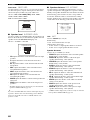
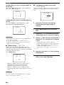
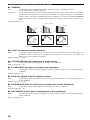
■ Di-pole speaker layout
Either di-pole or direct radiating speaker types can be used
for THX surround. If you choose di-pole speakers, please
place the surround and surround back speakers according
to the speaker layout below.
Be sure to connect the left channel (L), right channel (R),
“+” (red) and “–” (black) properly. If the connections are
faulty, no sound will be heard from the speakers, and if the
polarity of the speaker connections is incorrect, the sound
will be unnatural and lack bass.
• If you will use 6 ohm speakers, be sure to set
this unit’s speaker impedance setting to 6
ohms before using (see page 25).
• Before connecting the speakers, make sure that the
power of this unit is off.
• Do not let the bare speaker wires touch each other or do
not let them touch any metal part of this unit. This
could damage this unit and/or speakers.
• Use magnetically shielded speakers. If this type of
speaker still creates interference with the monitor,
place the speakers away from the monitor.
A speaker cord is actually a pair of insulated cables
running side by side. One cable is colored or shaped
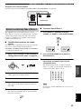
differently, perhaps with a stripe, groove or ridges.
Connect the striped (grooved, etc.) cable to the “+” (red)
terminals on this unit and your speaker. Connect the plain
cable to the “–” (black) terminals.
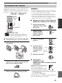
1 Remove approximately 10 mm (3/8 in) of
insulation from each of the speaker cables.
2 Twist the exposed wires of the cable together
to prevent short circuits.
3 Loosen the knob.
The supplied speaker terminal wrench is useful for
loosening or tightening knobs.
4 Insert one bare wire into the hole in the side
of each terminal.
FL
SR
SL
FR
C
SBR
SBL
30˚ 30˚
: Di-pole speaker
: Direction of di-pole speaker
Speaker connections
CAUTION
10 mm (3/8 in)
1
2

14
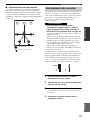
SPEAKER SETUP
5 Tighten the knob to secure the wire.
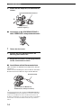
■ Connecting to PRESENCE/ZONE 2 or
PRESENCE speaker terminals
1 Open the tab.
2 Insert one bare wire into the hole of each
terminal.
3 Return the tab to secure the wire.
■ Banana plug connections
(With the exception of U.K., Europe and Asia models)
First, tighten the knob and then insert the banana plug
connector into the end of the corresponding terminal.
y
You can also use banana plugs with the PRESENCE/ZONE 2 and
PRESENCE speaker terminals. Open the tab, then insert one
banana plug connector into the hole of each terminal. Do not
attempt to close the tabs after connecting the banana plugs.
Red: positive (+)
Black: negative (–)
5
4
3
Speaker terminal wrench
2
1
3
Banana plug
(With the exception of U.K., Europe
and Asia models)

15
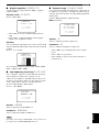
SPEAKER SETUP
PREPARATION
English
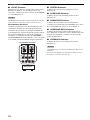
RC-232C
SPEAKERS
FRONT
CENTER
PRE OUT
SUB
WOOFER
SURROUND
SURROUND BACK
R
R
L
R
R
L
L
L
+
–
+
–
+
–
+
+
––
–
+
+
+
+
+
–
–
–
–
PRESENCE/ZONE 2
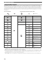
SINGLE
231
7 8 6
5
10
9
4
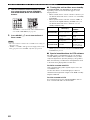
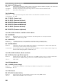
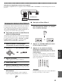
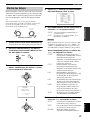
Subwoofer with
built-in amplifier
Center
speaker
Front speakers (A)
Surround back speakers
LeftRight
Left
Right LeftRight
Surround speakers
Front
speakers
(B)
1
2
3
4
5
6
9
10
8
7
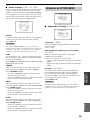
Speaker layout
(U.S.A. model)
LeftRight
Presence speakers
• You can connect both surround back and presence speakers to this unit, but they do not output sound simultaneously.You can set
to prioritize either set of speakers in SOUND MENU (see page 63).
• The surround back speakers output the surround back channel included in Dolby Digital EX and DTS-ES software and only
operate when the Dolby Digital EX, DTS-ES or Dolby Pro Logic IIx decoder is turned on.
• The presence speakers output ambient effects created by the DSP sound fields. They do not output sound when other sound fields
are selected.

16
SPEAKER SETUP
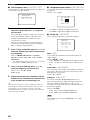
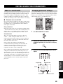
■ FRONT terminals
Connect one or two speaker systems to these terminals. If
you use only one speaker system, connect it to either the
FRONT A or B terminals.
The Canada model cannot output to two separate speaker systems
simultaneously.
Bi-wired connection
The unit also allows you to make bi-wired connections to
one speaker system. Use two pairs of speaker cables for
each speaker (one pair for the woofer and one pair for the
tweeter/mid-range). To use the bi-wired connections, press
SPEAKERS A and SPEAKERS B on the front panel so
that both SP A and B light up in the front panel display.
■ CENTER terminals
Connect a center speaker to these terminals.
■ SURROUND terminals
Connect surround speakers to these terminals.
■ SUBWOOFER jack
Connect a subwoofer with a built-in amplifier, such as the
YAMAHA Active Servo Processing Subwoofer System,
to this jack.
■ SURROUND BACK terminals
Connect surround back speakers to these terminals. If you
only connect one surround back speaker, connect it to the
left (L) terminals.
■ PRESENCE terminals
Connect presence speakers to these terminals.
(U.S.A., Canada, U.K., Europe and Australia models only)
You can also use these terminals to connect Zone 2 speakers (see
page 67).
Note
Bi-wired connection
FRONT
R
L
+
–
+
–
+
+
–
–
A
B
This unit
Note

CONNECTIONS
17
PREPARATION
English
Do not connect this unit or other components to the mains
power until all connections between components are
complete.
■ Cable indications
■ Analog jacks
You can input analog signals from audio components by
connecting audio pin cables to the analog jacks on this
unit. Connect red plugs to the right jacks and white plugs
to the left jacks.
■ Digital jacks
This unit has digital jacks for direct transmission of digital
signals through either coaxial or fiber optic cables. You
can use the digital jacks to input PCM, Dolby Digital and
DTS bitstreams. When you connect components to both
the COAXIAL and OPTICAL jacks, priority is given to
the input signals from the COAXIAL jack. All digital
input jacks are compatible with 96-kHz sampling digital
signals.
This unit handles digital and analog signals independently. Thus
audio signals input to the analog jacks are only output to the
analog OUT (REC) jacks. Likewise audio signals input to the
digital (OPTICAL or COAXIAL) jacks are only output to the
DIGITAL OUTPUT jacks.
Dust protection cap
Pull out the cap from the optical jack before you connect
the fiber optic cable. Do not discard the cap. When you are
not using the optical jack, be sure to put the cap back in
place. This cap protects the jack from dust.
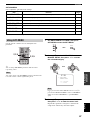
■ Video jacks
This unit has three types of video jacks. Connection
depends on the availability of input jacks on your monitor.
The signals input through the S VIDEO jacks on this unit
are automatically converted for output through the VIDEO
jacks. When V CONV. is set to “ON” (see page 66),
signals input through the VIDEO jacks can be output
through the S VIDEO and COMPONENT VIDEO jacks.
Likewise, signals input through the S VIDEO jacks can
also be output through the COMPONENT VIDEO jacks.
VIDEO jack
For conventional composite video signals.
S VIDEO jack
For S-video signals, separated into luminance (Y) and
color (C) video signals to achieve high-quality color
reproduction.
COMPONENT VIDEO jacks
For component signals, separated into luminance (Y) and
color difference (P
B, PR) to provide the best quality in
picture reproduction.
When signals are input through both the S VIDEO and VIDEO
jacks, signals input through the S VIDEO jack have priority.
CONNECTIONS
Before connecting components
Note
CAUTION
S
V
O
V
V
V
L
R
C
left analog cables
right analog cables
optical cables
coaxial cables
video cables
S-video cables
For analog signals
For digital signals
For video signals
Note
VIDEO
S VIDEO
COMPONENT VIDEO
P
R
P
B
Y
S VIDEO
VIDEO
COMPONENT
VIDEO
Signal flow inside this unit
Only when V CONV. is set to ON
(see page 66)
Output
(MONITOR OUT)
Input

18
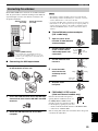
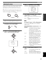
CONNECTIONS
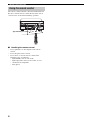
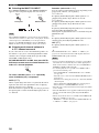
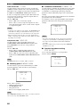
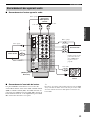
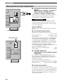
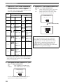
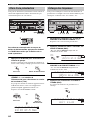
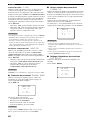
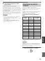
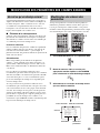
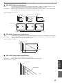
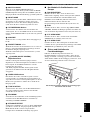
■ Connections for DVD playback
Connecting video components
GND
M
SUR
SUB
WOO
CENTER
SUB
WOOFER
MONITOR OUT
MULCH CH INPUT OUTPUT
AUDIO AUDIO VIDEO
S VIDEO
DVD
VIDEO
R
L
R
L
IN
(
PLAY
)
IN
(
PLAY
)
OUT
(
REC
)
OUT
(
REC
)
CD-R
MD/TAPE
CD
PHONO
ZONE 2
ZONE 3
MAIN/SURROUND BACK
SURROUND
TUNER
75Ω
UNBAL.
AM
ANT
GND
FM ANT
COMPONENT VIDEO
P
R
DVD
MONITOR OUT
P
B
Y
DIGITAL OUTPUT
DIGITAL INPUT
OPTICAL
MD
/
TAPE
CD-R
DVD
CBL/SAT
CD
CD
DVD
DTV
COAXIAL
LR
C
O
DVD player
Video
monitor
(U.S.A. model)
Optical out Video out
Audio out
Video in
Coaxial out
Sayfa yükleniyor ...
Sayfa yükleniyor ...
Sayfa yükleniyor ...
Sayfa yükleniyor ...
Sayfa yükleniyor ...
Sayfa yükleniyor ...
Sayfa yükleniyor ...
Sayfa yükleniyor ...
Sayfa yükleniyor ...
Sayfa yükleniyor ...
Sayfa yükleniyor ...
Sayfa yükleniyor ...
Sayfa yükleniyor ...
Sayfa yükleniyor ...
Sayfa yükleniyor ...
Sayfa yükleniyor ...
Sayfa yükleniyor ...
Sayfa yükleniyor ...
Sayfa yükleniyor ...
Sayfa yükleniyor ...
Sayfa yükleniyor ...
Sayfa yükleniyor ...
Sayfa yükleniyor ...
Sayfa yükleniyor ...
Sayfa yükleniyor ...
Sayfa yükleniyor ...
Sayfa yükleniyor ...
Sayfa yükleniyor ...
Sayfa yükleniyor ...
Sayfa yükleniyor ...
Sayfa yükleniyor ...
Sayfa yükleniyor ...
Sayfa yükleniyor ...
Sayfa yükleniyor ...
Sayfa yükleniyor ...
Sayfa yükleniyor ...
Sayfa yükleniyor ...
Sayfa yükleniyor ...
Sayfa yükleniyor ...
Sayfa yükleniyor ...
Sayfa yükleniyor ...
Sayfa yükleniyor ...
Sayfa yükleniyor ...
Sayfa yükleniyor ...
Sayfa yükleniyor ...
Sayfa yükleniyor ...
Sayfa yükleniyor ...
Sayfa yükleniyor ...
Sayfa yükleniyor ...
Sayfa yükleniyor ...
Sayfa yükleniyor ...
Sayfa yükleniyor ...
Sayfa yükleniyor ...
Sayfa yükleniyor ...
Sayfa yükleniyor ...
Sayfa yükleniyor ...
Sayfa yükleniyor ...
Sayfa yükleniyor ...
Sayfa yükleniyor ...
Sayfa yükleniyor ...
Sayfa yükleniyor ...
Sayfa yükleniyor ...
Sayfa yükleniyor ...
Sayfa yükleniyor ...
Sayfa yükleniyor ...
Sayfa yükleniyor ...
Sayfa yükleniyor ...
Sayfa yükleniyor ...
Sayfa yükleniyor ...
Sayfa yükleniyor ...
Sayfa yükleniyor ...
Sayfa yükleniyor ...
Sayfa yükleniyor ...
Sayfa yükleniyor ...
Sayfa yükleniyor ...
Sayfa yükleniyor ...
Sayfa yükleniyor ...
Sayfa yükleniyor ...
Sayfa yükleniyor ...
Sayfa yükleniyor ...
Sayfa yükleniyor ...
Sayfa yükleniyor ...
Sayfa yükleniyor ...
Sayfa yükleniyor ...
Sayfa yükleniyor ...
Sayfa yükleniyor ...
Sayfa yükleniyor ...
Sayfa yükleniyor ...
Sayfa yükleniyor ...
Sayfa yükleniyor ...
Sayfa yükleniyor ...
Sayfa yükleniyor ...
Sayfa yükleniyor ...
Sayfa yükleniyor ...
Sayfa yükleniyor ...
Sayfa yükleniyor ...
Sayfa yükleniyor ...
Sayfa yükleniyor ...
Sayfa yükleniyor ...
Sayfa yükleniyor ...
Sayfa yükleniyor ...
Sayfa yükleniyor ...
Sayfa yükleniyor ...
Sayfa yükleniyor ...
Sayfa yükleniyor ...
Sayfa yükleniyor ...
Sayfa yükleniyor ...
Sayfa yükleniyor ...
Sayfa yükleniyor ...
Sayfa yükleniyor ...
Sayfa yükleniyor ...
Sayfa yükleniyor ...
Sayfa yükleniyor ...
Sayfa yükleniyor ...
Sayfa yükleniyor ...
Sayfa yükleniyor ...
Sayfa yükleniyor ...
Sayfa yükleniyor ...
Sayfa yükleniyor ...
Sayfa yükleniyor ...
Sayfa yükleniyor ...
Sayfa yükleniyor ...
Sayfa yükleniyor ...
Sayfa yükleniyor ...
Sayfa yükleniyor ...
Sayfa yükleniyor ...
Sayfa yükleniyor ...
Sayfa yükleniyor ...
Sayfa yükleniyor ...
Sayfa yükleniyor ...
Sayfa yükleniyor ...
Sayfa yükleniyor ...
Sayfa yükleniyor ...
Sayfa yükleniyor ...
Sayfa yükleniyor ...
Sayfa yükleniyor ...
Sayfa yükleniyor ...
Sayfa yükleniyor ...
Sayfa yükleniyor ...
Sayfa yükleniyor ...
Sayfa yükleniyor ...
Sayfa yükleniyor ...
Sayfa yükleniyor ...
Sayfa yükleniyor ...
Sayfa yükleniyor ...
Sayfa yükleniyor ...
Sayfa yükleniyor ...
Sayfa yükleniyor ...
Sayfa yükleniyor ...
Sayfa yükleniyor ...
Sayfa yükleniyor ...
Sayfa yükleniyor ...
Sayfa yükleniyor ...
Sayfa yükleniyor ...
Sayfa yükleniyor ...
Sayfa yükleniyor ...
Sayfa yükleniyor ...
Sayfa yükleniyor ...
Sayfa yükleniyor ...
Sayfa yükleniyor ...
Sayfa yükleniyor ...
Sayfa yükleniyor ...
Sayfa yükleniyor ...
Sayfa yükleniyor ...
Sayfa yükleniyor ...
Sayfa yükleniyor ...
Sayfa yükleniyor ...
Sayfa yükleniyor ...
Sayfa yükleniyor ...
Sayfa yükleniyor ...
Sayfa yükleniyor ...
Sayfa yükleniyor ...
Sayfa yükleniyor ...
Sayfa yükleniyor ...
Sayfa yükleniyor ...
Sayfa yükleniyor ...
Sayfa yükleniyor ...
Sayfa yükleniyor ...
Sayfa yükleniyor ...
Sayfa yükleniyor ...
Sayfa yükleniyor ...
Sayfa yükleniyor ...
Sayfa yükleniyor ...
Sayfa yükleniyor ...
Sayfa yükleniyor ...
Sayfa yükleniyor ...
Sayfa yükleniyor ...
Sayfa yükleniyor ...
Sayfa yükleniyor ...
Sayfa yükleniyor ...
Sayfa yükleniyor ...
Sayfa yükleniyor ...
Sayfa yükleniyor ...
Sayfa yükleniyor ...
Sayfa yükleniyor ...
Sayfa yükleniyor ...
Sayfa yükleniyor ...
Sayfa yükleniyor ...
Sayfa yükleniyor ...
Sayfa yükleniyor ...
Sayfa yükleniyor ...
Sayfa yükleniyor ...
Sayfa yükleniyor ...
Sayfa yükleniyor ...
Sayfa yükleniyor ...
Sayfa yükleniyor ...
Sayfa yükleniyor ...
Sayfa yükleniyor ...
Sayfa yükleniyor ...
Sayfa yükleniyor ...
Sayfa yükleniyor ...
Sayfa yükleniyor ...
Sayfa yükleniyor ...
Sayfa yükleniyor ...
Sayfa yükleniyor ...
Sayfa yükleniyor ...
Sayfa yükleniyor ...
Sayfa yükleniyor ...
Sayfa yükleniyor ...
Sayfa yükleniyor ...
Sayfa yükleniyor ...
Sayfa yükleniyor ...
Sayfa yükleniyor ...
Sayfa yükleniyor ...
Sayfa yükleniyor ...
Sayfa yükleniyor ...
Sayfa yükleniyor ...
Sayfa yükleniyor ...
Sayfa yükleniyor ...
Sayfa yükleniyor ...
Sayfa yükleniyor ...
Sayfa yükleniyor ...
Sayfa yükleniyor ...
Sayfa yükleniyor ...
Sayfa yükleniyor ...
Sayfa yükleniyor ...
Sayfa yükleniyor ...
Sayfa yükleniyor ...
Sayfa yükleniyor ...
Sayfa yükleniyor ...
Sayfa yükleniyor ...
Sayfa yükleniyor ...
Sayfa yükleniyor ...
Sayfa yükleniyor ...
Sayfa yükleniyor ...
Sayfa yükleniyor ...
Sayfa yükleniyor ...
Sayfa yükleniyor ...
Sayfa yükleniyor ...
Sayfa yükleniyor ...
Sayfa yükleniyor ...
Sayfa yükleniyor ...
Sayfa yükleniyor ...
Sayfa yükleniyor ...
Sayfa yükleniyor ...
Sayfa yükleniyor ...
Sayfa yükleniyor ...
Sayfa yükleniyor ...
Sayfa yükleniyor ...
Sayfa yükleniyor ...
Sayfa yükleniyor ...
Sayfa yükleniyor ...
Sayfa yükleniyor ...
Sayfa yükleniyor ...
Sayfa yükleniyor ...
Sayfa yükleniyor ...
Sayfa yükleniyor ...
Sayfa yükleniyor ...
Sayfa yükleniyor ...
Sayfa yükleniyor ...
Sayfa yükleniyor ...
Sayfa yükleniyor ...
Sayfa yükleniyor ...
Sayfa yükleniyor ...
Sayfa yükleniyor ...
Sayfa yükleniyor ...
Sayfa yükleniyor ...
Sayfa yükleniyor ...
Sayfa yükleniyor ...
Sayfa yükleniyor ...
Sayfa yükleniyor ...
Sayfa yükleniyor ...
Sayfa yükleniyor ...
Sayfa yükleniyor ...
Sayfa yükleniyor ...
Sayfa yükleniyor ...
Sayfa yükleniyor ...
Sayfa yükleniyor ...
Sayfa yükleniyor ...
Sayfa yükleniyor ...
Sayfa yükleniyor ...
Sayfa yükleniyor ...
Sayfa yükleniyor ...
Sayfa yükleniyor ...
Sayfa yükleniyor ...
Sayfa yükleniyor ...
Sayfa yükleniyor ...
Sayfa yükleniyor ...
Sayfa yükleniyor ...
Sayfa yükleniyor ...
Sayfa yükleniyor ...
Sayfa yükleniyor ...
Sayfa yükleniyor ...
Sayfa yükleniyor ...
Sayfa yükleniyor ...
Sayfa yükleniyor ...
Sayfa yükleniyor ...
Sayfa yükleniyor ...
Sayfa yükleniyor ...
Sayfa yükleniyor ...
Sayfa yükleniyor ...
Sayfa yükleniyor ...
Sayfa yükleniyor ...
Sayfa yükleniyor ...
Sayfa yükleniyor ...
Sayfa yükleniyor ...
Sayfa yükleniyor ...
Sayfa yükleniyor ...
Sayfa yükleniyor ...
Sayfa yükleniyor ...
Sayfa yükleniyor ...
Sayfa yükleniyor ...
Sayfa yükleniyor ...
Sayfa yükleniyor ...
Sayfa yükleniyor ...
Sayfa yükleniyor ...
Sayfa yükleniyor ...
Sayfa yükleniyor ...
Sayfa yükleniyor ...
Sayfa yükleniyor ...
Sayfa yükleniyor ...
Sayfa yükleniyor ...
Sayfa yükleniyor ...
Sayfa yükleniyor ...
Sayfa yükleniyor ...
Sayfa yükleniyor ...
Sayfa yükleniyor ...
Sayfa yükleniyor ...
Sayfa yükleniyor ...
Sayfa yükleniyor ...
Sayfa yükleniyor ...
Sayfa yükleniyor ...
Sayfa yükleniyor ...
Sayfa yükleniyor ...
Sayfa yükleniyor ...
Sayfa yükleniyor ...
Sayfa yükleniyor ...
Sayfa yükleniyor ...
Sayfa yükleniyor ...
Sayfa yükleniyor ...
Sayfa yükleniyor ...
Sayfa yükleniyor ...
Sayfa yükleniyor ...
Sayfa yükleniyor ...
Sayfa yükleniyor ...
Sayfa yükleniyor ...
Sayfa yükleniyor ...
Sayfa yükleniyor ...
Sayfa yükleniyor ...
Sayfa yükleniyor ...
Sayfa yükleniyor ...
Sayfa yükleniyor ...
Sayfa yükleniyor ...
Sayfa yükleniyor ...
Sayfa yükleniyor ...
Sayfa yükleniyor ...
Sayfa yükleniyor ...
Sayfa yükleniyor ...
Sayfa yükleniyor ...
Sayfa yükleniyor ...
Sayfa yükleniyor ...
Sayfa yükleniyor ...
Sayfa yükleniyor ...
Sayfa yükleniyor ...
Sayfa yükleniyor ...
Sayfa yükleniyor ...
Sayfa yükleniyor ...
Sayfa yükleniyor ...
Sayfa yükleniyor ...
Sayfa yükleniyor ...
Sayfa yükleniyor ...
Sayfa yükleniyor ...
Sayfa yükleniyor ...
Sayfa yükleniyor ...
Sayfa yükleniyor ...
Sayfa yükleniyor ...
Sayfa yükleniyor ...
Sayfa yükleniyor ...
Sayfa yükleniyor ...
Sayfa yükleniyor ...
Sayfa yükleniyor ...
Sayfa yükleniyor ...
Sayfa yükleniyor ...
Sayfa yükleniyor ...
Sayfa yükleniyor ...
Sayfa yükleniyor ...
Sayfa yükleniyor ...
Sayfa yükleniyor ...
Sayfa yükleniyor ...
Sayfa yükleniyor ...
Sayfa yükleniyor ...
Sayfa yükleniyor ...
Sayfa yükleniyor ...
Sayfa yükleniyor ...
Sayfa yükleniyor ...
Sayfa yükleniyor ...
Sayfa yükleniyor ...
Sayfa yükleniyor ...
Sayfa yükleniyor ...
Sayfa yükleniyor ...
Sayfa yükleniyor ...
Sayfa yükleniyor ...
Sayfa yükleniyor ...
Sayfa yükleniyor ...
Sayfa yükleniyor ...
Sayfa yükleniyor ...
Sayfa yükleniyor ...
Sayfa yükleniyor ...
Sayfa yükleniyor ...
Sayfa yükleniyor ...
Sayfa yükleniyor ...
Sayfa yükleniyor ...
Sayfa yükleniyor ...
Sayfa yükleniyor ...
Sayfa yükleniyor ...
Sayfa yükleniyor ...
Sayfa yükleniyor ...
Sayfa yükleniyor ...
Sayfa yükleniyor ...
Sayfa yükleniyor ...
Sayfa yükleniyor ...
Sayfa yükleniyor ...
Sayfa yükleniyor ...
Sayfa yükleniyor ...
Sayfa yükleniyor ...
Sayfa yükleniyor ...
Sayfa yükleniyor ...
Sayfa yükleniyor ...
Sayfa yükleniyor ...
Sayfa yükleniyor ...
Sayfa yükleniyor ...
Sayfa yükleniyor ...
Sayfa yükleniyor ...
Sayfa yükleniyor ...
Sayfa yükleniyor ...
Sayfa yükleniyor ...
Sayfa yükleniyor ...
Sayfa yükleniyor ...
Sayfa yükleniyor ...
Sayfa yükleniyor ...
Sayfa yükleniyor ...
Sayfa yükleniyor ...
Sayfa yükleniyor ...
Sayfa yükleniyor ...
Sayfa yükleniyor ...
Sayfa yükleniyor ...
Sayfa yükleniyor ...
Sayfa yükleniyor ...
Sayfa yükleniyor ...
Sayfa yükleniyor ...
Sayfa yükleniyor ...
Sayfa yükleniyor ...
Sayfa yükleniyor ...
Sayfa yükleniyor ...
Sayfa yükleniyor ...
Sayfa yükleniyor ...
Sayfa yükleniyor ...
Sayfa yükleniyor ...
Sayfa yükleniyor ...
Sayfa yükleniyor ...
Sayfa yükleniyor ...
Sayfa yükleniyor ...
Sayfa yükleniyor ...
Sayfa yükleniyor ...
Sayfa yükleniyor ...
Sayfa yükleniyor ...
Sayfa yükleniyor ...
Sayfa yükleniyor ...
Sayfa yükleniyor ...
Sayfa yükleniyor ...
Sayfa yükleniyor ...
Sayfa yükleniyor ...
Sayfa yükleniyor ...
Sayfa yükleniyor ...
Sayfa yükleniyor ...
Sayfa yükleniyor ...
Sayfa yükleniyor ...
Sayfa yükleniyor ...
Sayfa yükleniyor ...
Sayfa yükleniyor ...
Sayfa yükleniyor ...
Sayfa yükleniyor ...
Sayfa yükleniyor ...
Sayfa yükleniyor ...
Sayfa yükleniyor ...
Sayfa yükleniyor ...
Sayfa yükleniyor ...
Sayfa yükleniyor ...
Sayfa yükleniyor ...
Sayfa yükleniyor ...
Sayfa yükleniyor ...
Sayfa yükleniyor ...
Sayfa yükleniyor ...
Sayfa yükleniyor ...
Sayfa yükleniyor ...
Sayfa yükleniyor ...
Sayfa yükleniyor ...
Sayfa yükleniyor ...
Sayfa yükleniyor ...
Sayfa yükleniyor ...
Sayfa yükleniyor ...
Sayfa yükleniyor ...
Sayfa yükleniyor ...
Sayfa yükleniyor ...
Sayfa yükleniyor ...
Sayfa yükleniyor ...
Sayfa yükleniyor ...
Sayfa yükleniyor ...
Sayfa yükleniyor ...
Sayfa yükleniyor ...
Sayfa yükleniyor ...
Sayfa yükleniyor ...
Sayfa yükleniyor ...
Sayfa yükleniyor ...
Sayfa yükleniyor ...
Sayfa yükleniyor ...
Sayfa yükleniyor ...
Sayfa yükleniyor ...
Sayfa yükleniyor ...
Sayfa yükleniyor ...
Sayfa yükleniyor ...
Sayfa yükleniyor ...
Sayfa yükleniyor ...
Sayfa yükleniyor ...
Sayfa yükleniyor ...
Sayfa yükleniyor ...
Sayfa yükleniyor ...
Sayfa yükleniyor ...
Sayfa yükleniyor ...
Sayfa yükleniyor ...
Sayfa yükleniyor ...
Sayfa yükleniyor ...
Sayfa yükleniyor ...
Sayfa yükleniyor ...
Sayfa yükleniyor ...
Sayfa yükleniyor ...
Sayfa yükleniyor ...
Sayfa yükleniyor ...
Sayfa yükleniyor ...
Sayfa yükleniyor ...
Sayfa yükleniyor ...
Sayfa yükleniyor ...
Sayfa yükleniyor ...
Sayfa yükleniyor ...
Sayfa yükleniyor ...
Sayfa yükleniyor ...
Sayfa yükleniyor ...
Sayfa yükleniyor ...
Sayfa yükleniyor ...
Sayfa yükleniyor ...
Sayfa yükleniyor ...
Sayfa yükleniyor ...
Sayfa yükleniyor ...
Sayfa yükleniyor ...
Sayfa yükleniyor ...
Sayfa yükleniyor ...
Sayfa yükleniyor ...
Sayfa yükleniyor ...
Sayfa yükleniyor ...
Sayfa yükleniyor ...
Sayfa yükleniyor ...
Sayfa yükleniyor ...
Sayfa yükleniyor ...
Sayfa yükleniyor ...
Sayfa yükleniyor ...
Sayfa yükleniyor ...
Sayfa yükleniyor ...
Sayfa yükleniyor ...
Sayfa yükleniyor ...
Sayfa yükleniyor ...
Sayfa yükleniyor ...
Sayfa yükleniyor ...
Sayfa yükleniyor ...
Sayfa yükleniyor ...
Sayfa yükleniyor ...
Sayfa yükleniyor ...
Sayfa yükleniyor ...
Sayfa yükleniyor ...
Sayfa yükleniyor ...
Sayfa yükleniyor ...
Sayfa yükleniyor ...
Sayfa yükleniyor ...
Sayfa yükleniyor ...
Sayfa yükleniyor ...
Sayfa yükleniyor ...
Sayfa yükleniyor ...
Sayfa yükleniyor ...
Sayfa yükleniyor ...
Sayfa yükleniyor ...
Sayfa yükleniyor ...
Sayfa yükleniyor ...
Sayfa yükleniyor ...
Sayfa yükleniyor ...
Sayfa yükleniyor ...
Sayfa yükleniyor ...
Sayfa yükleniyor ...
Sayfa yükleniyor ...
Sayfa yükleniyor ...
Sayfa yükleniyor ...
Sayfa yükleniyor ...
Sayfa yükleniyor ...
Sayfa yükleniyor ...
Sayfa yükleniyor ...
Sayfa yükleniyor ...
Sayfa yükleniyor ...
Sayfa yükleniyor ...
Sayfa yükleniyor ...
Sayfa yükleniyor ...
Sayfa yükleniyor ...
Sayfa yükleniyor ...
Sayfa yükleniyor ...
Sayfa yükleniyor ...
Sayfa yükleniyor ...
Sayfa yükleniyor ...
Sayfa yükleniyor ...
Sayfa yükleniyor ...
Sayfa yükleniyor ...
Sayfa yükleniyor ...
Sayfa yükleniyor ...
Sayfa yükleniyor ...
Sayfa yükleniyor ...
Sayfa yükleniyor ...
Sayfa yükleniyor ...
Sayfa yükleniyor ...
Sayfa yükleniyor ...
Sayfa yükleniyor ...
Sayfa yükleniyor ...
Sayfa yükleniyor ...
Sayfa yükleniyor ...
Sayfa yükleniyor ...
Sayfa yükleniyor ...
Sayfa yükleniyor ...
Sayfa yükleniyor ...
Sayfa yükleniyor ...
Sayfa yükleniyor ...
Sayfa yükleniyor ...
Sayfa yükleniyor ...
Sayfa yükleniyor ...
Sayfa yükleniyor ...
Sayfa yükleniyor ...
Sayfa yükleniyor ...
Sayfa yükleniyor ...
Sayfa yükleniyor ...
Sayfa yükleniyor ...
Sayfa yükleniyor ...
Sayfa yükleniyor ...
Sayfa yükleniyor ...
Sayfa yükleniyor ...
Sayfa yükleniyor ...
Sayfa yükleniyor ...
Sayfa yükleniyor ...
Sayfa yükleniyor ...
Sayfa yükleniyor ...
Sayfa yükleniyor ...
Sayfa yükleniyor ...
Sayfa yükleniyor ...
Sayfa yükleniyor ...
Sayfa yükleniyor ...
Sayfa yükleniyor ...
Sayfa yükleniyor ...
Sayfa yükleniyor ...
Sayfa yükleniyor ...
Sayfa yükleniyor ...
Sayfa yükleniyor ...
Sayfa yükleniyor ...
Sayfa yükleniyor ...
Sayfa yükleniyor ...
Sayfa yükleniyor ...
Sayfa yükleniyor ...
Sayfa yükleniyor ...
-
 1
1
-
 2
2
-
 3
3
-
 4
4
-
 5
5
-
 6
6
-
 7
7
-
 8
8
-
 9
9
-
 10
10
-
 11
11
-
 12
12
-
 13
13
-
 14
14
-
 15
15
-
 16
16
-
 17
17
-
 18
18
-
 19
19
-
 20
20
-
 21
21
-
 22
22
-
 23
23
-
 24
24
-
 25
25
-
 26
26
-
 27
27
-
 28
28
-
 29
29
-
 30
30
-
 31
31
-
 32
32
-
 33
33
-
 34
34
-
 35
35
-
 36
36
-
 37
37
-
 38
38
-
 39
39
-
 40
40
-
 41
41
-
 42
42
-
 43
43
-
 44
44
-
 45
45
-
 46
46
-
 47
47
-
 48
48
-
 49
49
-
 50
50
-
 51
51
-
 52
52
-
 53
53
-
 54
54
-
 55
55
-
 56
56
-
 57
57
-
 58
58
-
 59
59
-
 60
60
-
 61
61
-
 62
62
-
 63
63
-
 64
64
-
 65
65
-
 66
66
-
 67
67
-
 68
68
-
 69
69
-
 70
70
-
 71
71
-
 72
72
-
 73
73
-
 74
74
-
 75
75
-
 76
76
-
 77
77
-
 78
78
-
 79
79
-
 80
80
-
 81
81
-
 82
82
-
 83
83
-
 84
84
-
 85
85
-
 86
86
-
 87
87
-
 88
88
-
 89
89
-
 90
90
-
 91
91
-
 92
92
-
 93
93
-
 94
94
-
 95
95
-
 96
96
-
 97
97
-
 98
98
-
 99
99
-
 100
100
-
 101
101
-
 102
102
-
 103
103
-
 104
104
-
 105
105
-
 106
106
-
 107
107
-
 108
108
-
 109
109
-
 110
110
-
 111
111
-
 112
112
-
 113
113
-
 114
114
-
 115
115
-
 116
116
-
 117
117
-
 118
118
-
 119
119
-
 120
120
-
 121
121
-
 122
122
-
 123
123
-
 124
124
-
 125
125
-
 126
126
-
 127
127
-
 128
128
-
 129
129
-
 130
130
-
 131
131
-
 132
132
-
 133
133
-
 134
134
-
 135
135
-
 136
136
-
 137
137
-
 138
138
-
 139
139
-
 140
140
-
 141
141
-
 142
142
-
 143
143
-
 144
144
-
 145
145
-
 146
146
-
 147
147
-
 148
148
-
 149
149
-
 150
150
-
 151
151
-
 152
152
-
 153
153
-
 154
154
-
 155
155
-
 156
156
-
 157
157
-
 158
158
-
 159
159
-
 160
160
-
 161
161
-
 162
162
-
 163
163
-
 164
164
-
 165
165
-
 166
166
-
 167
167
-
 168
168
-
 169
169
-
 170
170
-
 171
171
-
 172
172
-
 173
173
-
 174
174
-
 175
175
-
 176
176
-
 177
177
-
 178
178
-
 179
179
-
 180
180
-
 181
181
-
 182
182
-
 183
183
-
 184
184
-
 185
185
-
 186
186
-
 187
187
-
 188
188
-
 189
189
-
 190
190
-
 191
191
-
 192
192
-
 193
193
-
 194
194
-
 195
195
-
 196
196
-
 197
197
-
 198
198
-
 199
199
-
 200
200
-
 201
201
-
 202
202
-
 203
203
-
 204
204
-
 205
205
-
 206
206
-
 207
207
-
 208
208
-
 209
209
-
 210
210
-
 211
211
-
 212
212
-
 213
213
-
 214
214
-
 215
215
-
 216
216
-
 217
217
-
 218
218
-
 219
219
-
 220
220
-
 221
221
-
 222
222
-
 223
223
-
 224
224
-
 225
225
-
 226
226
-
 227
227
-
 228
228
-
 229
229
-
 230
230
-
 231
231
-
 232
232
-
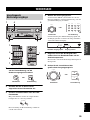 233
233
-
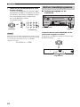 234
234
-
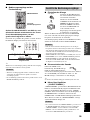 235
235
-
 236
236
-
 237
237
-
 238
238
-
 239
239
-
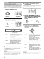 240
240
-
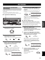 241
241
-
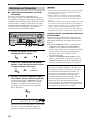 242
242
-
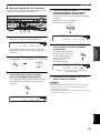 243
243
-
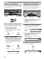 244
244
-
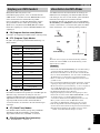 245
245
-
 246
246
-
 247
247
-
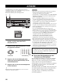 248
248
-
 249
249
-
 250
250
-
 251
251
-
 252
252
-
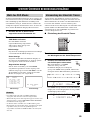 253
253
-
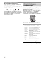 254
254
-
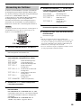 255
255
-
 256
256
-
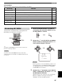 257
257
-
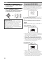 258
258
-
 259
259
-
 260
260
-
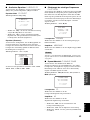 261
261
-
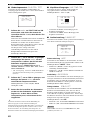 262
262
-
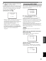 263
263
-
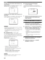 264
264
-
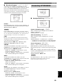 265
265
-
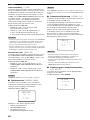 266
266
-
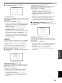 267
267
-
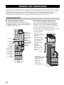 268
268
-
 269
269
-
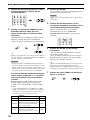 270
270
-
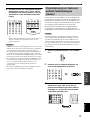 271
271
-
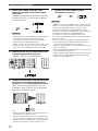 272
272
-
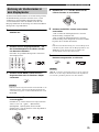 273
273
-
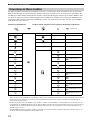 274
274
-
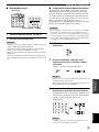 275
275
-
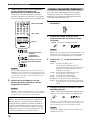 276
276
-
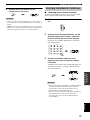 277
277
-
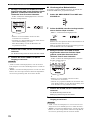 278
278
-
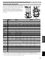 279
279
-
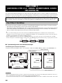 280
280
-
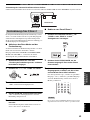 281
281
-
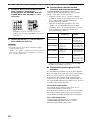 282
282
-
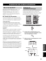 283
283
-
 284
284
-
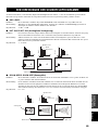 285
285
-
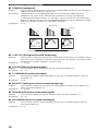 286
286
-
 287
287
-
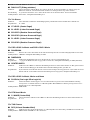 288
288
-
 289
289
-
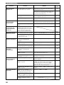 290
290
-
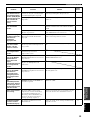 291
291
-
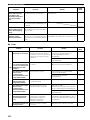 292
292
-
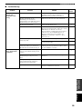 293
293
-
 294
294
-
 295
295
-
 296
296
-
 297
297
-
 298
298
-
 299
299
-
 300
300
-
 301
301
-
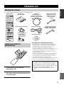 302
302
-
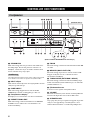 303
303
-
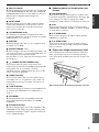 304
304
-
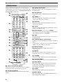 305
305
-
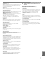 306
306
-
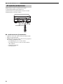 307
307
-
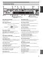 308
308
-
 309
309
-
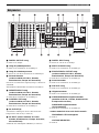 310
310
-
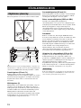 311
311
-
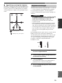 312
312
-
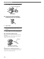 313
313
-
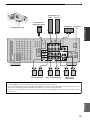 314
314
-
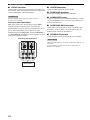 315
315
-
 316
316
-
 317
317
-
 318
318
-
 319
319
-
 320
320
-
 321
321
-
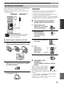 322
322
-
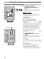 323
323
-
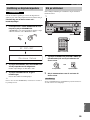 324
324
-
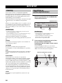 325
325
-
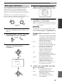 326
326
-
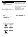 327
327
-
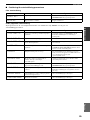 328
328
-
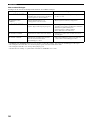 329
329
-
 330
330
-
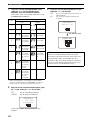 331
331
-
 332
332
-
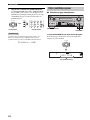 333
333
-
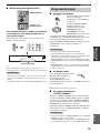 334
334
-
 335
335
-
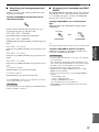 336
336
-
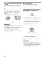 337
337
-
 338
338
-
 339
339
-
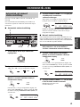 340
340
-
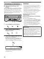 341
341
-
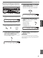 342
342
-
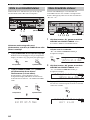 343
343
-
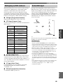 344
344
-
 345
345
-
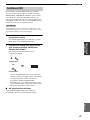 346
346
-
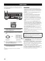 347
347
-
 348
348
-
 349
349
-
 350
350
-
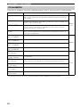 351
351
-
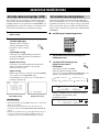 352
352
-
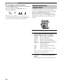 353
353
-
 354
354
-
 355
355
-
 356
356
-
 357
357
-
 358
358
-
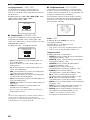 359
359
-
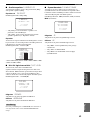 360
360
-
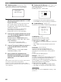 361
361
-
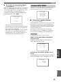 362
362
-
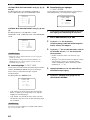 363
363
-
 364
364
-
 365
365
-
 366
366
-
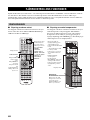 367
367
-
 368
368
-
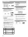 369
369
-
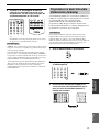 370
370
-
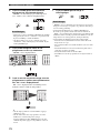 371
371
-
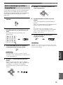 372
372
-
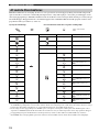 373
373
-
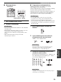 374
374
-
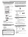 375
375
-
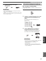 376
376
-
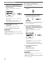 377
377
-
 378
378
-
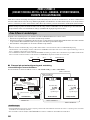 379
379
-
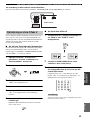 380
380
-
 381
381
-
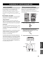 382
382
-
 383
383
-
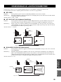 384
384
-
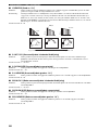 385
385
-
 386
386
-
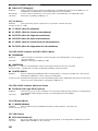 387
387
-
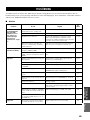 388
388
-
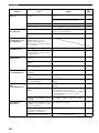 389
389
-
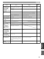 390
390
-
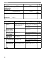 391
391
-
 392
392
-
 393
393
-
 394
394
-
 395
395
-
 396
396
-
 397
397
-
 398
398
-
 399
399
-
 400
400
-
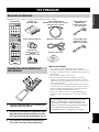 401
401
-
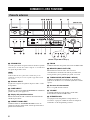 402
402
-
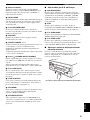 403
403
-
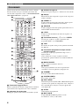 404
404
-
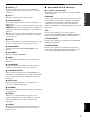 405
405
-
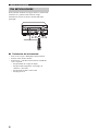 406
406
-
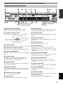 407
407
-
 408
408
-
 409
409
-
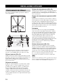 410
410
-
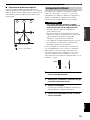 411
411
-
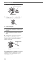 412
412
-
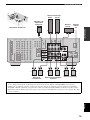 413
413
-
 414
414
-
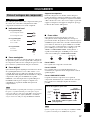 415
415
-
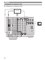 416
416
-
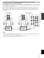 417
417
-
 418
418
-
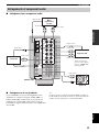 419
419
-
 420
420
-
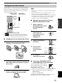 421
421
-
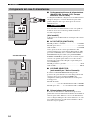 422
422
-
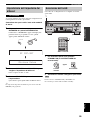 423
423
-
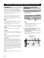 424
424
-
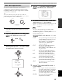 425
425
-
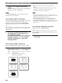 426
426
-
 427
427
-
 428
428
-
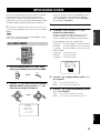 429
429
-
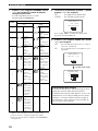 430
430
-
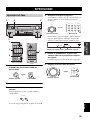 431
431
-
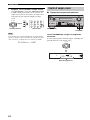 432
432
-
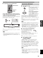 433
433
-
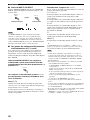 434
434
-
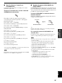 435
435
-
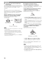 436
436
-
 437
437
-
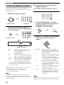 438
438
-
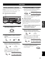 439
439
-
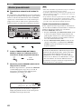 440
440
-
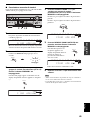 441
441
-
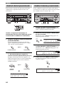 442
442
-
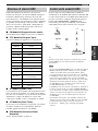 443
443
-
 444
444
-
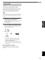 445
445
-
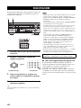 446
446
-
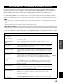 447
447
-
 448
448
-
 449
449
-
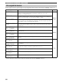 450
450
-
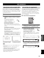 451
451
-
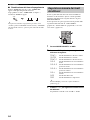 452
452
-
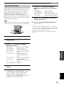 453
453
-
 454
454
-
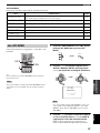 455
455
-
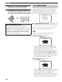 456
456
-
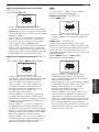 457
457
-
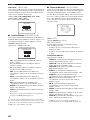 458
458
-
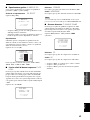 459
459
-
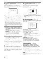 460
460
-
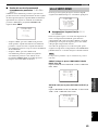 461
461
-
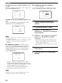 462
462
-
 463
463
-
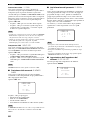 464
464
-
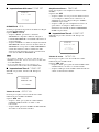 465
465
-
 466
466
-
 467
467
-
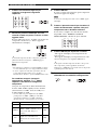 468
468
-
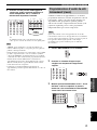 469
469
-
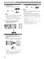 470
470
-
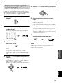 471
471
-
 472
472
-
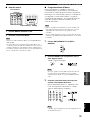 473
473
-
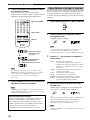 474
474
-
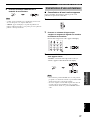 475
475
-
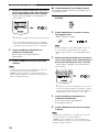 476
476
-
 477
477
-
 478
478
-
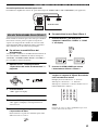 479
479
-
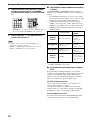 480
480
-
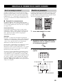 481
481
-
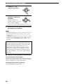 482
482
-
 483
483
-
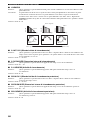 484
484
-
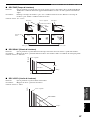 485
485
-
 486
486
-
 487
487
-
 488
488
-
 489
489
-
 490
490
-
 491
491
-
 492
492
-
 493
493
-
 494
494
-
 495
495
-
 496
496
-
 497
497
-
 498
498
-
 499
499
-
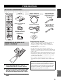 500
500
-
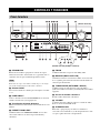 501
501
-
 502
502
-
 503
503
-
 504
504
-
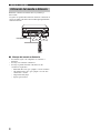 505
505
-
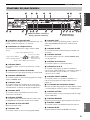 506
506
-
 507
507
-
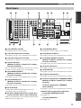 508
508
-
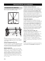 509
509
-
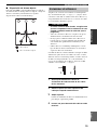 510
510
-
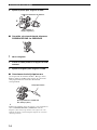 511
511
-
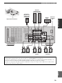 512
512
-
 513
513
-
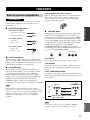 514
514
-
 515
515
-
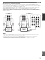 516
516
-
 517
517
-
 518
518
-
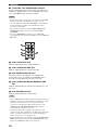 519
519
-
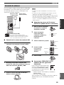 520
520
-
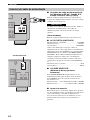 521
521
-
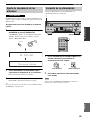 522
522
-
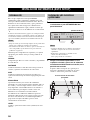 523
523
-
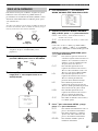 524
524
-
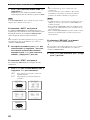 525
525
-
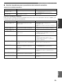 526
526
-
 527
527
-
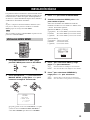 528
528
-
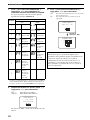 529
529
-
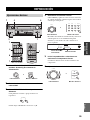 530
530
-
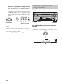 531
531
-
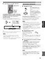 532
532
-
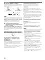 533
533
-
 534
534
-
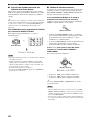 535
535
-
 536
536
-
 537
537
-
 538
538
-
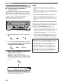 539
539
-
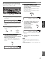 540
540
-
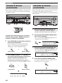 541
541
-
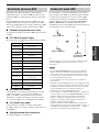 542
542
-
 543
543
-
 544
544
-
 545
545
-
 546
546
-
 547
547
-
 548
548
-
 549
549
-
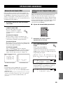 550
550
-
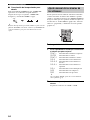 551
551
-
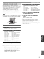 552
552
-
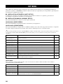 553
553
-
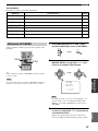 554
554
-
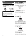 555
555
-
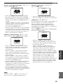 556
556
-
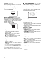 557
557
-
 558
558
-
 559
559
-
 560
560
-
 561
561
-
 562
562
-
 563
563
-
 564
564
-
 565
565
-
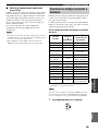 566
566
-
 567
567
-
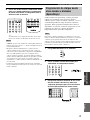 568
568
-
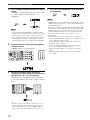 569
569
-
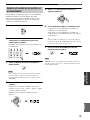 570
570
-
 571
571
-
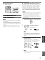 572
572
-
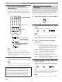 573
573
-
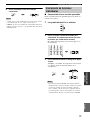 574
574
-
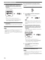 575
575
-
 576
576
-
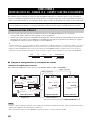 577
577
-
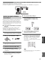 578
578
-
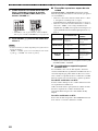 579
579
-
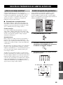 580
580
-
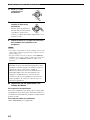 581
581
-
 582
582
-
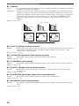 583
583
-
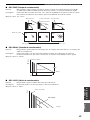 584
584
-
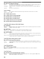 585
585
-
 586
586
-
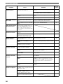 587
587
-
 588
588
-
 589
589
-
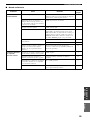 590
590
-
 591
591
-
 592
592
-
 593
593
-
 594
594
-
 595
595
-
 596
596
-
 597
597
-
 598
598
-
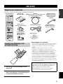 599
599
-
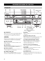 600
600
-
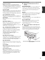 601
601
-
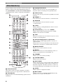 602
602
-
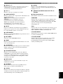 603
603
-
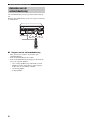 604
604
-
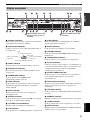 605
605
-
 606
606
-
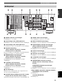 607
607
-
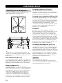 608
608
-
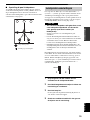 609
609
-
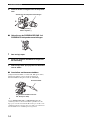 610
610
-
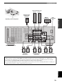 611
611
-
 612
612
-
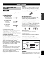 613
613
-
 614
614
-
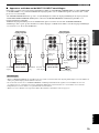 615
615
-
 616
616
-
 617
617
-
 618
618
-
 619
619
-
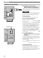 620
620
-
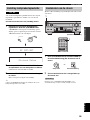 621
621
-
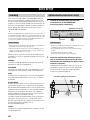 622
622
-
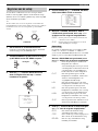 623
623
-
 624
624
-
 625
625
-
 626
626
-
 627
627
-
 628
628
-
 629
629
-
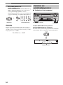 630
630
-
 631
631
-
 632
632
-
 633
633
-
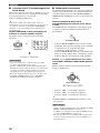 634
634
-
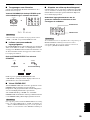 635
635
-
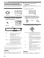 636
636
-
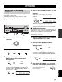 637
637
-
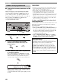 638
638
-
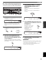 639
639
-
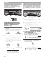 640
640
-
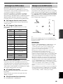 641
641
-
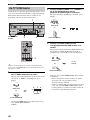 642
642
-
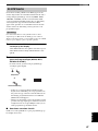 643
643
-
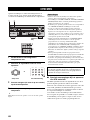 644
644
-
 645
645
-
 646
646
-
 647
647
-
 648
648
-
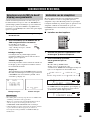 649
649
-
 650
650
-
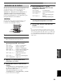 651
651
-
 652
652
-
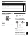 653
653
-
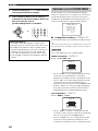 654
654
-
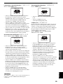 655
655
-
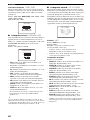 656
656
-
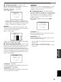 657
657
-
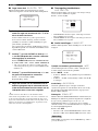 658
658
-
 659
659
-
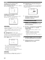 660
660
-
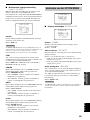 661
661
-
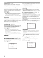 662
662
-
 663
663
-
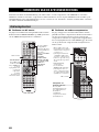 664
664
-
 665
665
-
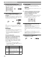 666
666
-
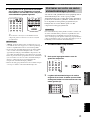 667
667
-
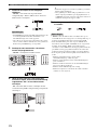 668
668
-
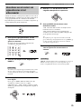 669
669
-
 670
670
-
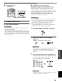 671
671
-
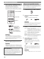 672
672
-
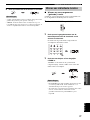 673
673
-
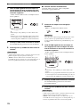 674
674
-
 675
675
-
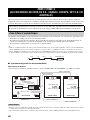 676
676
-
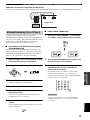 677
677
-
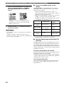 678
678
-
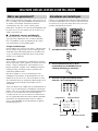 679
679
-
 680
680
-
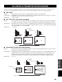 681
681
-
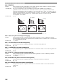 682
682
-
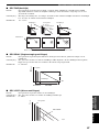 683
683
-
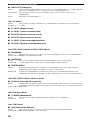 684
684
-
 685
685
-
 686
686
-
 687
687
-
 688
688
-
 689
689
-
 690
690
-
 691
691
-
 692
692
-
 693
693
-
 694
694
-
 695
695
-
 696
696
-
 697
697
-
 698
698
-
 699
699
-
 700
700


Diğer dillerde
- español: Yamaha RX-V1500 El manual del propietario
- français: Yamaha RX-V1500 Le manuel du propriétaire
- italiano: Yamaha RX-V1500 Manuale del proprietario
- svenska: Yamaha RX-V1500 Bruksanvisning
- Deutsch: Yamaha RX-V1500 Bedienungsanleitung
- English: Yamaha RX-V1500 Owner's manual
- dansk: Yamaha RX-V1500 Brugervejledning
- Nederlands: Yamaha RX-V1500 de handleiding
- română: Yamaha RX-V1500 Manualul proprietarului
İlgili Makaleler
-
Yamaha RX-V4600 - AV Receiver Kullanım kılavuzu
-
-
-
-
-
-
-
-
-