Brocade Communications Systems 6505 Hızlı başlangıç ​​Kılavuzu

Kategori
Oyuncaklar
Tip
Hızlı başlangıç ​​Kılavuzu

Bu kılavuz için de uygundur

Brocade 6505 QuickStart Guide
Complete the steps in this guide to install and set up your Brocade 6505 switch in a single-switch configuration using
EZSwitchSetup. See the Brocade 6505 Hardware Reference Manual and the Fabric OS Administrator’s Guide
if you want to choose a different setup.
Ensure that you have the items listed below. Write down the IP network values in the space provided.
Getting Ready
Fixed IP address (IPv4 or IPv6) for the switch (no DHCP server): __________________________________________________
Subnet mask value: ______________________________________________________________________________________
Default Gateway value: ___________________________________________________________________________________
Brocade switch World Wide Name (WWN): located on the switch ID pullout: ________________________________________
Ethernet connection (hub or switch) Ethernet and Fibre Channel Cables
EZSwitchSetup CD Setup computer
Host computer with an installed HBA Disk array
Standard screw driver Optical transceivers (SFPs)
Browser that allows pop-up windows
1
Powering up and connecting cables to the switch
3
Installing and starting EZSwitchSetup
2
1. Insert the EZSwitchSetup CD into the CD-ROM drive of your setup computer. The installer will autostart in about a minute.
2. Follow the EZSwitchSetup directions for installation. Installation will take a few minutes after you click OK.
3. Wait for EZSwitchSetup to start, which should happen automatically after it is installed.
For Windows and Linux instructions, refer to the EZSwitchSetup Administrator’s Guide.
4. On the EZSwitchSetup Introduction screen, choose the option that matches your setup configuration:
Ethernet connection. This option uses the Ethernet LAN connection you will use for running EZSwitchSetup Manager.
Direct connection to the switch with a serial cable.
Most users will find it more convenient to use the Ethernet connection.
5. Click Next. The Connect Cables screen is displayed.
4. Click Next.
If you chose to use the Ethernet connection, the Discover Switch screen is displayed. Enter the switch WWN, following
the instructions on the Discover Switch screen. After completing switch discovery, the Set Switch IP Address screen
is displayed.
If you chose to use the serial port connection, the Set Switch IP Address screen is immediately displayed.
The Connect Cables screen shows you the connections you need to make.
1. Connect the power cord to the switch and to a power
source (1). The power and status LEDs display amber then
green. This can take from one to three minutes.
2. Connect the switch and the setup computer to the
same LAN, using Ethernet cables (3, 5) and an Ethernet
hub or switch (2). Be sure the Ethernet hub or switch is
connected to a power source (6).
3. If you want to use a serial connection for setup, connect
your setup computer COM port (7) to the serial port on the
switch, using the serial cable shipped with the switch (4).
The serial connection settings are as follows:
Bits per second: 9600
Databits: 8
Parity: none
Stop bits: 1
Flow control: none
®
1
2
7
5
3
6
4
Setting the switch IP address
4
1. Enter the required information on the Set Switch IP Address screen.
2. If prompted to install Active X or a version of the Java runtime environment, do so. Reboot the setup computer, if required.
3. Click Next.
The Confirm IP Address screen is displayed.
4. Click Next to confirm the addresses.
A Continue Configuration screen is displayed.
5. Click Continue with EZManager.
1. Install the SFP+ transceivers in the Fibre Channel ports on the switch to match the ports shown onscreen.
2. Make the physical connections to your host and storage devices. Match the physical connections shown on the
Configure Ports and Connect Devices screen.
3. The Finish screen will display this message: “Congratulations - you’ve successfully completed the setup!” If you used the
serial connection for setup, you can remove the serial cable.
Additional configuration options, such as custom zoning, are available from EZManager. See the EZSwitchSetup
Administrator’s Guide for more information on custom zoning, and other switch configuration and management options.
Set the switch password
5
1. Click Next on the EZManager Welcome to Switch Configuration screen.
The Set Parameters screen is displayed.
2. Create a new administrator account password in the Set Parameters screen.
3. Enter a new name for the switch (optional step).
4. Adjust the date and time for your time zone (optional step).
5. Click Next.
Configure the zones and perform device selection
6
1. Select Typical Zoning on the Select Zoning screen and click Next.
Typical Zoning is the default zone configuration.
2. Enter the number and types of devices that you are connecting to the switch on the Device Selection screen.
EZSwitchSetup uses these values to automatically configure the ports on your switch.
Connect devices
7
The Connect Devices screen displays a graphical representation of the switch with the device connections based on the
information that you entered when you configured zones and performed device selection. The screen will show all physical
connections as missing until you connect the devices that you specified.
a. The 16 Gbps SFP+ transceivers have a long pull tab and no latching
wire bail. Remove any protector plugs from the SFP+ transceivers you
are going to use, and position and insert each SFP+ transceiver as
required (right side up in the top row of ports and upside down in the
bottom row of ports). Use the pull tab on the 16 Gbps SFP+ tranceivers
to help push the transceiver into the port.
If you are using 16 Gbps SFP+ transceivers, you may want to connect
the cable to the SFP+ first, and then insert them into the port as a unit.
If you are using 8 Gbps SFP+ transceivers, close the latching wire bail.
b. Repeat for the other ports.
a. Remove plastic protector caps from the Fibre Channel cable ends (if any),
and position the cable connector so that it is oriented correctly.
b. Insert the cable connector into the SFP+ until it is firmly seated and
the latching mechanism clicks.
c. The Configure Ports and Connect Devices screen shows missing,
valid, and invalid connections as you cable the switch. Note that it
can take up to 15 seconds for the connection to display as a valid
connection. Verify that the connections are all green and click Next.
®
!
Brocade, the B-wing symbol, BigIron, DCX, Fabric OS, FastIron, NetIron, SAN Health, ServerIron, and TurboIron are registered trademarks, and AnyIO,
Brocade Assurance, Brocade NET Health, Brocade One, CloudPlex, MLX, VCS, VDX, and When the Mission Is Critical, the Network Is Brocade are trademarks of
Brocade Communications Systems, Inc., in the United States and/or in other countries. Other brands, products, or service names mentioned are or may be
trademarks or service marks of their respective owners.
© 2011 Brocade Communications Systems, Inc. All Rights Reserved.
53-1002536-01
!
*53-1002536-01*
Brocade 6505 快速入门指南
完成本指南中的步骤,使用 EZSwitchSetup 在单交换机配置下,安装和配置 Brocade 6505 交换机。
如果您想要选择不同的设置,请参阅《Brocade 6505 硬件参考手册》和《Fabric OS 管理员指南》。
确保您拥有以下所列的各项。在提供的空白处写下 IP 网络值。
准备工作
交换机(无 DHCP 服务器)的固定 IP 地址(IPv4 IPv6): __________________________________________________
子网掩码值: ______________________________________________________________________________________
默认网关值: ___________________________________________________________________________________
Brocade 交换机全局名称 (WWN):位于交换机 ID 拉环上: ________________________________________
以太网连接(集线器或交换机) 以太网和光纤信道电缆
EZSwitchSetup CD 安装计算机
安装有 HBA 的主机 磁盘阵列
标准螺丝刀 光学收发器 (SFP)
允许弹出窗口的浏览器
1
启动和连接电缆至交换机
3
安装和启动 EZSwitchSetup
2
1. EZSwitchSetup CD 盘插入设置计算机的光驱。安装程序将在大约一分钟后自动运行。
2. 按照 EZSwitchSetup 安装说明操作。单击 OK(确定)之后,安装将需要几分钟时间。
3. 等候 EZSwitchSetup 启动,在安装后它应会自动启动。
有关 Windows Linux 说明,请参阅 EZSwitchSetup Administrator’s Guide EZSwitchSetup 管理员指南》)。
4. EZSwitchSetup 介绍屏幕,选择与您的安装配置匹配的选项:
以太网连接。该选项使用您将用于运行 EZSwitchSetup Manager 的以太网 LAN 连接。
使用串行电缆直接连接到交换机。
大多数用户会发现,使用以太网连接更方便。
5. 单击 Next(下一步)。这将会显示 Connect Cables(连接电缆)屏幕。
4. 单击 Next(下一步)。
如果选择使用以太网连接,将会显示 Discover Switch(查找交换机)屏幕。 按照 Discover Switch(查找交换机)
屏幕上的说明输入交换机的 WWN。在完成交换机查找之后,将会显示 Set Switch IP Address(设置交换机 IP 地址)
屏幕。
如果选择使用串行端口连接,将会立即显示 Set Switch IP Address(设置交换机 IP 地址)屏幕。
Connect Cables(连接电缆)屏幕显示您需要进行的连接。
1. 使用电源线连接交换机和电源 (1)
电源和状态 LED 指示灯会先显示琥珀色,
然后变为绿色。这可能需要一至三分钟。
2. 使用以太网电缆 3 5 和以太网集线器或交
换机 (2) 将交换机和设置计算机连接到同一个 LAN
请确保将以太网集线器或交换机连接到电源 (6)
3. 如果您想使用串行连接进行设置,请使用交换
机随附的串行电缆 (4) 将设置计算机 COM 端口 (7)
连接到交换机上的串行端口。串行连接设置如下所示:
每秒位数:9600
数据位:8
奇偶校验:无
停止位:1
流量控制:
®
1
2
7
5
3
6
4
设置交换机 IP 地址
4
1. Set Switch IP Address(设置交换机 IP 地址)屏幕中输入需要的信息。
2. 如果提示安装 Active X 或某个 Java runtime environment(运行时环境)版本,请按提示操作。
如果需要,重新启动安装计算机。
3. 单击 Next(下一步)。
显示 Confirm IP Address(确认 IP 地址)屏幕。
4. 单击 Next(下一步)确认地址。
显示 Continue Configuration(继续配置)屏幕。
5. 单击 Continue with EZManager(继续 EZManager)。
1. 在交换机的光纤信道端口中安装 SFP+ 收发器,以匹配屏幕上显示的端口。
2. 实现到主机和存储设备的物理连接。匹配 Configure Ports and Connect Devices(配置端口和连接设备)
屏幕上所示的物理连接。
3. Finish(完成)屏幕显示此信息:“Congratulations - you’ve successfully completed the setup!”(恭喜 - 您已成功
完成设置!)。如果您使用的是串行连接来设置,您可以卸下串行电缆。
EZManager 还提供其它配置选项,例如自定义分区。有关自定义分区、其它交换机配置和管理选项的更多信息,
请参阅《EZSwitchSetup 管理员指南》。
设置交换机密码
5
1. EZManager Welcome to Switch Configuration(欢迎使用交换机配置)屏幕中单击 Next(下一步)。
显示 Set Parameters(设置参数)屏幕。
2. Set Parameters(设置参数)屏幕中创建一个新的管理员帐户密码。
3. 为交换机输入新名称(可选步骤)。
4. 调整时区的日期和时间(可选步骤)。
5. 单击 Next(下一步)。
配置区域和执行设备选择
6
1. Select Zoning(选择分区)屏幕上选择 Typical Zoning(典型分区),然后单击 Next(下一步)。
典型分区是默认区域配置。
2. Device Selection(设备选择)屏幕上输入您连接到交换机的设备的数量和类型。
EZSwitchSetup 将使用这些值在交换机上自动配置端口。
连接设备
7
Connect Devices(连接设备)屏幕根据您在配置分区和执行设备选择时输入的信息,
显示交换机的图示以及设备连接。该屏幕会将所有的物理连接显示为缺失,
直至您连接了所指定的设备。
a. 16 Gbps SFP+ 收发器具有较长的拉环,没有闭锁线箍。
移除要使用的 SFP+ 收发器上的任何保护塞,按照要求找
到位置并插入每个 SFP+ 收发器(顶部一排端口应右侧朝上,
底部一排端口应上下倒置)。使用 16 Gbps SFP+ 收发器上
的拉环帮助将收发器推入到端口中。
如果您使用 16 Gbps SFP+ 收发器,可能要先将电缆连接
SFP+ 收发器,然后再将它们作为一个整体插入到端口中。
如果您使用 8 Gbps SFP+ 收发器,请闭合闭锁线箍。
b. 对其它端口重复这些步骤。
a. 从光纤信道末端卸下塑料保护帽(如果有),然后对准电缆连接器,
以使它方向正确。
b. 将电缆连接器插入 SFP+,直到其牢固就位,闭锁机制卡扣到位。
c. 在为交换机布线时 Configure Ports and Connect Devices
(配置端口和连接设备)屏幕会显示连接缺失、有效和无效。
请注意:连接可能需要最长 15 秒时间才能显示为有效连接。
确认连接全部都为绿色,然后单击 Next(下一步)。
®
!
BrocadeB 翼形标志、BigIronDCXFabric OSFastIronNetIronSAN HealthServerIron TurboIron 是 注册商标,AnyIO
Brocade AssuranceBrocade NET HealthBrocade OneCloudPlexMLXVCSVDX When the Mission Is Critical, the Network Is Brocade
Brocade Communications Systems, Inc. 在美国和/或其它国家/地区的商标。文中提及的其它品牌、产品或服务名称是,或可能是
各自所有者的商标或服务标志。
© 2011 Brocade Communications Systems, Inc. 保留所有权利。
53-1002536-01
!
*53-1002536-01*
Brocade 6505 快速啟動指南
確認已備妥下列事項。將 IP 網路值填寫在下列的空格中。
準備開始
交換機的固定 IP 位址 (IPv4 IPv6) ( DHCP 伺服器的情況)_________________________________________________
子網路遮罩值:__________________________________________________________________________________________
預設閘道值:___________________________________________________________________________________________
Brocade 交換機全域名稱 (WWN):位於交換機 ID 標籤上:____________________________________________________
乙太網路連接(集線器或交換機) 乙太網路和光纖通道纜線
EZSwitchSetup 光碟 設定電腦
安裝了 HBA 的主機電腦 磁碟陣列
標準螺絲起子 光學收發器 (SFP)
允許彈出視窗的瀏覽器
1
打開電源並將纜線連接至交換機
3
安裝並啟動 EZSwitchSetup
2
「連接纜線 Connect Cables」畫面會顯示您必須連接的連線。
®
1
2
7
5
3
6
4
1. 將電源線與交換機和電源 (1) 連接。電源和狀態
LED 燈會先變成琥珀色再變成綠色。這個程序大約
需要 13 分鐘。
2. 使用乙太網路纜線 (35) 與乙太網路集線器或交換
(2) 將交換機與要設定的電腦連接到同一個區域網
路上。確認乙太網路集線器或交換機連接到電源 (6)
3. 如果您要使用序列連線進行安裝,請使用與交換機
(4) 內附的序列纜線,將您的安裝電腦 COM 連接埠
(7) 連接至交換機上的序列埠。序列連線的設定如下:
每秒傳輸位元:9600
資料位元:8
同位檢查:無
停止位元:1
流程控制:無
4. 按一下下一步 (Next)
如果您選擇使用乙太網路連接,將顯示「探索交換機 (Discover Switch)」畫面。依照「探索交換機
(Discover Switch)」畫面上的指示輸入交換機 WWN。交換機探索完成後,會顯示「設定交換機 IP 位址
(Set Switch IP Address)」畫面。
如果您選擇使用序列連接埠連接,會立即顯示「設定交換機 IP 位址 (Set Switch IP Address)」畫面。
請執行本指南中的步驟安裝 Brocade 6505 交換機並利用 EZSwitchSetup 將交換機設定為單一交換組態。
如果您想選擇不同的設定方式,請參閱 Brocade 6505 硬體參考手
冊與 Fabric OS
硬體參考手冊
管理員指南
1. EZSwitchSetup 光碟插入要設定的電腦光碟機中。一分鐘後安裝程式將自動啟動。
2. 依照 EZSwitchSetup 指示進行安裝。按下「確定 (OK)」後,將耗費幾分鐘時間進行安裝。
3. 等待 EZSwitchSetup 開始執行,它會在完成安裝後自動執行。
有關 Windows Linux 的說明,請參閱 EZSwitchSetup
4. EZSwitchSetup 簡介畫面中,請選擇符合您的設定組態的選項:
乙太網路連接。此選項使用乙太網路區域連線連接,您將可用來執行 EZSwitchSetup Manager
使用序列纜線直接連接交換機。
大多數使用者會發現使用乙太網路連線更為便利。
5. 按一下下一步 Next。隨即顯示「連接纜線 Connect Cables」畫面。
管理員指南
設定交換機 IP 位址
4
1. SFP+ 收發器安裝於交換機上的光纖通道連接埠以符合螢幕上所顯示的連接埠。
設定交換機密碼
5
設定區域並執行裝置選擇
6
連接裝置
7
®
!
© 2011 Brocade Communications Systems, Inc. 版權所有,翻印必究。
53-1002536-01
!
*53-1002536-01*
1. 在「設定交換機 IP 位址 (Set Switch IP Address)」畫面中輸入必要的資訊。
2. 出現提示要求安裝 Active X 或安裝某一版本 Java 執行時期環境時,請進行安裝。 如有需要,請重新啟動設定的電腦。
3. 按一下下一步 (Next)
隨即顯示「確認 IP 位址 (Confirm IP Address)」畫面。
4. 按一下下一步 (Next) 以確認位址。
隨即顯示「繼續設定 (Continue Configuration)」畫面。
5. 按一下「繼續使用 EZManager (Continue with EZManager)」。
1. 在「EZManager 歡迎使用交換機設定 (EZManager Welcome to Switch Configuration)」畫面中按一下下一步 (Next)
隨即顯示「設定參數 (Set Parameters)」畫面。
2. 在「設定參數 (Set Parameters)」畫面中建立新的管理員帳戶密碼。
3. 輸入新的交換機名稱 (選擇性步驟)。
4. 調整您的時區的日期與時間 (選擇性步驟)。
5. 按一下下一步 (Next)
1. 在「選擇區域 (Select Zoning)」 畫面中選擇「典型區域 (Typical Zoning)」,再按一下下一步 (Next)
典型區域 (Typical Zoning) 是預設的區域組態。
2. 在您要連線之交換機的「裝置選擇 (Device Selection)」畫面上輸入裝置類型和裝置編號。
EZSwitchSetup 會使用這些值自動組態交換機的連接埠。
「連接裝置 (Connect Devices)」畫面會依據您在設定區域並執行裝置選擇時所輸入的資訊,以圖形化的方式顯示交換機
與裝置的連線。此畫面將會顯示所有實體連線都是中斷的,直到您連接所指定的裝置為止。
a. 16 Gbps SFP+ 收發器有一個長的拉啟式標籤且沒有閂鎖纜線橫桿。
拆除您將使用的 SFP+ 收發器上的任何保護器掛件,並依需要置放與
插入每一個 SFP+ 收發器 (右邊朝上放在上排連接埠,上面朝下放在
下排連接埠)。使用 16 Gbps SFP+ 收發器上的拉啟式標籤,將收發
器推入連接埠中。
如果您使用的是 16 Gbps SFP+ 收發器,您可能想先將纜線連接
SFP+,然後將它們當作裝置插入連接埠中。
如果您要使用 8 Gbps SFP+ 收發器,請關閉閂鎖纜線橫桿。
b. 在其他連接埠上重複執行此動作。
a. 將光纖通道纜線端的塑膠保護蓋 (如果有的話) 取下,然後調整纜線
接頭的位置以使其方向正確。
b. 將纜線接頭插入 SFP+ 直到確實固定,而且閂鎖機構發出喀嗒聲。
c. 當纜線連接到交換機時,「組態連接埠與連接裝置 (Configure Ports
and Connect Devices)」畫面上會顯示遺失的、有效的與無效的連接。
請注意,待連接顯示為有效連接大約需要 15 秒鐘。請確認所有連接
都呈現綠色並按「下一步 (Next)」。
2. 將主機與儲存裝置的實體連接。將「組態連接埠與連接裝置 (Configure Ports and Connect Devices)」畫面上
顯示的實體連接配對。
BrocadeB-wing 符號、BigIronDCXFabric OSFastIronNetIronSAN HealthServerIron TurboIron Brocade Communications Systems, Inc.
的註冊商標;AnyIOBrocade AssuranceBrocade NET HealthBrocade OneCloudPlexMLXVCSVDX When the Mission Is Critical,the Network
Is Brocade Brocade Communications Systems, Inc. 在美國和/或其他國家/地區的商標。上述提到的其他品牌、產品或服務名稱則為或可能
為其各自所有者的商標或服務標誌。
3. (Finish)」畫面將顯示此訊息:「恭喜 - 您已成功完成設定!( Congratulations - you’ve successfully completed
the setup!)」,如果您使用序列連線進行設定,則可移除序列纜線。
其他組態選項 (如自訂區域) 可透過 EZManager 取得。請參閱 EZSwitchSetup 瞭解更多有關自訂區域與其
他交換機組態和管理選項的資訊。
管理員指南
Guide de démarrage rapide Brocade 6505
Complétez les étapes de ce guide pour installer et mettre en place votre commutateur Brocade 650 en une configuration
de commutateur unique à l'aide de EZSwitchSetup. Voir le Manuel de Référence du matériel Brocade 6505 et le
Guide de l'administrateur Fabric OS pour choisir une configuration différente.
Vérifiez que vous disposez des éléments répertoriés ci-dessous. Prenez note des valeurs du réseau IP dans l'espace réservé.
Préparation
Adresse IP corrigée (IPv4 ou IPv6) pour le commutateur (pas de serveur DHCP) : ___________________________________
Valeur du masque de sous-réseau : ___________________________________________________ _____________________
Valeur de passerelle par défaut :_______________________ ____________________________________________________
Nom universel (WWN) du commutateur Brocade : situé sur la languette d'ID du commutateur : _______________________
Connexion Ethernet (concentrateur ou commutateur) Câbles Ethernet et Fibre Channel
CD EZSwitchSetup Configuration de l'ordinateur
Ordinateur hôte avec un HBA installé Matrices de disques
Tournevis standard Émetteurs-récepteurs optiques (SFP)
Navigateur qui permet l'affichage de fenêtres pop-up
1
Mise sous tension du commutateur et connexion des câbles
3
Installation et démarrage de EZSwitchSetup
2
1. Insérez le CD EZSwitchSetup dans le lecteur CD-ROM de votre ordinateur de configuration. Le programme d'installation
démarrera automatiquement dans environ une minute.
2. Suivez les instructions EZSwitchSetup pour l'installation. L'installation prendra quelques minutes après que vous aurez
cliqué sur OK.
3. Attendez que EZSwitchSetup démarre, ce qui devrait se produire automatiquement une fois le programme installé.
Pour consulter les instructions Windows et Linux, voir le Guide de l'administrateur EZSwitchSetup.
4. Sur l'écran de présentation de EZSwitchSetup, choisissez l'option qui correspond à votre configuration :
Connexion Ethernet. Cette option utilise la connexion de réseau local Ethernet que vous utiliserez pour exécuter le
Gestionnaire EZSwitchSetup.
Connexion directe au commutateur avec un câble de série.
La plupart des utilisateurs préféreront se servir de la connexion Ethernet.
5. Cliquez sur Suivant. L'écran Connecter les câbles s'affiche.
4. Cliquez sur Suivant.
Si vous choisissez d'utiliser la connexion Ethernet, l'écran Commutateur détecté s'affiche. Entrez le WWN du
commutateur, en suivant les instructions affichées à l'écran Commutateur détecté. Une fois la détection de
commutateur terminée, l'écran Définir l'adresse IP du commutateur de configuration s'affiche.
Si vous choisissez d'utiliser la connexion port série, l'écran Définir l'adresse IP du commutateur de configuration
s'affiche immédiatement.
L'écran Connecter les câbles vous indique les connexions à établir.
1. Connectez le cordon d'alimentation au commutateur, puis
à une source d'alimentation (1). Les voyants d'alimentation
et d'état s'allument en orange puis en vert. Cela peut prendre
d'une à trois minutes.
2. Connectez le commutateur et l'ordinateur de configuration
au même réseau local, en utilisant des câbles Ethernet (3, 5)
et un concentrateur ou un commutateur Ethernet (2).
Assurez-vous que le concentrateur ou commutateur Ethernet
est connecté à une source d'alimentation (6).
3. Pour une configuration avec connexion série, connectez le
port COM (7) de votre ordinateur de configuration au port
série du commutateur en utilisant le câble série livré avec le
commutateur (4). Les paramètres de connexion série sont
les suivants:
Bits par seconde : 9600
Bits de données : 8
Parité : aucune
Arrêt bits : 1
Contrôle du flux : aucun
®
1
2
7
5
3
6
4
Définition de l'adresse IP du commutateur
4
1. Entrez les renseignements nécessaires sur l'écran Définir l'adresse IP du commutateur.
2. Si vous êtes invité à installer Active X ou une version de l'environnement d'exécution Java runtime, faites-le.
Redémarrez la configuration de l'ordinateur, si nécessaire.
3. Cliquez sur Suivant.
L'écran de confirmation de l'adresse IP s'affiche.
4. Cliquez sur Suivant pour confirmer les adresses.
Un écran Poursuivre la configuration s'affiche.
5. Cliquez sur Continuer en utilisant EZManager.
1. Installez les émetteurs-récepteurs SFP+ dans les ports Fibre Channel du commutateur pour faire correspondre les ports
affichés à l'écran.
2. Etablissez les connexions physiques à votre hôte et à vos périphériques de stockage. Faites correspondre les connexions
physiques de l' écran Configurer des ports et connecter des périphériques.
3. L'écran final affiche ce message : “Congratulations - you’ve successfully completed the setup!” («Félicitations - vous avez
réussi la configuration ! »). Si vous avez utilisé la connexion série pour la configuration, vous pouvez retirer le câble série.
Des options de configurations supplémentaires, telle que la personnalisation du zonage, sont disponibles à partir de
EZManager. Voir le Guide de l'administrateur EZSwitchSetup pour plus d'informations sur la personnalisation du zonage,
et pour d'autres configurations de commutateur et options de gestion.
Définir le mot de passe du commutateur
5
1. Cliquez sur Suivant sur l'écran de Bienvenue à la configuration du commutateur d'EZManager.
L'écran Configurer les paramètres s'affiche.
2. Créez un nouveau mot de passe pour le compte administrateur sur l'écran Configurer les paramètres.
3. Entrez un nouveau nom pour le commutateur (étape facultative).
4. Réglez la date et l'heure selon votre zone horaire (étape facultative).
5. Cliquez sur Suivant.
Configurer les zones et procéder à une sélection de périphériques
6
1. Sélectionnez Zonage type sur l'écran Sélectionner le zonage, puis cliquez sur Suivant.Le zonage type est la configuration
de zones par défaut.
2. Entrez le nombre et les types de périphériques que vous connectez au commutateur à l'écran Sélection de périphériques.
EZSwitchSetup utilise ces valeurs pour configurer automatiquement les ports sur votre commutateur.
Branchement des périphériques
7
L'écran Connecter les périphériques affiche une représentation graphique du commutateur avec les connexions de
périphériques selon les informations entrées lors de la configuration des zones et la sélection des paramètres.
L'écran affiche toutes les connexions physiques comme manquantes tant que les périphériques que vous avez
spécifiés ne sont pas connectés.
a. Les émetteurs-récepteurs SFP+ 16 Gbits/s ont une languette de retrait
et aucun loquet de verrouillage. Supprimez toutes les fiches de protection
des émetteurs-récepteurs SFP+ que vous allez utiliser, puis positionnez et
insérez chaque émetteur-récepteur SFP+ comme requis (à l'endroit dans la
rangée supérieure de ports et à l'envers dans la rangée inférieure de ports).
Utilisez la languette de retrait des émetteurs-récepteurs SFP+ 16 Gbits/s
pour pousser les émetteurs-récepteurs dans les ports.
Si vous utilisez des émetteurs-récepteurs SFP+ 16 Gbits/s, connectez le
câble au SFP+ d'abord, puis insérez-les dans le port comme une unité.
Si vous utilisez des émetteurs-récepteurs SFP+ 8 Gb/s, fermez le loquet
de verrouillage.
b. Répétez cette procédure pour les autres ports.
a. Retirez les capuchons de protection en plastique des extrémités de câble
Fibre Channel (s'il y a lieu) et disposez le connecteur de câble de façon à
l'orienter correctement.
b. Insérez le connecteur de câble dans le SFP+ jusqu'à ce qu'il soit bien
installé et que le mécanisme de verrouillage s'enclenche.
c. L'écran Configurer des ports et connecter des périphériques affiche les
connexions manquantes, valides et invalides pendant le câblage du
commutateur. Remarquez que vous devrez peut-être patienter jusqu'à 15
secondes pour que la connexion s'affiche comme valide connexion.
Vérifiez que les connexions sont toutes vertes, puis cliquez sur Suivant.
®
!
Brocade, le symbole B-wing, BigIron, DCX, OS Fabric, FastIron, NetIron, SAN Health, ServerIron, et TurboIron sont des marques déposées, et AnyIO,
Brocade Assurance, Brocade NET Health, Brocade One, CloudPlex, MLX, VCS, VDX et When the Mission Is Critical, the Network Is Brocade sont des marques de
Brocade Communications Systems, Inc., aux États-Unis et/ou dans d'autres pays. Les autres marques, produits ou noms de services mentionnés sont ou peuvent
être des marques ou des marques de service de leurs propriétaires respectifs.
© 2011 Brocade Communications Systems, Inc. Tous droits réservés.
53-1002536-01
!
*53-1002536-01*
Brocade 6505-Schnellstarthandbuch
Folgen Sie den Schritten dieser Anleitung, um Ihren Brocade Switch 6505 mit EZSwitchSetup in einer Einzel-Switch-
Konfiguration zu installieren und einzurichten. Falls Sie eine andere Art des Setup wünschen, finden Sie Informationen
hierzu im Brocade 6505 Hardware Referenzhandbuch und dem Administratorhandbuch zu Fabric OS.
Vergewissern Sie sich, dass alle unten aufgeführten Artikel vorhanden sind. Notieren Sie in den dafür vorgesehenen
Feldern die IP-Netzwerk-Angaben.
Vor dem Start
Feste IP-Adresse (IPv4 oder IPv6) für den Switch (kein DHCP-Server): _____________________________________________
Subnetzmaske: _________________________________________________________________________________________
Standard-Gateway: ______________________________________________________________________________________
World Wide Name (WWN) des Brocade-Switches: befindet sich auf dem Auszug mit der Bezeichnung „Switch ID“: _________
Ethernet-Verbindung (Hub oder Switch) Ethernet- und Fibre-Channel-Kabel
EZSwitchSetup CD Setup-Computer
Host-Computer mit installiertem HBA Festplatten-Array
Standard-Schraubendreher Optische Transceiver (SFPs)
Browser, der die Anzeige von Popup-Fenstern ermöglicht
1
Einschalten und Verbinden der Kabel mit dem Switch
3
Installieren und Starten von EZSwitchSetup
2
1. Legen Sie die EZSwitchSetup-CD in das CD-ROM-Laufwerk des Setup-Computers. Das Installationsprogramm startet
automatisch innerhalb von ca. einer Minute.
2. Folgen Sie den Installationsanweisungen von EZSwitchSetup. Die Installation dauert noch einige Minuten, nachdem
Sie auf OK geklickt haben.
3. Warten Sie, bis EZSwitchSetup startet. Dieser Vorgang sollte nach der Installation automatisch ausgeführt werden.
Windows- und Linux-Anweisungen finden Sie im EZSwitchSetup-Administratorhandbuch.
4. Wählen Sie auf dem Bildschirm „EZSwitchSetup Introduction“ (EZSwitchSetup – Einführung) die Option, die Ihrer
Setupkonfiguration entspricht:
„Ethernet connection“ (Ethernet-Verbindung). Diese Option nutzt die Ethernet-LAN-Verbindung, die Sie zum Ausführen
des EZSwitchSetup Manager verwenden.
„Direct connection to the switch with a serial cable“ (Direkte Verbindung mit dem Switch über ein serielles Kabel).
Die meisten Benutzer halten die Verwendung der Ethernet-Verbindung für komfortabler.
5. Klicken Sie auf „Next“ (Weiter). Der Bildschirm „Connect Cables“ (Kabel verbinden) wird angezeigt.
4. Klicken Sie auf „Next“ (Weiter).
Falls Sie die Ethernet-Verbindung wählen, wird der Bildschirm „Discover Switch“ (Switch erkennen) angezeigt. Geben Sie
entsprechend den Anweisungen auf dem Bildschirm „Discover Switch“ (Switch erkennen) den WWN des Switch ein. Nach
Abschluss der Switch-Erkennung wird der Bildschirm „Set Switch IP Address“ (IP-Adresse des Switch festlegen) angezeigt.
Wenn Sie sich für die Verwendung der seriellen Schnittstellenverbindung entschieden haben, wird umgehend der
Bildschirm „Set Switch IP Address“ (IP-Adresse des Switch festlegen) angezeigt.
Auf dem Bildschirm „Connect Cables“ (Kabel verbinden) werden die erforderlichen Verbindungen dargestellt.
1. Verbinden Sie das Stromkabel mit dem Switch und
einer Stromquelle (1). Die Betriebs- und Status-LEDs
leuchten zunächst gelb, dann grün. Dies kann ein
bis drei Minuten dauern.
2. Schließen Sie den Switch und den Setup-Computer
mithilfe von Ethernet-Kabeln (3, 5) und einem Ethernet-Hub
oder Switch (2) an dasselbe LAN an. Stellen Sie sicher, dass
der Ethernet-Hub oder der Switch an eine Stromversorgung
angeschlossen ist (6).
3. Wenn Sie eine serielle Verbindung für das Setup
verwenden möchten, schließen Sie den COM-Port Ihres
Setup-Computers (7) an den seriellen Anschluss auf dem
Switch an. Verwenden Sie dazu das serielle Kabel, das im
Lieferumfang Ihres Switches enthalten ist (4). Die
Einstellungen für die serielle Verbindung lauten wie folgt:
„Bits per second“ (Bit pro Sekunde): 9600
„Databits“ (Datenbits): 8
„Parity“ (Parität): none (keine)
„Stop bits“ (Stopp-Bits): 1
„Flow control“ (Datenflusssteuerung): none (keine)
®
1
2
7
5
3
6
4
Festlegen der IP-Adresse des Switch
4
1. Geben Sie die erforderlichen Daten auf dem Bildschirm „Set Switch IP Address“ (IP-Adresse des Switch festlegen) ein.
2. Folgen Sie ggf. der Aufforderung, Active X oder eine Version der Java Runtime-Umgebung zu installieren.
Führen Sie anschließend, falls erforderlich, einen Neustart des Setup-Computers durch.
3. Klicken Sie auf „Next“ (Weiter).
Daraufhin wird der Bildschirm „Confirm IP Address“ (IP-Adresse bestätigen) angezeigt.
4. Klicken Sie auf „Next“ (Weiter), um die Adressen zu bestätigen.
Nun wird der Bildschirm „Continue Configuration“ (Konfiguration fortsetzen) angezeigt.
5. Klicken Sie auf „Continue with EZManager“ (Mit EZManager fortfahren).
1. Installieren Sie die SFP+-Transceiver auf den Fibre Channel-Ports auf dem Switch entsprechend der auf dem
Bildschirm angegebenen Ports.
2. Stellen Sie die physischen Verbindungen mit Ihrem Host und den Speichergeräten her. Stellen Sie die in den Bildschirmen
„Configure Ports“ (Ports konfigurieren) und „Connect Devices“ (Geräte verbinden) gezeigten physischen Verbindungen her.
3. Auf dem Bildschirm „Finish“ (Fertig stellen) wird die folgende Meldung angezeigt: „Congratulations - you’ve successfully
completed the setup!“ (Herzlichen Glückwunsch - Sie haben das Setup erfolgreich abgeschlossen!). Wenn Sie die serielle
Verbindung für das Setup verwendet haben, können Sie das serielle Kabel jetzt entfernen.
Über den EZManager können Sie auf weitere Konfigurationsoptionen wie benutzerdefinierte Zoneneinteilung zugreifen.
Weitere Informationen zur benutzerdefinierten Zoneneinteilung und anderen optionen für die Konfiguration und Verwaltung
von Switches finden Sie im EZSwitchSetup-Administratorhandbuch.
Festlegen des Switch-Kennworts
5
1. Klicken Sie auf dem EZManager-Bildschirm „Welcome to Switch Configuration“ (Willkommen bei der
Switch-Konfiguration) auf „Next“ (Weiter).
Daraufhin wird der Bildschirm „Set Parameters“ (Parameter festlegen) angezeigt.
2. Erstellen Sie auf dem Bildschirm „Set Parameters“ (Parameter festlegen) ein neues Kennwort für das Administratorkonto.
3. Geben Sie einen neuen Namen für den Switch ein (optionaler Schritt).
4. Passen Sie Datum und Uhrzeit an Ihre Zeitzone an (optionaler Schritt).
5. Klicken Sie auf „Next“ (Weiter).
Konfigurieren von Zonen und Ausführen der Geräteauswahl
6
1. Wählen Sie die Option Typical Zoning“ (Typische Zoneneinteilung) auf dem Bildschirm „Select Zoning“
(Zoneneinteilung auswählen) aus, und klicken Sie auf „Next“ (Weiter).
Typical Zoning“ (Typische Zoneneinteilung) ist die Standard-Zonenkonfiguration.
2. Geben Sie im Bildschirm „Device Selection“ (Geräteauswahl) die Anzahl und Typen von Geräten ein, die Sie mit
dem Switch verbinden. EZSwitchSetup konfiguriert mithilfe dieser Angaben automatisch die Ports auf Ihrem Switch.
Verbinden von Geräten
7
Auf dem Bildschirm „Connect Devices“ (Geräte verbinden) wird eine grafische Darstellung des Switch mit seinen
Geräteverbindungen dargestellt. Als Grundlage dieser Darstellung dienen die Informationen, die Sie im Rahmen der
Konfiguration der Zoneneinteilung und der Geräteauswahl eingegeben haben. Dieser Bildschirm zeigt alle physischen
Verbindungen so lange als fehlend an, bis Sie die von Ihnen angegebenen Geräte verbunden haben.
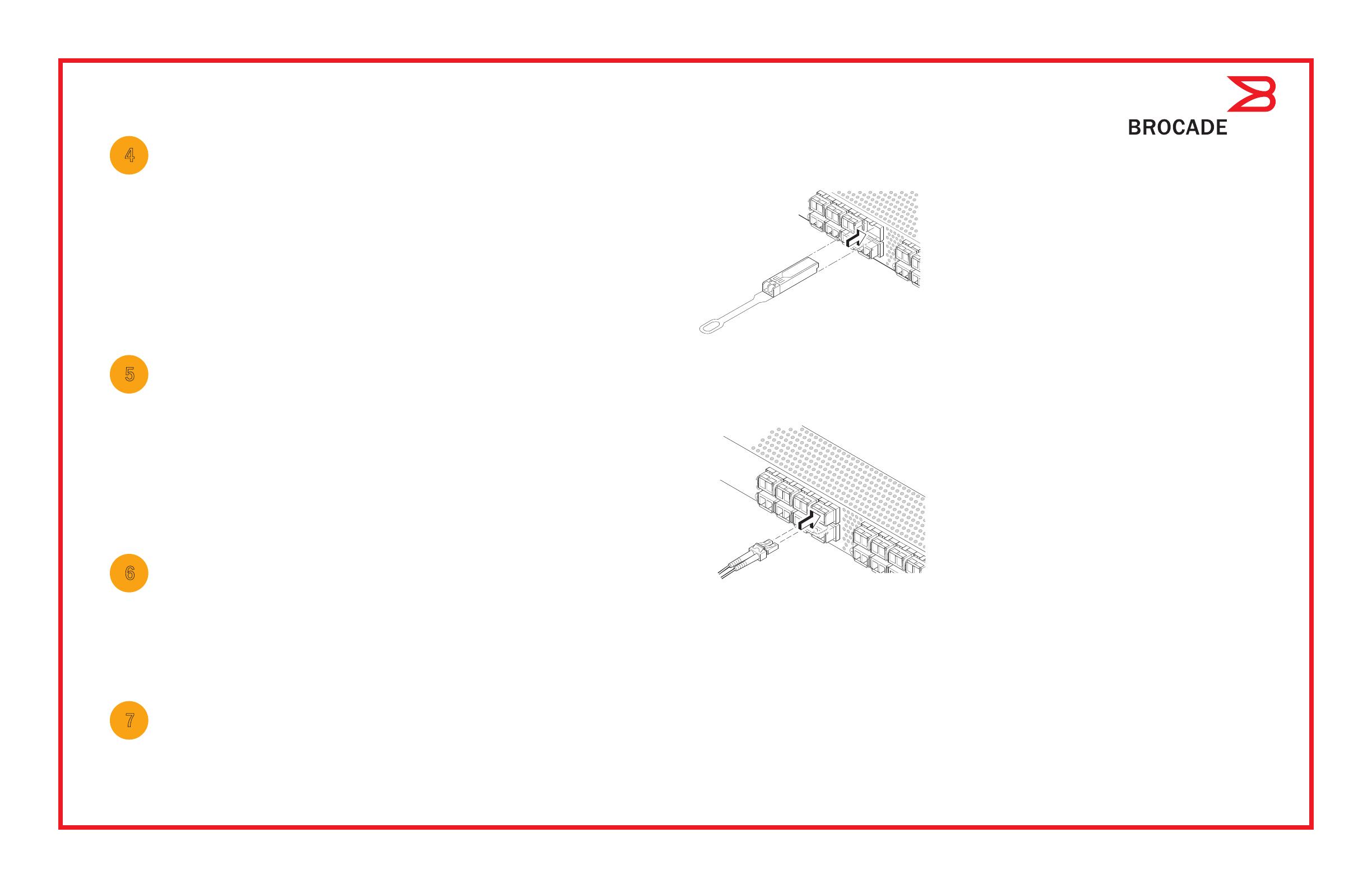
a. Die 16Gb/s-SFP+-Transceiver besitzen eine lange Ziehlasche und keine
Verriegelungsdrahtbügel. Entfernen Sie Schutzstecker von den SFP+-
Transceivern, die Sie benutzen wollen, positionieren Sie jeden SFP+-
Transceiver wie benötigt und setzen Sie ihn ein (rechte Seite nach oben in
der oberen Portreihe und umgedreht in der unteren Portreihe). Schieben
Sie die 16Gb/s-SFP+-Transceiver mithilfe der Ziehlasche in den Port.
Falls Sie 16Gb/s-SFP+-Transceiver verwenden, kann es hilfreich sein,
zuerst die Kabel mit dem SFP+ zu verbinden und sie dann als
Einheit in den Port einzusetzen.
Wenn Sie 8Gb/s-SFP+-Transceiver verwenden, schließen Sie
den Verriegelungsdrahtbügel.
b. Wiederholen Sie diese Schritte für alle anderen Ports.
a. Entfernen Sie die Kunststoffschutzkappen von den Fibre-Channel-
Kabelenden (falls vorhanden), und positionieren Sie den Stecker des
Kabels so, dass er korrekt ausgerichtet ist.
b. Fügen Sie den Stecker in den SFP+ ein, bis er fest sitzt und der
Verriegelungsmechanismus hörbar einrastet.
c. Der Bildschirm „Configure Ports“ (Ports konfigurieren) und „Connect
Devices“ (Geräte verbinden) zeigt fehlende, korrekte und inkorrekte
Verbindungen an, wenn Sie den Switch verkabeln. Beachten Sie, dass es
bis zu 15 Sekunden dauern kann bis eine korrekte Verbindung angezeigt
wird. Prüfen Sie, ob alle Verbindungen grün sind und klicken Sie auf
„Next“ (Weiter).
®
!
Brocade, das B-wing-Symbol, BigIron, DCX, Fabric OS, FastIron, NetIron, SAN Health, ServerIron und TurboIron sind eingetragene Marken, AnyIO,
Brocade Assurance, Brocade NET Health, Brocade One, CloudPlex, MLX, VCS, VDX, und 'When the Mission Is Critical, the Network Is Brocade' sind Marken von
Brocade Communications Systems, Inc. in den USA und/oder anderen Ländern. Weitere genannte Namen von Marken, Produkten oder Dienstleistungen sind Marken
oder Dienstleistungsmarken ihrer jeweiligen Eigentümer oder können Marken oder Dienstleistungsmarken ihrer jeweiligen Eigentümer sein.
© 2011 Brocade Communications Systems, Inc. Alle Rechte vorbehalten.
53-1002536-01
!
*53-1002536-01*
Panduan Mulai Cepat Brocade 6505
Selesaikan langkah di dalam panduan ini untuk memasang dan menyetel sakelar Brocade 6505 Anda dalam konfigurasi satu
sakelar menggunakan EZSwitchSetup. Lihat Panduan Referensi Perangkat Keras Brocade 6505 dan Panduan Administrator
Fabric OS jika Anda ingin memilih penyetelan yang berbeda.
Pastikan Anda telah memiliki item-item yang tercantum di bawah ini. Tuliskan nilai jaringan IP di dalam ruang yang disediakan.
Persiapan
Alamat IP tetap (IPv4 atau IPv6) untuk sakelar (tidak ada server DHCP): __________________________________________
Nilai subnet mask: ______________________________________________________________________________________
Nilai Default Gateway: ___________________________________________________________________________________
World Wide Name (WWN) sakelar Brocade: terletak di label ID sakelar: __________________________________________
Koneksi Ethernet (hub atau sakelar) Kabel Fibre Channel dan Ethernet
CD EZSwitchSetup Komputer penyetelan
Komputer host dengan HBA terinstal Rangkaian disk
Obeng standar Transceiver optik (SFP)
Browser yang memungkinkan adanya jendela sembul (pop-up)
1
Menyalakan dan menyambungkan kabel ke sakelar
3
Menginstal dan memulai EZSwitchSetup
2
1. Masukkan CD EZSwitchSetup ke dalam drive CD-ROM komputer penyetelan Anda. Installer akan dimulai otomatis
dalam waktu sekitar satu menit.
2. Ikuti arahan EZSwitchSetup untuk penginstalan. Penginstalan akan memerlukan waktu beberapa menit setelah
Anda mengeklik OK.
3. Tunggulah hingga EZSwitchSetup mulai dijalankan, yang seharusnya akan dimulai secara otomatis setelah EZSwitchSetup terinstal.
Untuk instruksi Windows dan Linux, bacalah Panduan Administrator EZSwitchSetup.
4. Di layar Introduction (Pendahuluan) EZSwitchSetup, pilih opsi yang cocok dengan konfigurasi pengaturan Anda:
Sambungan Ethernet. Opsi ini menggunakan sambungan LAN Ethernet yang akan Anda gunakan untuk menjalankan
EZSwitchSetup Manager.
Sambungan langsung ke sakelar dengan kabel seri.
Sebagian besar pengguna merasa lebih mudah menggunakan sambungan Ethernet.
5. Klik Next (Selanjutnya). Layar Connect Cables (Sambungkan Kabel) akan ditampilkan.
4. Klik Next (Selanjutnya).
Jika Anda memilih menggunakan sambungan Ethernet, layar Discover Switch (Temukan Sakelar) akan ditampilkan.
Masukkan WWN sakelar, sesuai dengan instruksi di layar Discover Switch (Temukan Sakelar). Setelah menyelesaikan
penemuan sakelar, layar Set Switch IP Address (Atur Alamat IP Sakelar) akan ditampilkan.
Jika Anda memilih menggunakan sambungan port seri, layar Set Switch IP Address (Atur Alamat IP Sakelar)
segera ditampilkan.
Layar Connect Cables (Sambungkan Kabel) menampilkan sambungan yang perlu Anda buat.
1. Sambungkan kabel daya ke sakelar dan ke sumber
daya (1). LED status dan daya akan menyala kuning lalu
hijau. Prosedur ini bisa memakan waktu satu hingga
tiga menit.
2. Sambungkan sakelar dan komputer penyetelan ke LAN
yang sama, dengan menggunakan kabel Ethernet (3, 5) dan
sakelar atau hub Ethernet (2). Pastikan sakelar atau hub
Ethernet tersambung ke sumber daya (6).
3. Jika Anda ingin menggunakan sambungan seri untuk
penyetelan, sambungkan port COM komputer penyetelan
(7) Anda ke port seri di sakelar, dengan menggunakan kabel
seri yang disertakan bersama sakelar (4). Pengaturan
sambungan seri adalah sebagai berikut:
Bit per detik: 9600
Databit: 8
Paritas: tidak ada
Bit stop: 1
Kontrol aliran: tidak ada
®
1
2
7
5
3
6
4
Mengatur alamat IP sakelar
4
1. Masukkan informasi yang diperlukan pada layar Set Switch IP Address (Atur Alamat IP Sakelar).
2. Jika Anda diminta menginstal Active X atau versi lingkungan runtime Java, lakukanlah. Reboot komputer penyetelan,
jika diperlukan.
3. Klik Next (Selanjutnya).
Layar Confirm IP Address (Konfirmasikan Alamat IP) akan ditampilkan.
4. Klik Next (Selanjutnya) untuk mengonfirmasikan alamat.
Layar Continue Configuration (Lanjutkan Konfigurasi) akan ditampilkan.
5. Klik Continue with EZManager (Lanjutkan dengan EZManager).
1. Pasang port transceiver SFP+ di port Fibre Channel pada sakelar untuk memadankan port yang ditunjukkan di layar.
2. Buat sambungan fisik ke perangkat penyimpanan dan host Anda. Cocokkan dengan sambungan fisik yang ditampilkan di
layar Configure Ports and Connect Devices (Konfigurasikan Port dan Sambungkan Perangkat).
3. Layar Finish (Selesai) akan menampilkan pesan ini: “Congratulations - you’ve successfully completed the setup!”
("Selamat - Anda telah berhasil menyelesaikan penyetelan!") Jika Anda menggunakan sambungan seri penyetelan,
Anda dapat melepaskan kabel seri.
Opsi konfigurasi tambahan, seperti penzonaan kesukaan, tersedia di EZManager. Bacalah Panduan Administrator
EZSwitchSetup untuk informasi lebih lanjut tentang penzonaan kesukaan, opsi manajemen serta konfigurasi sakelar lain.
Atur kata sandi sakelar
5
1. Klik Next (Selanjutnya) pada layar Welcome to Switch Configuration (Selamat Datang di Konfigurasi Sakelar) EZManager.
Layar Set Parameters (Atur Parameter) akan ditampilkan.
2. Buat kata sandi akun administrator yang baru dalam layar Set Parameters (Atur Parameter).
3. Masukkan nama baru untuk sakelar (langkah opsional).
4. Sesuaikan tanggal dan waktu untuk zona waktu Anda (langkah opsional).
5. Klik Next (Selanjutnya).
Konfigurasikan zona dan lakukan pemilihan perangkat
6
1. Pilih Typical Zoning (Penzonaan Umum) pada layar Select Zoning (Pilih Penzonaan) dan klik Next (Selanjutnya).
Typical Zoning adalah konfigurasi zona bawaan.
2. Masukkan jumlah dan tipe perangkat yang akan Anda sambungkan ke sakelar di layar Device Selection (Pilihan Perangkat).
EZSwitchSetup menggunakan nilai-nilai ini untuk mengonfigurasikan port di sakelar Anda secara otomatis.
Menyambungkan perangkat
7
Layar Connect Devices (Sambungkan Perangkat) menampilkan representasi grafis sakelar dengan sambungan perangkat
berdasarkan informasi yang telah Anda masukkan ketika mengonfigurasikan zona dan melakukan pemilihan perangkat.
Layar ini akan menunjukkan bahwa semua sambungan fisik tidak ditemukan hingga Anda menyambungkan perangkat yang
Anda tentukan.
a. Transceiver SFP+ 16 Gbps memiliki tab penarik yang panjang dan tidak
memiliki gagang kawat slot. Lepaskan segala sumbat pelindung dari
transceiver SFP+ yang akan Anda gunakan, dan posisikan serta sisipkan
setiap transceiver SFP+ sesuai dengan yang diperlukan(sisi kanan
menghadap ke atas pada baris port teratas dan menghadap ke bawah di
baris bawah port). Gunakan tab penarik pada transceiver SFP+ 16 Gbps
untuk membantu mendorong transceiver ke dalam port.
Jika Anda menggunakan transceiver SFP+ 16 Gbps, pertama-tama
Anda dapat menghubungkan kabel ke SFP+, dan kemudian masukkan ke
dalam port sebagai sebuah unit.
Jika Anda menggunakan transceiver SFP+ 8 Gbps, tutuplahgagang kawat slot.
b. Ulangi untuk port lain.
a. Lepaskan tutup pelindung plastik dari ujung kabel Fibre Channel (jika ada),
dan posisikan konektor kabel sehingga diarahkan dengan benar.
b. Masukkan konektor kabel ke dalam SFP+ hingga terpasang dengan kuat
dan mekanisme slotnya telah terpasang tepat.
c. Layar Configure Ports and Connect Devices (Konfigurasikan Port dan
Sambungkan Perangkat) menunjukkan bahwa sambungan hilang, valid,
dan tidak valid ketika Anda menghubungkan kabel sakelar. Perhatikan
bahwa mungkin dibutuhkan waktu hingga 15 detik hingga sambungan
ditampilkan sebagai sambungan yang valid. Periksalah apakah
sambungan sudah hijau semua, lalu klik Next (Selanjutnya).
®
!
Brocade, simbol B-wing, BigIron, DCX, Fabric OS, FastIron, NetIron, SAN Health, ServerIron, dan TurboIron merupakan merek dagang terdaftar, dan AnyIO,
Brocade Assurance, Brocade NET Health, Brocade One, CloudPlex, MLX, VCS, VDX, dan When the Mission Is Critical, Network Is Brocade merupakan merek dagang
terdaftar dari Brocade Communications Systems, Inc., di AS dan/atau negara lain. Merek, produk, atau nama layanan lain yang disebutkan merupakan atau mungkin
merupakan merek dagang atau merek layanan pemiliknya masing-masing.
© 2011 Brocade Communications Systems, Inc. Hak Cipta Dilindungi Undang-undang.
53-1002536-01
!
*53-1002536-01*
Brocade 6505 クイックスタートガイド
このガイドにある EZSwitchSetup の手順を完了して、Brocade 6505 スイッチをインストールし、シングルスイッチ構成に
セットアップします。別のセットアップをご希望の場合は、『
Brocade 6505 Hardware Reference Manual』(Brocade 6505
ハードウェアリファレンスマニュアル)および『 Fabric OS Administrator’s Guide』(ファブリック OS 管理者ガイド)を
参照してください
以下にリストされているアイテムが手元あることを確認してください。
IP ネットワークの値を該当する場所に書き込みます。
準備
スイッチの固定 IP アドレス(IPv4
または
IPv6 DHCP
サーバーなし):
________________________________________________
サブネットマスクの値:
____________________________________________________________________________________________
デフォルトゲートウェイの値:
______________________________________________________________________________________
Brocade スイッチのワールドワイド名(WWN):スイッチの引き出し式 ID ラベルに記載:
_______________________________
ーサネット接続(ハブまたはスイッチ) イーサネットおよびファイバチャネル用ケーブル
EZSwitchSetup CD セットアップするコンピュータ
HBA がインストールされたホストコンピュータ ディスクアレイ
標準ドライバ 光学トランシーバ(
SFP
ポップアップウィンドウを許可するように設定したブラウザ
1
スイッチへの電源投入とケーブルの接続
3
EZSwitchSetup のインストールと起動
2
1. セットアップするコンピュータの CD-ROM ドライブに EZSwitchSetup CD を挿入します。
1 分程でインストーラが自動的にスタートします
2. EZSwitchSetup の手順に従ってインストールします。OK をクリックした後、インストールは数分で完了します。
3. EZSwitchSetup が起動するのを待ちます。通常は CD の挿入後に自動的に起動されます。
Windows および Linux 向け手順については、『EZSwitchSetup Administrator’s Guide』(EZSwitchSetup
管理者ガイド)を参照してください。
4. 画面上に EZSwitchSetup 導入画面が表示されたら、お使いのセットアップ設定に合うオプションを選択します。
Ethernet connection(イーサネット接続)。このオプションは、EZSwitchSetup Manager の実行に使用することになる
イーサネット LAN 接続を使用します。
Direct connection to the switch with a serial cable(シリアルケーブルを用いたスイッチへの直接接続)。
ほとんどのユーザーには、イーサネット接続を利用がより便利です。
5. Next(次へ)をクリックします。Connect Cables(ケーブル接続)の画面が表示されます。
4. Next(次へ)をクリックします。
イーサネット接続を使用する場合、Discover Switchスイッチの検出)画面が表示されます。スイッチの WWN を入力し、
Discover Switchスイッチの検出)画面の手順に従います。スイッチの検出が完了すると、 Set Switch IP Address
(スイッチ IP アドレスの設定)画面が表示されます。
シリアルポート接続を選択する場合には、スイッチの IP アドレスの設画面がすぐに表示されます。
ケーブルの接続画面には、行う必要のある接続内容が表示されます。
1. 電源ケーブルをスイッチおよび電源に接続します(1)。
電源およびステータス
LED が橙色に点灯し、次に緑色
になります。 これには
13 分かかる場合があります。
2. ーサネットケーブルを使って、スイッチとセットアップ
用コンピュータを同じ
LAN に接続し(35)、イーサネット用
ハブまたはスイッチも接続します(
2)。このイーサネット用
ハブまたはスイッチが電源に接続されていることを確認します 。
3. シリアル接続を使ってセットアップを行う場合は、
セットアップ用コンピュータの
COM ポート(7)をスイッチの
シリアルポートに接続します。この接続には、スイッチに同梱の
シリアルケーブルを使用してください(
4)。シリアル接続の
設定は次のとおりです。
送速度
bps):9600
データビット:8
パリティ:なし
ストップビット:1
フロー制御:なし
®
1
2
7
5
3
6
4
スイッチ IP アドレスの設定
4
1. Set Switch IP Address
(スイッチ IP アドレスの設定)画面で必要な情報を入力します。
2. Active X
または特定のバージョンの
Java
ランタイム環境をインストールするプロンプトが表示された場合は、
それに従ってインストールしてください。必要に応じて、セットアップ用コンピュータを再起動します。
3. Next
(次へ)をクリックします。
Confirm IP Address
IP アドレスの確認)画面が表示されます。
4. Next
(次へ)をクリックして、アドレスを確認します。
設定の継続画面が表示されます。
5. Continue with EZManager
EZManager
を続行)をクリックします。
1.
画面に表示されているポートと一致するように、
SFP+
トランシーバをスイッチのファイバチャネルポートに取り付けます。
2.
ホストとストレージデバイスに物理的な接続を施します。物理的な接続が
Configure Ports and Connect Devices
(ポートの
設定およびデバイスの接続)画面と同じになるようにします。
3.
Finish
(完了)
画面に「
Congratulations - you’ve successfully completed the setup!
」(おめでとうございます、セットアップが
正しく完了しました)というメッセージが表示されます。セットアップにシリアル接続を使用した場合は、シリアル
ケーブルを取り外すことができます。
EZManager
では、カスタムゾーニングなどの追加設定オプションを利用できます。 カスタムゾーニング、およびその他の
スイッチ設定や管理オプションの詳細については『
EZSwitchSetup Administrator’s Guide
』(
EZSwitchSetup
管理者ガイド)
を参照してください。
スイッチパスワードの設定
5
1. EZManager
Welcome to Switch Configuration
(スイッチ設定へようこそ)画面で、
Next
(次へ)をクリックします。
Set Parameters
(パラメータの設定)画面が表示されます。
2.
Set Parameters
(パラメータの設定)画面で、システム管理者アカウント用の新規パスワードを作成します。
3.
スイッチの新しい名前を入力します(オプション)。
4.
お住まいのタイムゾーンに合わせて日付と時刻を調整します(オプション)。
5.
Next
(次へ)をクリックします。
ゾーンの設定とデバイス選択の実施
6
1.
Select Zoning
(ゾーニングの選択)画面で、
Typical Zoning
(一般的なゾーニング)を選択し、
Next
(次へ)をクリックします。
Typical Zoning
(一般的なゾーニング)はデフォルトのゾーン設定です。
2.
Device Selection
(デバイスの選択)画面で、スイッチに接続するデバイスの数とタイプを入力します。
EZSwitchSetup
はこれらの値を使用して、スイッチ上のポートを自動的に設定します。
デバイスの接続
7
ゾーン設定およびデバイス選択で入力された情報に基づいて、
Connect Devices
(デバイスの接続)画面に、
スイッチとデバイス接続の状況がグラフ表示されます。指定されたデバイスが実際に接続されるまでは、
画面上の物理的接続はすべて「
Missing
」(欠落)と表示されます。
a. 16 Gbps SFP+
トランシーバには長いプルタブがあり、ラッチ用ワイヤー
ハンドルはありません。使用するすべての
SFP+
トランシーバから保護
プラグを外し、指示の通りに各
SFP+
トランシーバを配置して挿入します
(ポートの最上列では表側を上にし、ポートの下部列では逆さにします)。
16 Gbps SFP+
トランシーバのプルタブを使用してトランシーバをポートに
押し入れます。
16 Gbps SFP+
トランシーバを使用する場合、最初にケーブルを
SFP+
接続してからそれらをまとめてポートに挿入します
8 Gbps SFP+
トランシーバを使用する場合は、ラッチ式のワイヤ留め具を
閉じます。
b.
他のポートについても同じ作業を繰り返してください。
a.
ファイバチャネルケーブルの先端にプラスティックの保護キャップが付
けられている場合は、それらを取り外した後、ケーブルのコネクタを正
しい向きに配置します。
b.
ケーブルコネクタが
SFP+
内にしっかりと装着され、ラッチ機構が働いて
カチッと音がするまでケーブルを
SFP+
内に挿入します。
c.
スイッチにケーブルを接続するごとに、
Configure Ports and Connect
Devices
(ポートの設定およびデバイスの接続)画面に、
missing
(欠落)、
valid
(有効)、および
invalid
(無効)の接続と表示されます。接続が
有効であると表示されるまでに、最高
15
秒かかる場合があるのでご注意
ください。接続がすべて緑色であることを確認し、
Next
(次へ)を
クリックします。
®
!
Brocade B-wing
シンボル、
BigIronDCXFabric OSFastIronNetIronSAN HealthServerIron
および
TurboIron
は米国およびその他の国における
Brocade Communications Systems, Inc.
の登録商標であり
AnyIO
Brocade Assurance
Brocade NET Health
Brocade One
CloudPlex
MLX
VCS
VDX
および
When the Mission Is Critical
Network Is Brocade
は米国およびその他の国における
Brocade Communications Systems, Inc.
の商標です。
この文書で使用されるその他のブランド、製品、またはサービス名は、それぞれの権利所有者に帰属する商標または役務商標です。
© 2011
すべての著作権は
Brocade Communications Systems Inc.
にあります。
53-1002536-01
!
*53-1002536-01*
Brocade 6505 빠른 시작 안내서
아래에 나열된 항목이 있는지 확인합니다. 제공된 공간에 IP 네트워크 값을 기록합니다.
준비하기
스위치(DHCP 서버 없음)에 대한 고정 IP 주소(IPv4 또는 IPv6): _________________________________________________
서브넷 마스크 값: ______________________________________________________________________________________
기본 게이트웨이 값: ___________________________________________________________________________________
Brocade 스위치 월드 와이드 이름(WWN): 스위치 ID 페이지에 있음: ________________________________________
이더넷 연결(허브 또는 스위치) 이더넷 및 파이버 채널 케이블
EZSwitchSetup CD 설치 컴퓨터
HBA가 설치된 호스트 컴퓨터 디스크 어레이
표준 십자 드라이버 광 트랜시버(SFP)
팝업 창을 허용하는 브라우저
1
전원 켜기 및 스위치에 케이블 연결
3
EZSwitchSetup 설치 및 시작
2
4. Next (다음)를 클릭합니다.
이더넷 연결을 사용하도록 선택하는 경우 Discover Switch (스위치 검색) 화면이 나타납니다.
Discover Switch (스위치 검색) 화면의 지침에 따라 스위치 WWN을 입력합니다. 스위치 검색을 완료하면
Set Switch IP Address (스위치 IP 주소 설정) 화면이 나타납니다.
직렬 포트 연결을 사용하도록 선택하는 경우 Set Switch IP Address (스위치 IP 주소 설정) 화면이 나타납니다.
Connect Cables (케이블 연결) 화면에 사용자가 연결해야 하는 항목이 나타납니다.
1. 스위치와 전원에 전원 코드를 연결합니다(1).
전원 및 상태 LED가 황색으로 표시된 후 녹색으로
표시됩니다. 약 1분에서 3분이 소요될 수 있습니다.
2. 이더넷 케이블(3 5)과 이더넷 허브 또는
스위치(2)를 사용하여 스위치 및 설치 컴퓨터를
동일한 LAN에 연결합니다. 이더넷 허브 또는 스위치가
전원에 연결되어 있는지 확인합니다(6).
3. 직렬 연결 방식으로 설정하려는 경우 스위치(4)와
함께 제공된 직렬 케이블을 사용하여 설치 컴퓨터 COM
포트(7)를 스위치의 직렬 포트에 연결합니다. 직렬 연결
설정은 다음과 같습니다.
초당 비트: 9600
데이터 비트: 8
패리티: 없음
정지 비트: 1
흐름 제어: 없음
®
1
2
7
5
3
6
4
1. 설치 컴퓨터의 CD-ROM 드라이브에 EZSwitchSetup CD를 삽입합니다. 약 1분 후에 설치 프로그램이 자동으로
시작됩니다.
2. EZSwitchSetup의 설치 지침을 따릅니다. OK(확인)를 클릭한 후 설치하는 데 몇 분 정도 소요됩니다.
3. 설치 후 관련 절차가 자동 진행되므로 EZSwitchSetup을 시작하려면 잠시 기다리십시오.
Windows Linux 지침을 보려면 EZSwitchSetup
4. EZSwitchSetup Introduction (EZSwitchSetup 소개) 화면에서 사용자의 설정 구성과 일치하는 옵션을 선택합니다.
이더넷 연결 이 옵션은 EZSwitchSetup 관리자를 실행하는 데 사용되는 이더넷 LAN 연결을 사용합니다.
직렬 케이블을 사용하여 스위치에 직접 연결합니다.
이더넷 연결을 사용하면 대부분의 사용자가 더욱 쉽게 작업을 수행할 수 있습니다.
5. Next (다음)를 클릭합니다. Connect Cables (케이블 연결) 화면이 나타납니다.
관리자 설명서를 참조하십시오.
EZSwitchSetup을 사용하여 단일 스위치 구성에 Brocade 6505 스위치를 설치하고 설정하려면 이 안내서의
단계를 완료합니다. 다른 설정을 선택하려면
참조하십시오.
Brocade 6505 하드웨어 참조 매뉴얼 및 Fabric OS 관리자 설명서를
스위치 IP 주소 설정
4
1. Set Switch IP Address (스위치 IP 주소 설정) 화면에 필요한 정보를 입력합니다.
2. Active X 또는 Java 런타임 환경 버전을 설치하라는 메시지가 나타나면 설치하십시오. 필요한 경우
설치 컴퓨터를 재부팅합니다.
3. Next (다음)를 클릭합니다.
Confirm IP Address (IP 주소 확인) 화면이 나타납니다.
4. Next (다음)를 클릭하여 주소를 확인합니다.
Continue Configuration (계속 구성) 화면이 나타납니다.
5. Continue with EZManager (EZManager를 사용하여 계속)을 클릭합니다.
1. 스위치의 파이버 채널 포트에 SFP+ 트랜스시버를 설치하여 화면에 표시되는 포트와 일치시킵니다.
2. 호스트 및 저장 장치에 물리적 연결을 수행합니다. Configure Ports and Connect Devices (포트 구성 및 장치 연결)
화면에 표시되는 물리적 연결과 일치시킵니다.
스위치 암호를 설정합니다
5
1. EZManager Welcome to Switch Configuration (EZManager 스위치 구성 시작) 화면에서 Next (다음)를 클릭합니다.
Set Parameters (매개변수 설정) 화면이 나타납니다.
2. Set Parameters (매개변수 설정) 화면에서 새 관리자 계정 암호를 생성합니다.
3. 스위치에 대한 새 이름을 입력합니다(선택적 단계).
4. 표준 시간대에 대한 날짜 및 시간을 조정합니다(선택적 단계).
5. Next (다음)를 클릭합니다.
해당 존을 구성한 후 장치를 선택합니다
6
1. Select Zoning (조닝 선택) 화면에서 Typical Zoning (일반 조닝)을 선택한 후 Next (다음)를 클릭합니다.
일반 조닝은 기본 존 구성입니다.
2. Device Selection (장치 선택) 화면에서 스위치에 연결할 장치 번호와 유형을 입력합니다.
EZSwitchSetup에서 이러한 값을 사용하여 스위치에 포트를 자동으로 구성합니다.
장치 연결
7
Connect Devices (장치 연결) 화면에 존을 구성하고 장치를 선택할 때 입력한 정보를 기반으로 장치가 연결된
스위치가 그래픽으로 표시됩니다. 해당 화면에 사용자가 지정한 장치를 연결할 때까지 누락된 모든 물리적
연결이 표시됩니다.
a. 16Gbps SFP+ 트랜시버에는 긴 당김 탭이 있으며
래칭 와이어 베일은 없습니다. 사용할 SFP+ 트랜시버에서
보호 장치 플러그를 분리하고 필요에 맞게 각 SFP+를 배치한 후
삽입합니다(포트의 상단 행에서 오른쪽 위 및 포트의 하단 행에서
상하 대칭). 16Gbps SFP+ 트래시버의 당김 탭을 사용하여
포트에 트랜시버를 밀어 넣을 수 있습니다.
16Gbps SFP+ 트랜시버를 사용하는 경우 먼저 SFP+
케이블을 연결한 후 하나의 장치로 포트에 삽입할 수 있습니다.
8Gbps SFP+ 트랜스시버를 사용하는 경우 래칭 와이어 베일을 닫습니다.
b. 다른 포트에 대해 반복합니다.
a. 파이버 채널 케이블에서 플라스틱 보호 캡을 분리(있는 경우)
한 후 적절한 방향이 되도록 케이블 커넥터의 위치를 지정합니다.
b. 단단히 고정되어 래칭 기구에서 딸각 소리가 날 때까지 SFP+
케이블 커넥터를 삽입합니다.
c. Configure Ports and Connect Devices (포트 구성 및 장치 연결) 화면에
스위치를 케이블로 연결할 때 누락되거나 유효하거나 유효하지 않은
연결이 표시됩니다. 연결이 유효한 연결로 표시될 때까지 최대 15초가
소요될 수 있습니다. 연결이 모두 녹색으로 표시되는지 확인하고
Next (다음)를 클릭합니다.
®
!
미국 및 기타 국가에서 Brocade, B-wing 심볼, BigIron, DCX, Fabric OS, FastIron, NetIron, SAN Health, ServerIron TurboIron
Brocade Communications Systems, Inc.의 등록 상표이며, AnyIO, Brocade Assurance, Brocade NET Health, Brocade One, CloudPlex, MLX, VCS, VDX When the
Mission Is Critical, Network Is Brocade Brocade Communications Systems, Inc.의 상표입니다. 언급된 기타 상표, 제품 또는 서비스는 해당 소유자의
상표 또는 서비스 표시일 수 있습니다.
© 2011 Brocade Communications Systems, Inc. 저작권 본사 소유.
53-1002536-01
!
*53-1002536-01*
3. Finish(완료) 화면에 “Congratulations - you’ve successfully completed the setup!” (축하합니다 - 설정을 성공적으로
완료했습니다!)라는 메시지가 나타납니다. 직렬 연결로 설정된 경우 사용자가 직렬 케이블을 분리할 수 있습니다.
EZManager에서 사용자 지정 조닝과 같은 추가 구성 옵션을 사용할 수 있습니다. EZSwitchSetup을 참조하십시오.
사용자 지정 조닝, 기타 스위치 구성 및 관리 옵션에 대한 자세한 내용은 .
관리자 설명서를 참조하십시오
Guia de Início Rápido do Brocade 6505
Execute o procedimento descrito neste guia para instalar e configurar o comutador Brocade 6505 em uma configuração
de um único comutador, usando o EZSwitchSetup. Consulte os documentos Brocade 6505 Hardware Reference Manual
(Manual de referência do hardware Brocade 6505) e Fabric OS Administrator’s Guide (Guia do administrador do Fabric OS)
se você quiser escolher outra configuração.
Verifique se você tem os itens mostrados na lista abaixo. Escreva os valores de rede IP no espaço fornecido.
Preparação
Endereço IP fixo (IPv4 ou IPv6) do comutador (nenhum servidor DHCP): ___________________________________________
Valor da máscara de sub-rede: _____________________________________________________________________________
Valor do gateway padrão: _________________________________________________________________________________
Nome mundial (WWN) do comutador Brocade: localizado na aba onde se encontra o ID do comutador: _________________
Conexão Ethernet (hub ou comutador) Cabos Ethernet e de canal de fibra
CD EZSwitchSetup Configurar computador
Computador host com um HBA instalado Matriz de disco
Chave de fenda padrão Transceptores óticos (SFPs)
Navegador que permita janelas pop-up
1
Ligar e conectar os cabos ao comutador
3
Instalar e iniciar o EZSwitchSetup
2
1. Insira o CD EZSwitchSetup na unidade de CD-ROM do computador onde a configuração será feita. O instalador será
iniciado automaticamente em cerca de um minuto.
2. Siga as instruções de instalação do EZSwitchSetup. O processo de instalação demorará alguns minutos após você clicar em OK.
3. Aguarde o EZSwitchSetup iniciar, o que deve acontecer automaticamente após ele ser instalado. Para obter instruções do
Windows e Linux, consulte o documento EZSwitchSetup Administrator’s Guide (Guia do administrador do EZSwitchSetup).
4. Na tela EZSwitchSetup Introduction (Introdução ao EZSwitchSetup), escolha a opção que corresponda à sua configuração
de instalação:
Ethernet connection (Conexão Ethernet). Esta opção usa a conexão LAN Ethernet que você utilizará para executar o
EZSwitchSetup Manager.
Conexão direta ao comutador com um cabo serial.
A maioria dos usuários acha mais conveniente usar a conexão Ethernet.
5. Clique em Next (Avançar). A tela Connect Cables (Conectar cabos) é mostrada.
4. Clique em Next (Avançar).
Se você optar por usar a conexão Ethernet, a tela Discover Switch (Descobrir o comutador) é mostrada. Digite o nome
WWN do comutador, seguindo as instruções apresentadas na tela Discover Switch. Após a descoberta do comutador,
a tela Set Switch IP Address (Definir o endereço IP do comutador) é mostrada.
Se você optar por usar a conexão de porta serial, a tela Set Switch IP Address (Definir o endereço IP do comutador)
será mostrada imediatamente.
A tela Connect Cables (Conexão de cabos) mostra as conexões que você precisa fazer.
1. Conecte o cabo de alimentação ao comutador e a uma
fonte de alimentação (1). Os LEDs de alimentação e de
status são mostrados na cor âmbar e depois verde. Isto
pode levar de um a três minutos.
2. Conecte o comutador e o computador de configuração à
mesma LAN, usando os cabos Ethernet (3, 5) e um comutador
ou hub Ethernet (2). Verifique se o comutador ou hub
Ethernet está conectado a uma fonte de alimentação (6).
3. Se você quiser usar uma conexão serial para a
configuração, conecte a porta COM (7) do computador onde
a configuração será feita à porta serial no comutador, usando
o cabo serial ornecido com o comutador (4).
As configurações da conexão serial são as seguintes:
Bits por segundo: 9600
Bits de dados: 8
Paridade: nenhuma
Bits de parada: 1
Controle de fluxo: nenhum
®
1
2
7
5
3
6
4
Definir o endereço IP do comutador
4
1. Digite as informações necessárias na tela Set Switch IP Address (Definir o endereço IP do comutador).
2. Se você for solicitado a instalar o Active X ou uma versão do ambiente de tempo de execução Java, faça-o.
Reinicialize o computador de configuração, se necessário.
3. Clique em Next (Avançar).
A tela Confirm IP Address (Confirmar o endereço IP) é mostrada.
4. Clique em Next (Avançar) para confirmar os endereços.
A tela Continue Configuration (Continuar a configuração) é mostrada.
5. Clique em Continue with EZManager (Continuar o EZManager).
1. Instale os transceptores SFP+ nas portas de canal de fibra do comutador para combinarem com as portas mostradas na tela.
2. Faça as conexões físicas ao host e aos dispositivos de armazenamento. Faça as conexões físicas mostradas na tela
Configure Ports and Connect Devices (Configurar portas e conectar dispositivos).
3. A tela Finish (Concluir) mostra esta mensagem: “Congratulations - you’ve successfully completed the setup!”
(Parabéns, você concluiu a configuração!). Se você tiver usado a conexão serial para a configuração, você pode remover o
cabo serial.
Opções de configuração adicionais, por exemplo zoneamento personalizado, estão disponíveis no EZManager. Consulte o
guia do administrador do EZSwitchSetup para obter mais informações sobre zoneamento personalizado, bem como outras
opções de configuração e gerenciamento de comutador.
Definir a senha do comutador
5
1. Clique em Next (Avançar) na tela EZManager Welcome to Switch Configuration
(Boas-vindas do EZManager para a configuração do comutador).
A tela Set Parameters (Definir parâmetros) é mostrada.
2. Crie uma nova senha para a conta de administrador na tela Set Parameters (Definir parâmetros).
3. Digite um novo nome para o comutador (etapa opcional).
4. Acerte a data e a hora de acordo com o seu fuso horário (etapa opcional).
5. Clique em Next (Avançar).
Configurar as zonas e fazer a seleção de dispositivos
6
1. Selecione Typical Zoning (Zoneamento típico) na tela Select Zoning (Selecionar zoneamento) e clique em Next (Avançar).
A opção Typical Zoning (Zoneamento típico) é a configuração padrão.
2. Digite o número e os tipos de dispositivos que você está conectando ao comutador na tela Device Selection
(Seleção de dispositivos). O EZSwitchSetup usa esses valores para configurar automaticamente as portas do comutador.
Conectar dispositivos
7
A tela Connect Devices (Conectar dispositivos) mostra uma representação gráfica do comutador com as conexões de
dispositivos baseadas nas informações que você forneceu quando configurou as zonas e fez a seleção dos dispositivos.
A tela mostrará todas asl conexões físicas como ausentes até que os dispositivos que você especificou sejam conectados.
a. Remova os plugues protetores dos transceptores SFP+ que você vai usar e
posicione e insira cada transceptor SFP+ conforme instruído (lado direito
voltado para cima na fileira superior de portas e lado superior voltado para
baixo na fileira inferior de portas). Use a aba nos transceptores SFP+ de
16 Gbps para ajudar a empurrar o transceptor na porta.
Se estiver usando transceptores SFP+ de 16 Gbps, primeiro conecte o
cabo ao SFP+ e depois insira-os na porta como uma unidade.
Se você estiver usando transceptores SFP+ de 8 Gbps, feche a trava
das portas.
b. Repita para as outras portas.
a. Remova as tampas plásticas de proteção das extremidades do cabo
de canal de fibra (se houver alguma) e posicione o conector do cabo na
orientação correta.
b. Insira o conector do cabo no SFP+ até ele estar firmemente assentado e
você ouvir o clique do mecanismo de encaixe.
c. A tela Configure Ports and Connect Devices (Configurar portas e conectar
dispositivos) mostra as conexões que estão faltando, bem como as
conexões que são válidas e as que são inválidas, conforme você faz o
cabeamento do comutador. Note que pode levar até 15 segundos para a
conexão ser mostrada como uma conexão válida. Confirme que todas as
conexões estão verdes e clique em Next (Avançar).
®
!
Brocade, o símbolo B em forma de asa, BigIron, DCX, Fabric OS, FastIron, NetIron, SAN Health, ServerIron e TurboIron são marcas registradas e AnyIO,
Brocade Assurance, Brocade NET Health, Brocade One, CloudPlex, MLX, VCS, VDX e When the Mission Is Critical, the Network Is Brocade são marcas comerciais da
Brocade Communications Systems, Inc., nos Estados Unidos e/ou em outros países. Outros nomes de marcas, produtos ou serviços mencionados são ou podem ser
marcas comerciais ou marcas de serviço de seus respectivos proprietários.
© 2011 Brocade Communications Systems, Inc. Todos os direitos reservados.
53-1002536-01
!
*53-1002536-01*
Guía de inicio rápido de Brocade 6505
Siga los pasos de esta guía para instalar y configurar su conmutador Brocade 6505 en una configuración de
conmutador simple con EZSwitchSetup. Consulte el Manual de referencia del hardware de Brocade 6505
y la Guía del administrador del SO si desea seleccionar otra configuración.
Asegúrese de que ha instalado los elementos de la lista de abajo. Escriba los valores de la red IP en el espacio proporcionado.
Introducción
Dirección IP fija (IPv4 o IPv6) para el conmutador (ningún servidor DHCP): _____________________________________________
Valor de máscara: ____________________________________________________________________________________________
Valor de puerta de enlace predeterminada: _______________________________________________________________________
Nombre World Wide Name (WWN) del conmutador Brocade: ubicado en la etiqueta del Id. del conmutador:
__
_________
_______
Conexión Ethernet (concentrador o conmutador) Cables para Ethernet y Fibre Channel
CD EZSwitchSetup Configuración del equipo
Equipo host con un HBA instalado Matriz del disco
Destornillador estándar Transceptores ópticos (SFPs)
Navegador que permita ventanas emergentes
1
Cómo encender y conectar los cables al conmutador
3
Instalación e inicio de EZSwitchSetup
2
1. Inserte el CD EZSwitchSetup CD en la unidad de CD-ROM del equipo de configuración. El instalador se iniciará automáticamente
en un minuto aproximadamente.
2. Siga las instrucciones de EZSwitchSetup para la instalación. La instalación tardará unos minutos en completarse una vez haga clic
en
OK
(Aceptar).
3. Espere a que se inicie EZSwitchSetup, lo cual debería ocurrir automáticamente tras la instalación.
Para consultar las instrucciones de Windows y Linux, consulte la EZSwitchSetup Administrator’s Guide
(Guía del administrador de EZSwitchSetup).
4. En la pantalla EZSwitchSetup
Introduction
(Introducción de EZSwitchSetup), seleccione la opción que coincida con su
configuración de instalación:
Conexión de Ethernet. Esta opción utiliza la conexión Ethernet LAN que necesitará para ejecutar EZSwitchSetup Manager.
Conexión directa al conmutador con un cable de serie.
mayoría de usuarios considerarán que es más conveniente utilizar la conexión Ethernet.
5. Haga clic en
Next
(Siguiente). Se muestra la pantalla
Connect Cables
(Conectar cables).
4. Haga clic en Next (Siguiente).
Si seleccionó utilizar la conexión Ethernet, se mostrará la pantalla Discover Switch (Detectar conmutador).
Introduzca el conmutador WWN, siguiendo las instrucciones de la pantalla Discover Switch (Detectar conmutador).
Después de haber detectado el conmutador, se mostrará la pantalla de Set Switch IP Address (Establecer la
dirección IP del conmutador).
Si seleccionó utilizar la conexión del puerto de serie, se mostrará inmediatamente la pantalla Set Switch IP Address
(Establecer la dirección IP del conmutador).
La pantalla Connect Cables (Conectar cables) muestra las conexiones que necesita realizar.
1. Conecte el cable de alimentación al conmutador y a
la fuente de alimentación (1). Los LEDs de alimentación
y estado se ponen en ámbar y después en verde.
Puede durar entre uno y tres minutos.
2. Conecte el conmutador y el equipo de configuración
a la misma LAN utilizando cables Ethernet (3, 5) y un
concentrador o conmutador Ethernet (2). Asegúrese de
que el concentrador o conmutador esté conectado a una
fuente de energía (6).
3. Si desea utilizar una conexión en serie para la
configuración, conecte el puerto COM del equipo de
configuración (7) al puerto serie del conmutador utilizando
el cable serie que se envía junto con el conmutador (4).
Los valores de la conexión en serie son los siguientes:
Bits por segundo: 9600
Bits de datos: 8
Paridad: ninguna
Bits de paro: 1
Control de flujo: ninguno
®
1
2
7
5
3
6
4
Configuración de la dirección IP del conmutador
4
1. Introduzca la información necesaria en la pantalla Set Switch IP Address (Configurar la dirección IP del conmutador).
2. Si se le pide que instale Active X o una versión de Java Runtime Environment, hágalo.
Reinicie el equipo de configuración si es necesario.
3. Haga clic en Next (Siguiente).
Se mostrará la pantalla Confirm IP Address (Confirmar dirección IP).
4. Haga clic en Next (Siguiente) para confirmar las direcciones.
Se mostrará la pantalla Continue Configuration (Continuar con la configuración).
5. Haga clic en Continue with EZManager (Continuar con EZManager).
1. Instale los transceptores SFP+ en los puertos Fibre Channel del conmutador para que coincida con los puertos
mostrados en la pantalla.
2. Cree conexiones físicas al host y a los dispositivos de almacenamiento. Empareje las conexiones físicas que se muestran
en la pantalla Configure Ports and Connect Devices (Configurar puertos y conectar dispositivos).
3. La pantalla Finish (Terminar) mostrará este mensaje: “Congratulations - you’ve successfully completed the setup!”
(“Enhorabuena, la configuración se ha completado correctamente.”). Si ha utilizado la conexión serie para la configuración,
puede retirar el cable serie.
Las opciones adicionales de configuración, como la distribución en zonas personalizada, están disponibles en EZManager.
Consulte la EZSwitchSetup Administrator’s Guide (Guía del administrador EZSwitchSetup) para obtener más información
sobre la distribución personalizada en zonas y otras opciones de configuración y administración del conmutador.
Establezca la contraseña del conmutador
5
1. Haga clic en
Next
(Siguiente) en la pantalla
Welcome to Switch Configuration
(Bienvenido a la configuración del conmutador) de EZManager.
Se mostrará la pantalla
Set Parameters
(Establecer parámetros).
2. Cree una nueva contraseña de cuenta del administrador en la pantalla
Set Parameters
(Establecer parámetros).
3. Introduzca un nombre para el conmutador (paso opcional).
4. Modifique la fecha y hora para su zona horaria (paso opcional).
5. Haga clic en
Next
(Siguiente).
Configure las zonas y realice una selección de dispositivos
6
1. Seleccione
Typical Zoning
(Distribución en zonas típicas) en la pantalla
Select Zoning
(Seleccionar distribución en zonas)
y haga clic en
Next
(Siguiente).
Typical Zoning (Distribución en zonas típicas) es la configuración de zona predeterminada.
2
.
Introduzca el número y tipos de dispositivos que está conectando al conmutador en la pantalla
Device Selection
(Selección de dispositivos). EZSwitchSetup utiliza estos valores para configurar automáticamente los puertos de su conmutador.
Connect devices (Conectar dispositivos)
7
La pantalla Connect Devices (Conectar dispositivos) muestra una representación gráfica del conmutador con
las conexiones de dispositivo basadas en la información que ha introducido cuando ha configurado las zonas
y ha realizado la selección de dispositivos. La pantalla mostrará todas las conexiones físicas que falten hasta
que conecte los dispositivos que haya especificado.
a.
Los transceptores SFP+ de 16 Gbps tienen una lengueta larga y no tienen
alambre de cierre. Retire todas las clavijas protectoras de los transceptores
SFP+ que va a utilizar, e inserte cada transceptor SFP+ como se indica
(el lado derecho hacia arriba en la fila superior de puertos y hacia abajo
en la fila inferior de puertos). Utilice la lengüeta en el transceptor SFP+
de 16 Gbps para ayudarse a deslizar el transceptor en el puerto.
Si utiliza transceptores SFP+ de 16 Gbps, quizás prefiera conectar primero
el cable al SFP+ y después insertar el puerto como una unidad.
Si utiliza transceptores SFP+ de 8 Gbps, cierre el gancho de alambre
de cierre.
b.
Repita estas acciones en el resto de los puertos.
a. Retire los tapones protectores de plástico de los extremos de los
cables Fibre Channel (si hay alguno) y coloque el conector del cable
orientándolo correctamente.
b. Inserte el conector de cable en el SFP+ hasta que se ajuste firmemente
y el mecanismo de cierre haga clic.
c. Los puertos de configuración y dispositivos de conexión muestran
conexiones perdidas, válidas y no válidas mientras cablea el conmutador.
Tenga en cuenta que pueden pasar hasta 15 segundos hasta que la
conexión se muestre como conexión válida. Compruebe si las conexiones
están todas en verde, y después haga clic en Next (Siguiente).
®
!
Brocade, el símbolo de las alas en forma de B, BigIron, DCX, Fabric OS, FastIron, NetIron, SAN Health, ServerIron yTurboIron son marcas registradas, y AnyIO,
Brocade Assurance, Brocade NET Health, Brocade One, CloudPlex, MLX, VCS, VDX, y When the Mission Is Critical, the Network Is Brocade son marcas comerciales de
Brocade Communications Systems, Inc., en Estados Unidos y/o en otros países. Otras marcas, productos, o nombres de servicio mencionados son o podrían ser
marcas registradas o marcas de servicio de sus respectivos propietarios.
© 2011 Brocade Communications Systems, Inc. Todos los derechos reservados.
53-1002536-01
!
*53-1002536-01*
  • Page 1 1
  • Page 2 2
  • Page 3 3
  • Page 4 4
  • Page 5 5
  • Page 6 6
  • Page 7 7
  • Page 8 8
  • Page 9 9
  • Page 10 10
  • Page 11 11
  • Page 12 12
  • Page 13 13
  • Page 14 14
  • Page 15 15
  • Page 16 16
  • Page 17 17
  • Page 18 18
  • Page 19 19
  • Page 20 20
  • Page 21 21
  • Page 22 22
  • Page 23 23
  • Page 24 24

Brocade Communications Systems 6505 Hızlı başlangıç ​​Kılavuzu

Kategori
Oyuncaklar
Tip
Hızlı başlangıç ​​Kılavuzu
Bu kılavuz için de uygundur