
YAMAHA ELECTRONICS CORPORATION, USA
6660 ORANGETHORPE AVE., BUENA PARK, CALIF. 90620, U.S.A.
YAMAHA CANADA MUSIC LTD.
135 MILNER AVE., SCARBOROUGH, ONTARIO M1S 3R1, CANADA
YAMAHA ELECTRONIK EUROPA G.m.b.H.
SIEMENSSTR. 22-34, 25462 RELLINGEN BEI HAMBURG, F.R. OF GERMANY
YAMAHA ELECTRONIQUE FRANCE S.A.
RUE AMBROISE CROIZAT BP70 CROISSY-BEAUBOURG 77312 MARNE-LA-VALLEE CEDEX02, FRANCE
YAMAHA ELECTRONICS (UK) LTD.
YAMAHA HOUSE, 200 RICKMANSWORTH ROAD WATFORD, HERTS WD18 7GQ, ENGLAND
YAMAHA SCANDINAVIA A.B.
J A WETTERGRENS GATA 1, BOX 30053, 400 43 VÄSTRA FRÖLUNDA, SWEDEN
YAMAHA MUSIC AUSTRALIA PTY, LTD.
17-33 MARKET ST., SOUTH MELBOURNE, 3205 VIC., AUSTRALIA
©
2004 All rights reserved.
Printed in Malaysia WD57220
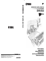
DVD RECEIVER / AMPLI-TUNER DVD
DVR-S150
OWNER’S MANUAL
MODE D’EMPLOI
BEDIENUNGSANLEITUNG
BRUKSANVISNING
ИНСТРУКЦИЯ ПО ЭКСПЛУАТАЦИИ
GEBRUIKSAANWIJZING
G
DVR-S150

i CAUTION
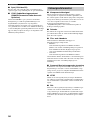
1 To assure the finest performance, please read this manual
carefully. Keep it in a safe place for future reference.
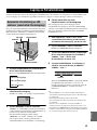
2 Install this sound system in a well ventilated, cool, dry, clean
place with at least 10 cm on the top, 10 cm on the left and right,
and 10 cm at the back of DVR-S150 — away from direct
sunlight, heat sources, vibration, dust, moisture, and/or cold.
3 Locate this unit away from other electrical appliances, motors, or
transformers to avoid humming sounds.
4 Do not expose this unit to sudden temperature changes from cold
to hot, and do not locate this unit in an environment with high
humidity (i.e. a room with a humidifier) to prevent condensation
inside this unit, which may cause an electrical shock, fire,
damage to this unit, and/or personal injury.
5 Avoid installing this unit where foreign object may fall onto this
unit and/or this unit may be exposed to liquid dripping or
splashing. On the top of this unit, do not place:
– Other components, as they may cause damage and/or
discoloration on the surface of this unit.
– Burning objects (i.e. candles), as they may cause fire, damage
to this unit, and/or personal injury.
– Containers with liquid in them, as they may fall and liquid
may cause electrical shock to the user and/or damage to this
unit.
6 Do not cover this unit with a newspaper, tablecloth, curtain, etc.
in order not to obstruct heat radiation. If the temperature inside
this unit rises, it may cause fire, damage to this unit, and/or
personal injury.
7 Do not plug in this unit to a wall outlet until all connections are
complete.
8 Do not operate this unit upside-down. It may overheat, possibly
causing damage.
9 Do not use force on switches, knobs and/or cords.
10 When disconnecting the power cable from the wall outlet, grasp
the plug; do not pull the cable.
11 Do not clean this unit with chemical solvents; this might damage
the finish. Use a clean, dry cloth.
12 Only voltage specified on this unit must be used. Using this unit
with a higher voltage than specified is dangerous and may cause
fire, damage to this unit, and/or personal injury. YAMAHA will
not be held responsible for any damage resulting from use of this
unit with a voltage other than specified.
13 To prevent damage by lightning, disconnect the power cable from
the wall outlet during an electrical storm.
14 Do not attempt to modify or fix this unit. Contact qualified
YAMAHA service personnel when any service is needed.
The cabinet should never be opened for any reasons.
15 When not planning to use this unit for long periods of time (i.e.
vacation), disconnect the AC power plug from the wall outlet.
16 Be sure to read the “Troubleshooting” section on common
operating errors before concluding that this unit is faulty.
17 Before moving this unit, press STANDBY/ON to set this unit in
standby mode, and disconnect the AC power plug from the wall
outlet.
18 Condensation will form when the surrounding temperature
changes suddenly. Disconnect the power cable from the outlet,
then leave the unit alone.
19 When using the unit for a long time, the unit may become warm.
Turn the power off, then leave the unit alone for cooling.
DANGER
When this unit is plugged to the wall outlet, do not place your
eyes close to the opening of the disc tray and other openings to
look into inside.
■ For U.K. customers
If the socket outlets in the home are not suitable for the plug
supplied with this appliance, it should be cut off and an
appropriate 3 pin plug fitted. For details, refer to the instructions
described below.
The plug severed from the mains lead must be destroyed, as a
plug with bared flexible cord is hazardous if engaged in a live
socket outlet.
■ Special Instructions for U.K. Model
CAUTION: READ THIS BEFORE OPERATING YOUR UNIT.
This unit is not disconnected from the AC power source as
long as it is connected to the wall outlet, even if this unit itself
is turned off. This state is called the standby mode. In this
state, this unit is designed to consume a very small quantity of
power.
FOR CANADIAN CUSTOMERS
To prevent electric shock, match wide blade of plug to wide
slot and fully insert.
This Class B digital apparatus complies with Canadian
ICES-003.
The laser component in this product is capable of emitting
radiation exceeding the limit for Class 1.
WARNING
TO REDUCE THE RISK OF FIRE OR ELECTRIC SHOCK,
DO NOT EXPOSE THIS APPLIANCE TO RAIN OR
MOISTURE.
Note
IMPORTANT
THE WIRES IN MAINS LEAD ARE COLOURED IN
ACCORDANCE WITH THE FOLLOWING CODE:
Blue: NEUTRAL
Brown: LIVE
As the colours of the wires in the mains lead of this appa-
ratus may not correspond with the coloured markings
identifying the terminals in your plug, proceed as follows:
The wire which is coloured BLUE must be connected to
the terminal which is marked with the letter N or coloured
BLACK. The wire which is coloured BROWN must be
connected to the terminal which is marked with the letter L
or coloured RED.
Making sure that neither core is connected to the earth
terminal of the three pin plug.

ii CAUTION
CAUTION: READ THIS BEFORE OPERATING YOUR UNIT.
English
CAUTION
Use of controls or adjustments or performance of procedures
other than those specified herein may result in hazardous
radiation exposure.
¶ The name plate is located on the bottom of the unit.

1
CONTENTS
English
Introduction ............................................................ 3
About this manual...................................................... 3
Supplied Accessories .............................................. 3
Controls and Functions.......................................... 4
Top and front panels .................................................. 4
Display....................................................................... 5
Remote control........................................................... 6
Connecting Speakers .............................................. 9
Connecting speakers
(Front/Surround/Center)...................................... 10
Connecting a subwoofer .......................................... 10
Using commercially available speakers or cables ... 11
Connecting a TV ................................................... 12
Connecting Antennas ........................................... 13
Connecting the FM antenna..................................... 13
Connecting the AM loop antenna ............................ 13
Connecting External AV Components ............... 14
Connecting a VCR................................................... 15
Connecting a game console ..................................... 16
Connecting a CD recorder or MD recorder ............. 17
Connecting the Power Cables.................................. 17
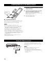
Installing Batteries in the Remote Control ........ 18
Using the Remote Control.................................... 18
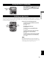
Turning the Power to On/Standby...................... 19
Selecting an Input Source .................................... 19
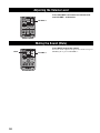
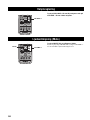
Adjusting the Volume Level ................................ 20
Muting the Sound (Mute) .................................... 20
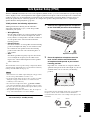
Auto Speaker Setup (YPAO)............................... 21
Enjoying Sound Field Programs
(DSP Programs) ................................................ 26
Setting the Sleep Timer ........................................ 28
Changing DVD Settings on the TV
(On-Screen Menu) ............................................ 29
Operating the On-Screen Menu............................... 29
On-Screen Menu guide............................................ 30
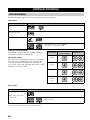
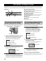
Supported Disc Types ...........................................32
Basic Playback Operations...................................33
Useful Playback Operations.................................34
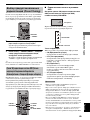
Specifying an elapsed time for playback (Time
Search)................................................................. 34
Customizing playback order (Program Play) .......... 35
Repeating playback (Repeat Play)........................... 37
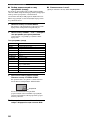
Operating disc menus (DVD menu/Video CD
Playback Control)................................................ 39
Selecting Audio and Subtitle Languages ............40
Selecting a Viewing Angle ...................................41
Zooming Images ...................................................42
Restricting Playback (Parental Control) ...........43
Setting the Parental Control level............................ 43
Locking discs ........................................................... 44
Playing locked discs ................................................ 44
Changing the password............................................ 45
Enjoying High-Quality Video
(NTSC/Progressive Scan) ................................46
Enjoying JPEG Images.........................................47
Tuning Radio Stations ..........................................48
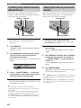
Tuning radio stations automatically
(Auto Tuning)...................................................... 48
Tuning radio stations manually (Manual Tuning)... 48
Selecting preset radio stations (Preset Tuning) ....... 49
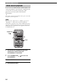
Receiving FM RDS stations
(U.K. and Europe models only)........................... 49
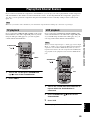
Presetting Radio Stations .....................................51
Presetting FM stations automatically
(Auto Preset)........................................................ 51
Presetting radio stations manually
(Manual Preset) ................................................... 52
Changing the order of preset radio stations ............. 52
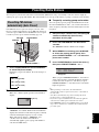
Playing Back External Sources............................53
TV playback ............................................................ 53
VCR playback.......................................................... 53
Game console playback ........................................... 54
Recording AV Sources With External AV
Components .......................................................55
Recording audio sources with CinemaStation......... 55
Copying video component sources to a video
cassette................................................................. 56
Contents
INTRODUCTION
PREPARATION
BASIC OPERATION
ENJOYING MOVIE AND MUSIC DISCS
ENJOYING RADIO
ENJOYING EXTERNAL AV SOURCES

2
Contents
Enjoying Sound with Specific Speakers..............57
Enjoying 6.1/5.1ch sources with all speakers
including a virtual speaker (Matrix 6.1).............. 57
Enjoying 2ch sources with all speakers
(Dolby Pro Logic II)............................................ 58
Enjoying DSP programs with the front speakers
only (Virtual CINEMA DSP).............................. 59
Enjoying DSP Programs in a Variety of
Ways...................................................................60
Listening with headphones
(“SILENT CINEMA”) ........................................ 60
Listening at low volume
(Night Listening)................................................. 61
Enjoying High-Quality Sound .............................62
Enjoying original Dolby and DTS sounds............... 62
Enjoying original 2ch sound (Stereo)...................... 63
Adjusting the Speaker Balance During
Playback.............................................................64
Adjusting the speaker balance with test tones......... 64
Adjusting the speaker balance during playback ...... 65
Configuring Dolby Pro Logic II Music
Settings...............................................................67
DSP Program Delay Time Settings .....................68
Configuring the Audio Input Signal Setting.......70
Checking the Audio Input Signal Type ................... 71
Controlling External Components ......................72
Setting remote control codes ................................... 72
Available operations................................................ 73
Configuring Various Parameters (Set Menu) ....75
Operating the Set Menu........................................... 76
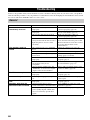
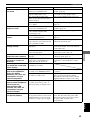
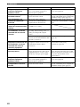
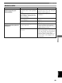
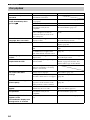
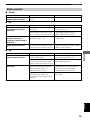
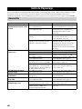
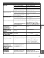
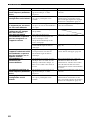
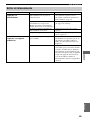
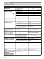
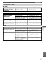
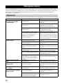
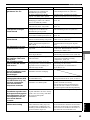
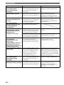
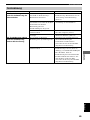
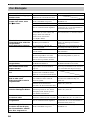
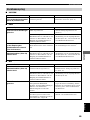
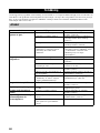
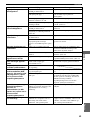
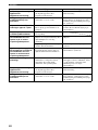
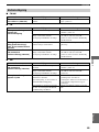
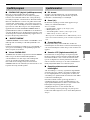
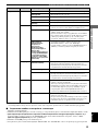
Troubleshooting ....................................................80
General..................................................................... 80
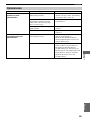
Remote control ........................................................ 83
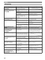
Disc playback .......................................................... 84
Radio reception........................................................ 85
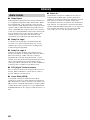
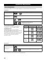
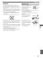
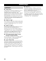
Additional Information ........................................86
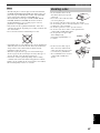
Disc Information...................................................... 86
Handling a disc ........................................................ 87
Glossary .................................................................88
Audio formats.......................................................... 88
Sound field programs............................................... 89
Audio information ................................................... 89
Video signal information......................................... 90
Copyright and logo marks ....................................... 91
Specifications.........................................................92
SOUND OPTIONS
ADVANCED CONFIGURATION
APPENDIX

3
INTRODUCTION
English
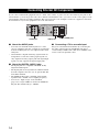
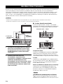
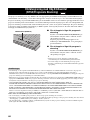
The YAMAHA CinemaStation “DVR-S150” is a slimline DVD receiver equipped with a digital amplifier. This product provides you
with the best sound possible, allowing you to enjoy not just DVDs and CDs, but various other AV sources as well. We hope the
“DVR-S150” brings you great listening pleasure and satisfaction.
• This manual provides information relevant only to the YAMAHA CinemaStation “DVR-S150”. For information on speakers or other
AV equipment, refer to the manual for that product.
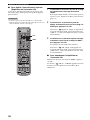
• In this manual, operations that can be performed using either the DVD receiver or its remote control are explained using the remote
control.
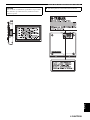
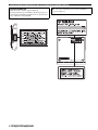
• Remote control descriptions and illustrations in this manual are based on the U.K. and Europe models unless otherwise specified.
• y indicates a tip for your operation.
• Notes contain important information about safety and operating instructions.
• This manual is printed prior to production. Design and specifications are subject to change in part as a result of improvements, etc. In
case of differences between the manual and the product, the product has priority.
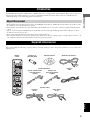
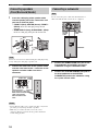
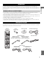
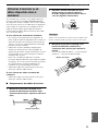
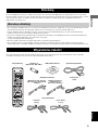
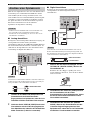
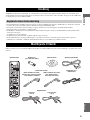
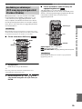
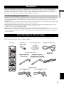
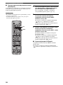
This product includes the following accessories. Before connecting speakers or a TV to this product, make sure you received all of the
following parts.
Introduction
About this manual
Supplied Accessories
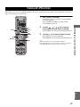
TV
CH
CINEMA
CH
STANDBY/ON
POWER
AUDIO
SELECT
NIGHT
SW
TV CH
TV INPUT
SLEEP
PRESET PRESET
A B C D E
CENTER
SURR
SHIFT
STEREOMATRIX 6.1
A-B
REPEAT
ANGLE
SUBTITLE
ON SCREEN
YPAO
MENU
TEST
RETURN
STATUS
ON/OFF
TV VOL
VOLUME
MUTE
AMP
DVD/CD
VCR
VIDEO
TUNER
MOVIE MUSIC SPORTS GAME
ENTER
START
PTY SEEK
MODE
SURROUND
SET MENU
START
FREQ/RDS
Indoor FM antenna
(U.S.A., Canada, China,
Asia and General
models)
(Europe, U.K.,
Australia and Korea
models)
Video pin
cable
Optimizer microphoneAM loop antennaBatteries (2)
(AA, R06, UM-3)
Remote
control
Speaker cables
Surround
15m (2)
Front, Center
5m (3)

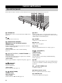
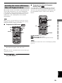
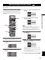
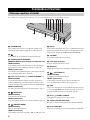
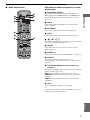
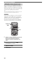
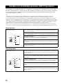
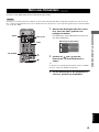
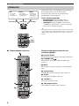
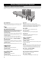
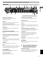
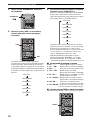
CONTROLS AND FUNCTIONS
4
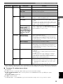
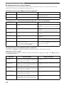
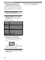
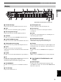
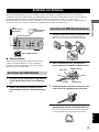
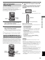
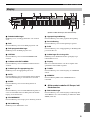
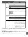
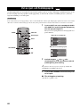
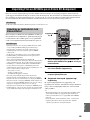
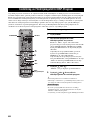
Buttons indicated with an asterisk (*) perform different functions depending on the selected mode of operation.
1 STANDBY/ON
Turn this unit on. Press to set the unit in the standby mode.
(page 19)
2
Opens and closes the disc tray.
3 PROGRESSIVE (MEMORY)
[MEMORY (for U.K. and Europe models)]
(DVD/CD mode)
Switches DVD playback between progressive scan and
interlace outputs. (page 46)
(Tuner mode)
Stores the current radio station for Preset Tuning.
(page 52)
4 b/w, f/a (d PRESET/TUNING u)
(DVD/CD mode)
Selects the previous/next track or chapter. Press and hold
to fast forward or fast reverse.
(Tuner mode)
Selects a preset number or adjusts the frequency. (page 51)
5 (A/B/C/D/E)
(DVD/CD mode)
Stops disc playback.
(Tuner mode)
Selects a preset group. (page 52)
6 (PRESET/BAND)
(DVD/CD mode)
Pauses disc playback.
(Tuner mode)
Switches between FM and AM. (page 48)
7 INPUT
Selects an input source or sets the priority level for the
audio input signals (if any equipment is connected to both
OPTICAL IN and AUDIO IN jacks).
8 VOLUME
Adjusts the overall volume level.
9 Disc tray
Holds a disc to be played.
0 Display
Displays playback information or settings. (page 5)
A (AUTO/MAN’L)
(DVD/CD mode)
Starts disc playback.
(Tuner mode)
Switches between Auto Tuning and Manual Tuning
modes. (page 48)
B DSP
Switches the DSP programs in the selected DSP program
group. Press and hold to switch the DSP program groups.
(page 26)
C SILENT CINEMA jack
Connects headphones.
D Remote control sensor
Receives signals from the remote control.
E YPAO MIC jack
Connects the optimizer microphone.
Controls and Functions
Top and front panels
12 3 4 56
7
8
E
D
C
B
A
0
9

5
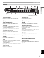
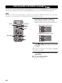
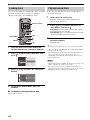
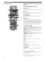
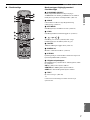
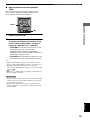
Controls and Functions
INTRODUCTION
English
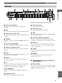
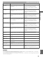
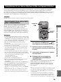
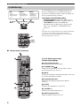
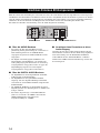
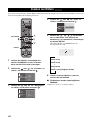
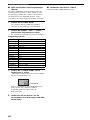
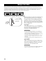
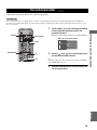
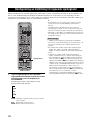
1 Decoder indicator
Displays the icon for the selected internal decoder.
2 DSP
Lights up when a DSP program is selected.
3 DSP program indicator
Displays the icon for the selected DSP program.
4 VIRTUAL
Lights up when Virtual CINEMA DSP is activated.
5 SILENT CINEMA indicator
Lights up when the Silent Cinema mode is activated.
6 Playback mode indicator
Displays the icon for the selected playback mode.
7 AUTO
Lights up when using the Auto Tuning or Auto Preset
mode.
8 SLEEP
Lights up when the Sleep Timer is on.
9 ST
Lights up when receiving a strong FM radio signal in the
Auto Tuning or Auto Preset mode.
0 PROGRESSIVE
Lights up when the progressive scan function is activated.
A Disc indicator
Displays the icon for the disc.
B Playback icon
Lights up during disc playback.
C Pause icon
Lights up when disc playback is paused.
D PCM
Lights up when playing PCM signals such as CDs.
E Display mode indicator
Displays the indicator for the information type shown in
the CinemaStation display.
F Display
Displays various information such as a title, chapter or
track number, or elapsed playing time.
G TUNED
Lights up when receiving an FM/AM broadcast.
H MEMORY
Blinks when presetting an FM/AM radio station.
■ U.K. and Europe models only
I RDS indicators
Light up when receiving an RDS signal. “PTY HOLD”
lights up when the PTY SEEK mode is activated.
(page 50)
Display
MATRIX
PCM
TITLE TRACK CHAP
VIRTUAL SILENT REP
A-B
ALL AUTO ST
MEMORY
TUNED
PROGRESSIVE
DIGITAL
DVD VCD
CD
PL DSP
PROG SLEEP
PS
PTY RT
PTY
CT
HOLD
2
4
56
7
E
C
B
A
9
0
1
D
3
8
F
I
G
H
(U.K. and Europe models only)

6
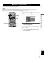
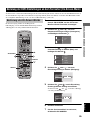
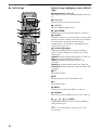
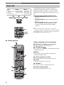
Controls and Functions
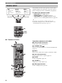
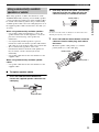
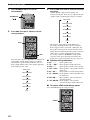
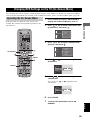
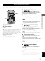
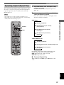
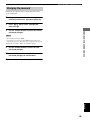
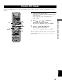
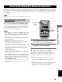
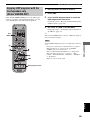
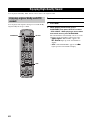
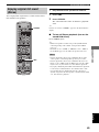
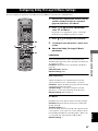
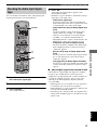
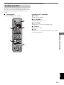
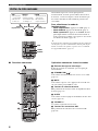
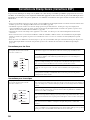
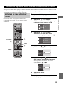
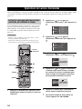
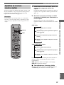
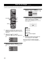
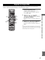
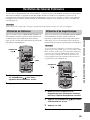
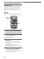
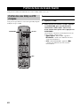
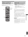
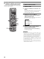
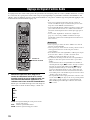
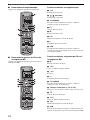
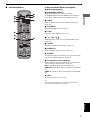
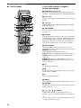
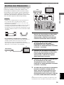
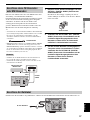
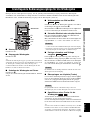
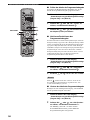
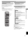
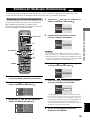
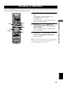
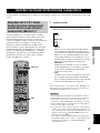
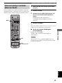
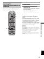
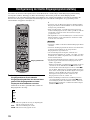
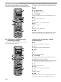
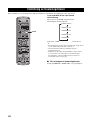
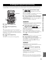
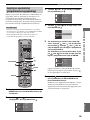
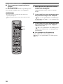
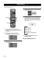
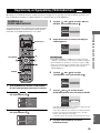
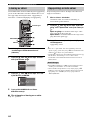
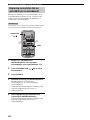
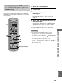
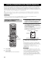
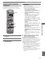
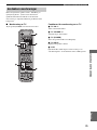
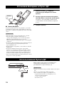
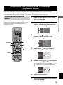
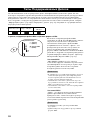
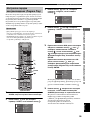
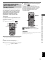
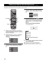
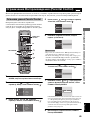
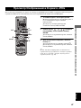
■ Common functions
CinemaStation has three main operation modes. Before
operating functions in each mode, you need to select a
mode to change the remote control button assignments.
To switch the operation mode
• Amp mode: Press AMP. (page 7)
• DVD/CD mode: Press DVD/CD. (page 8)
• Tuner mode: Press TUNER. For details on tuner
operations, refer to “Tuning Radio Stations” (page 48).
y
You can also operate the TV or VCR connected to the
CinemaStation using the remote control. For details, refer to
“Controlling External Components” (page 72).
Operations common to all modes
1 Infrared signal transmitter
Sends signals to the CinemaStation.
2 STANDBY/ON ( )
Turn the CinemaStation on, or set it to the standby mode.
(page 19)
3 MUTE
Turns off the volume. Press again to resume the volume.
4 Input selection buttons
Select an input source to operate. (page 19)
5 SLEEP
Sets the Sleep Timer. (page 28)
6 VOLUME +/–
Adjusts the overall volume level.
7 DSP program buttons
Selects a DSP program. (page 26)
Remote control
TV
POWER
POWER
AUDIO
SURROUND
SELECT
NIGHT
SW
CENTER
SURR
STEREOMATRIX 6.1
A-B
REPEAT
ANGLE
SUBTITLE
DVR-S120 WB56650
CINEMA
AMP
DVD/CD
VCR
VIDEO
TUNER
MOVIE MUSIC SPORTS GAME
AMP
• DSP program
selection
• Input selection,
etc.
DVD/CD
• Playback
• Subtitle and
audio language
selection, etc.
FM/AM
• Radio station
tuning
• Radio station
preset, etc.
Amp mode
DVD/CD mode
Tuner mode
AMP
TUNER
DVD/CD
TV
CH
CINEMA
CH
POWER
AUDIO
SURROUND
SELECT
NIGHT
SW
TV CH
TV INPUT
SLEEP
PRESET PRESET
A B C D E
CENTER
SURR
SHIFT
STEREOMATRIX 6.1
A-B
REPEAT
ANGLE
SUBTITLE
ON SCREEN MENU
TEST
RETURN
STATUS
TV VOL
VOLUME
MUTE
AMP
DVD/CD
VCR
VIDEO
TUNER
MOVIE MUSIC SPORTS GAME
SET MENU
ENTER
YPAO
ON/OFF
2
4
5
6
7
1
3
STANDBY/ON
START
PTY SEEK
MODE
START
FREQ/RDS

7
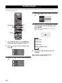
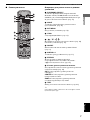
Controls and Functions
INTRODUCTION
English
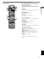
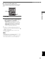
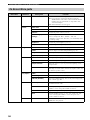
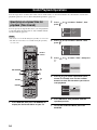
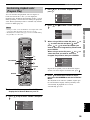
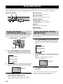
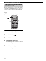
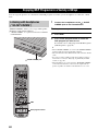
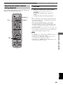
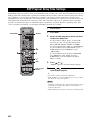
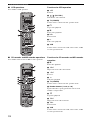
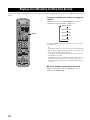
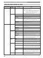
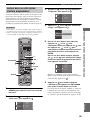
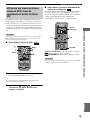
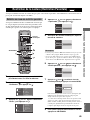
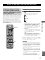
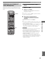
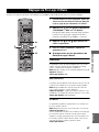
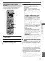
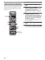
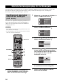
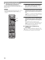
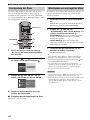
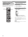
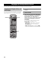
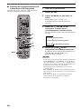
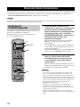
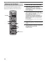
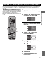
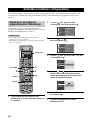
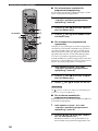
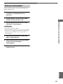
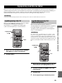
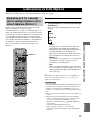
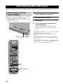
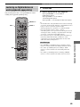
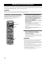
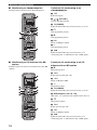
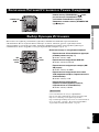
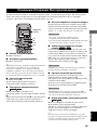
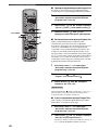
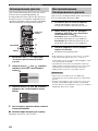
■ Amp mode Operations available only in amp mode
1 SURROUND, SELECT
Sets Dolby Digital or DTS. Press SURROUND and then
SELECT to set Dolby Pro Logic II for 2ch sources.
(page 58)
2 NIGHT
Sets the CinemaStation to the Night Listening mode.
(page 61)
3 SET MENU
Enters the Set Menu. (page 76)
4 YPAO
Starts the YPAO function. (page 21)
5 / / /
Adjusts the test tone (page 64) or Set Menu (page 76).
6 ON/OFF
Turns the YPAO mode on/off. (page 23)
7 MATRIX 6.1
Sets the Matrix 6.1 decoder. (page 57)
8 STEREO
Switches between normal stereo sound and audio with a
sound field effect. (page 63)
9 Speaker volume buttons
Adjusts the speaker balance (volume level of each
speaker). (page 65)
SW +/–: Adjusts the subwoofer volume.
CENTER +/–: Adjusts the center speaker volume.
SURR +/–: Adjusts the surround speaker volume.
0 TEST
Outputs a test tone. (page 64)
y
Amp mode operations are indicated in purple on the remote
control.
TV
CH
CINEMA
CH
POWER
AUDIO
SURROUND
SELECT
NIGHT
SW
TV CH
TV INPUT
SLEEP
PRESET PRESET
A B C D E
CENTER
SURR
SHIFT
STEREOMATRIX 6.1
A-B
REPEAT
ANGLE
SUBTITLE
ON SCREEN MENU
TEST
RETURN
STATUS
TV VOL
VOLUME
MUTE
AMP
DVD/CD
VCR
VIDEO
TUNER
MOVIE MUSIC SPORTS GAME
SET MENU
ENTER
YPAO
ON/OFF
2
3
5
8
7
9
0
1
STANDBY/ON
START
PTY SEEK
MODE
START
4
6
FREQ/RDS

8
Controls and Functions
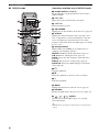
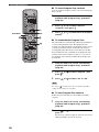
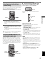
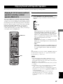
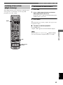
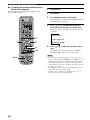
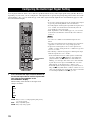
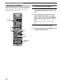
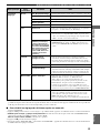
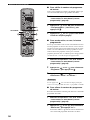
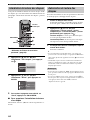
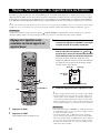
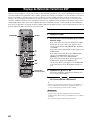
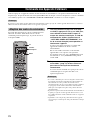
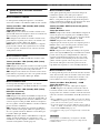
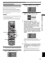
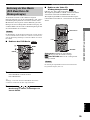
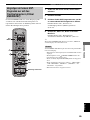
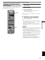
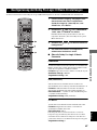
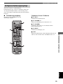
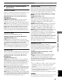
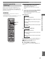
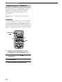
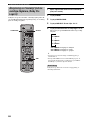
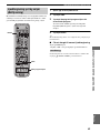
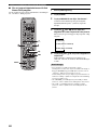
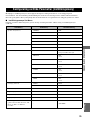
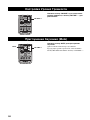
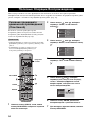
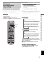
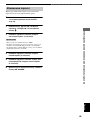
■ DVD/CD mode Operations available only in DVD/CD mode
1 Number buttons (1 to 9, 0)
Inputs numerals to specify parameters such as track or
chapter numbers.
2 b, a
Skips to the start of current track or next track.
3 w, f
Fast forwards/fast reverses.
4 ON SCREEN
Displays the On-Screen Menu on the TV screen. (page 29)
5 STATUS
Displays the status information such as disc type, total
time or elapsed time of current track/chapter on the TV
screen. To display the status information, the “Status
window” setting in the On-Screen Menu (page 29) should
be set to “On”.
6 Settings buttons
While holding down SHIFT, press a button below to
enable the corresponding operation.
REPEAT: Enables the Repeat Play mode. (page 37)
A-B: Enables the A-B Repeat mode. (page 38)
AUDIO: Selects the audio language of the DVD video.
(page 40)
ANGLE: Selects the disc viewing angle. (page 41)
SUBTITLE: Selects the subtitle language of the DVD
video. (page 40)
7 s
Stops disc playback.
8 e
Pauses disc playback or advances to the next frame.
9 h
Starts disc playback.
0 MENU
Displays the DVD menu on the TV screen. (page 39)
A RETURN
Returns the DVD menu to the previous screen. (page 39)
B / / / / ENTER
Operates the On-Screen Menu (page 29) or specify
various parameters.
y
DVD/CD mode operations are indicated in green on the remote
control.
TV
CH
CINEMA
CH
POWER
AUDIO
SURROUND
SELECT
NIGHT
SW
TV CH
TV INPUT
SLEEP
PRESET PRESET
A B C D E
CENTER
SURR
SHIFT
STEREOMATRIX 6.1
A-B
REPEAT
ANGLE
SUBTITLE
ON SCREEN MENU
TEST
RETURN
STATUS
TV VOL
VOLUME
MUTE
AMP
DVD/CD
VCR
VIDEO
TUNER
MOVIE MUSIC SPORTS GAME
SET MENU
ENTER
YPAO
ON/OFF
STANDBY/ON
START
PTY SEEK
MODE
FREQ/RDS
2
4
5
16
7
8
9
0
A
B
3
START

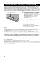
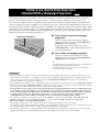
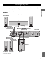
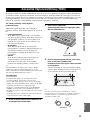
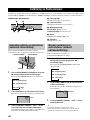
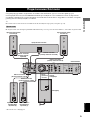
CONNECTING SPEAKERS
9
PREPARATION
English
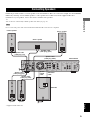
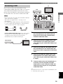
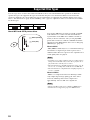
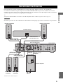
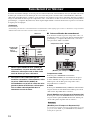
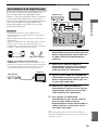
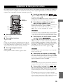
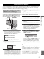
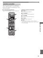
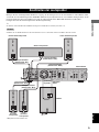
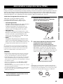
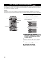
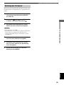
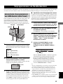
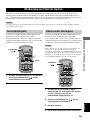
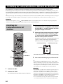
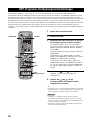
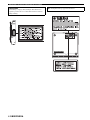
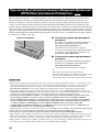
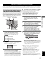
Follow the procedure below to connect speakers to the CinemaStation. Here, the connection example uses the YAMAHA
NX-P150 (consisting of four satellite speakers, a center speaker and a subwoofer) and its supplied cables. For
information on your speakers, refer to the owner’s manual for the speakers.
y
You can also use commercially available speakers and cables (see page 11).
Do not connect the power cable of the CinemaStation until all cable connections are completed.
* Supplied with the subwoofer.
Connecting Speakers
Note
DIGITAL
AUDIO
VIDEOS VIDEO
IN
VCR
OUT
AM
ANT
VCR
OUT
VCR
IN
VIDEO
IN
Y
P
B
PR
FM
ANT
GND
MONITOR
OUT
MONITOR
OUT
(DVD ONLY)
MONITOR
OUT
(DVD ONLY)
SUBWOOFER
SPEAKERS
CENTER FRONT
SURROUND
FRONT
SURROUND
OUT
VCR
IN
VIDEO
IN
COMPONENT
VIDEO
AUDIO
R
LR
L
SYSTEM
CONNECTOR
75 UNBAL
OUT
OPTICAL
SPEAKER IMPEDANCE: 6 MIN.
INPUT
SYSTEM
CONNECTOR
Front L speaker
Front R speaker
Center speaker
Surround L
speaker
Subwoofer
Surround R
speaker
CinemaStation
Speaker cable
(cable plug: green)
Speaker cable
(cable plug: red)
Speaker cable
(cable plug: white)
Speaker cable
(cable plug: gray)
Speaker cable
(cable plug: blue)
System
control
cable*
Subwoofer
cable*

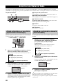
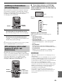
Connecting Speakers
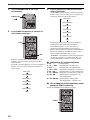
10
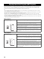
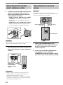
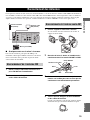
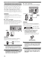
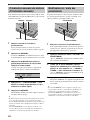
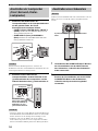
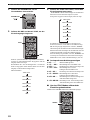
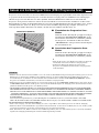
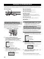
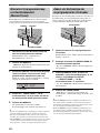
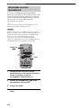
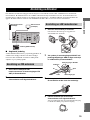
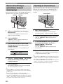
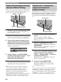
1 Insert the cable plug of the speaker cable
into the speaker jack of the same color until
you hear it click into place.
• FRONT R (Red), CENTER (Green), FRONT L
(White): Insert the cable plug facing the tub
upwards.
• SURROUND R (Gray), SURROUND L (Blue):
Insert the cable plug facing the tub downwards.
Do not use excessive force when inserting the cable plug. Doing
so may damage the cable plug or speaker jack.
2 Connect the cable core of the speaker cable
with the color band to the + connector on the
speaker and other cable core to the –
connector.
• Do not allow the cable cores to touch each other or any metal
part. Doing so may damage the unit or speakers.
• Make sure you connect the cable cores to the correct
connectors. Reversed connections may produce unnatural
sounds during playback.
Do not connect the power cable of the CinemaStation or
subwoofer until all cable connections are completed.
1 Connect the SUBWOOFER OUT jack on the
CinemaStation to the INPUT jack on the
subwoofer using the subwoofer cable.
2 Connect the SYSTEM CONNECTOR jack on
the CinemaStation to the SYSTEM
CONNECTOR jack on the subwoofer using
the system control cable.
Connecting speakers
(Front/Surround/Center)
Note
Notes
SPEAKERS
CENTER FRONT
SURROUND
FRONT
SURROUND
LR
SPEAKER IMPEDANCE: 6 MIN.
Tab
Red
Green
Tab
Gray
White
Blue
Cable core
Color
band
Lever
Press the lever
down, then insert the
cable core into the
hole and release the
lever.
Connecting a subwoofer
Note
VCR
OUT
VCR
IN
VIDEO
IN
SUBWOOFER
N
T
O
UND
OUT
AUDIO
RL
SYSTEM
CONNECTOR
7
MIN.
INPUT
SYSTEM
CONNECTOR
System
control
cable
Subwoofer
cable
Subwoofer

Connecting Speakers
11
PREPARATION
English
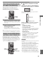
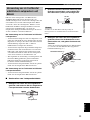
When using speakers or cables other than those of the
YAMAHA NX-P150 (consisting of four satellite speakers,
a center speaker and a subwoofer) and its supplied cables,
be careful of the following. When using a commercially
available speaker cable, remove the cable plug from one of
the supplied speaker cables and attach it to the cable you
are using.
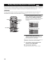
When using commercially available speakers
• Use speakers with 6-ohm impedance or more. If a
speaker with less than 6-ohm impedance is used, the
protective circuit may trip or the speaker may
malfunction.
• Use magnetically shielded speakers to prevent
interferences with a TV. If these speakers still interfere
with a TV, move the speakers a little away from the TV.
• We recommend using speakers of the same
manufacturer that have identical sound qualities. If
they are mixed, certain sounds may be heard
unnaturally.
• Use speaker cables that are the same thickness as the
supplied cables.
When using commercially available speaker
cables
• Use speaker cables that are the same thickness as the
supplied cables.
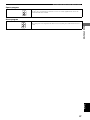
■ To replace speaker cables
1 Press and hold the release button and
remove the supplied speaker cable from the
cable plug.
2 Peel away about 10 mm (10/32”) of covering
from the tip of the new cable and twist the
cable core firmly in a clockwise direction.
Be sure to twist the cable core firmly in a clockwise direction.
Twisting loosely may cause a short.
3 Press and hold the release button, insert the
cable core into the cable plug, then release
the button.
Match the speaker cable polarity (+/–) with the
polarity mark (+/–) of the cable plug.
Using commercially available
speakers or cables
Release button
Note
10 mm (10/32”)
Clockwise
Polarity mark –
Polarity mark +

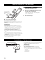
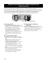
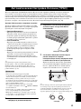
CONNECTING A TV
12
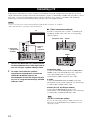
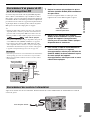
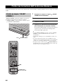
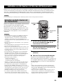
Follow the procedure below to connect your TV to CinemaStation using the supplied video pin cable. If you want to
output sound from the speakers connected to CinemaStation, prepare a commercially available audio pin cable to connect
them. Also, you can enjoy high-quality pictures with the component video, S-Video, or SCART (U.K. and Europe
models only) connection. For information about your TV, refer to the supplied manual.
• Do not connect the power cable of the CinemaStation until all cable connections are completed.
• Turn off the TV before connecting it to the CinemaStation.
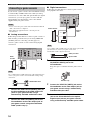
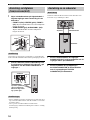
1 Connect the MONITOR OUT (VIDEO) jack on
the CinemaStation to the video input jack on
your TV using the supplied video pin cable.
2 To output sound from the speakers
connected to CinemaStation, connect the
VIDEO IN L/R (AUDIO) jacks on the
CinemaStation to the audio output L/R jacks
on your TV using the commercially available
audio pin cable.
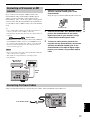
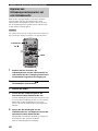
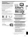
■ Other connection methods
To make a component video, S-Video, or SCART (U.K.
and Europe models only) connection, a corresponding
cable is required.
Component video
Connect the MONITOR OUT Y/P
B/PR (COMPONENT
VIDEO) jacks on the CinemaStation to the component
video input Y/P
B/PR jacks on your TV using a
commercially available component video cable.
S-Video
Connect the MONITOR OUT (S VIDEO) jack on the
CinemaStation to the S-Video input jack on your TV using
a commercially available S-Video cable.
SCART (for U.K. and Europe models)
Connect the AV MONITOR OUT jack on the
CinemaStation to the SCART input jack on your TV using
a commercially available SCART video cable.
(For U.K. and Europe models)
If you set the Video Output setting to “RGB” in the On-Screen
Menu (page 29), the MONITOR OUT (S VIDEO) jack cannot
output video signals.
Connecting a TV
Notes
DIGITAL
AUDI O
VIDEOS VIDEO
IN
VCR
OUT
AM
ANT
VCR
OUT
VCR
IN
VIDEO
IN
Y
P
B
P
R
FM
ANT
GND
MONITOR
OUT
MONITOR
OUT
(DVD ONLY)
MONITOR
OUT
(DVD ONLY)
SUBWOOFER
OUT
VCR
IN
VIDEO
IN
COMPONENT
VIDEO
AUDI O
RL
SYSTEM
CONNECTOR
75 UNBAL
OUT
OPTICAL
IN
OUT
VIDEO
AUDIO
L
R
TV
2 Audio cable
(commercially
available)
1 Video pin
cable
(supplied)
Note
DIGITAL
AUDI O
VIDEOS VIDEO
IN
VCR
OUT
AM
ANT
Y
P
B
PR
FM
ANT
GND
MONITOR
OUT
MONITOR
OUT
(DVD ONLY)
MONITOR
OUT
(DVD ONLY)
VCR
IN
VIDEO
IN
COMPONENT
VIDEO
75 UNBAL
OUT
OPTICAL
DIGITAL
AUDI O
VIDEO
IN
VCR
OUT
AM
ANT
Y
P
B
PR
FM
ANT
GND
MONITOR
OUT
MONITOR
OUT
(DVD ONLY)
MONITOR
OUT
(DVD ONLY)
VCR
IN
VIDEO
IN
COMPONENT
VIDEO
75 UNBAL
OUT
OPTICAL
S VIDEO
AV MONITOR OUT (DVD ONLY)
Component video S-Video
SCART
(U.K. and Europe models)

CONNECTING ANTENNAS
13
PREPARATION
English
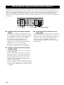
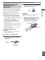
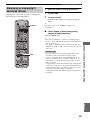
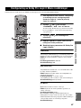
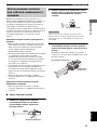
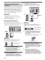
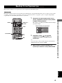
To enjoy radio on the CinemaStation, you need to connect AM and FM antennas to the CinemaStation. This product
includes an AM loop antenna and indoor FM antenna. If there is a problem of weak radio wave reception in your area or
you want to improve radio reception, we recommend that you use optional outdoor antennas. For details, consult the
nearest authorized YAMAHA dealer or service center.
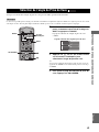
■ About grounding
For maximum safety and minimum interference, connect
the antenna GND terminal to a good earth ground. A good
earth ground is a metal stake driven into moist earth.
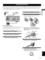
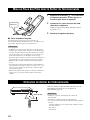
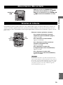
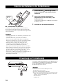
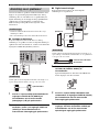
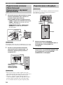
1 Connect the supplied indoor FM antenna to
the FM ANT jack on the CinemaStation.
2 Place the antenna away from the
CinemaStation and speaker cables.
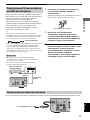
1 Attach the antenna stand to the antenna.
When attaching the antenna to the wall, you do not
need to use the antenna stand.
2 Open the lever to the right and insert the
antenna’s cord cores into the AM ANT and
GND terminals.
3 Close the lever and then pull the cord lightly
to make sure it is fastened properly.
4 Place the antenna away from the
CinemaStation and speaker cables.
While listening to the radio, rotate the antenna head
to find the best angle for reception.
Connecting Antennas
Connecting the FM antenna
DIGITAL
AUDIO
VIDEOS VIDEO
IN
VCR
OUT
AM
ANT
O
Y
P
B
PR
FM
ANT
GND
MONITOR
OUT
MONITOR
OUT
(DVD ONLY)
MONITOR
OUT
(DVD ONLY)
VCR
IN
VIDEO
IN
COMPONENT
VIDEO
75 UNBAL
OUT
OPTICAL
Indoor FM
antenna
(supplied)
AM loop
antenna
(supplied)
Ground (GND terminal)
Connecting the AM loop antenna
Cord Core
AM ANT terminal
Lever
GND terminal
Black
White

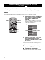
CONNECTING EXTERNAL AV COMPONENTS
14
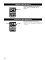
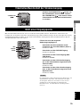
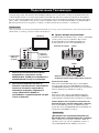
If you connect external AV equipment such as a VCR, video camera, or game console to the following AV jacks on the
CinemaStation, you can enjoy those AV sources with the CinemaStation. Also, you can record AV sources played on the
CinemaStation using the recording equipment. This section provides some examples of other AV equipment connections.
For information on your AV equipment, refer to the manual for it.
■ About the AUDIO jacks
• You cannot use both IN and OUT jacks for a same
category simultaneously. For example, the signal input
from the VCR IN jack does not output from the VCR
OUT jack.
• CinemaStation’s digital and analog signal circuits are
independent of each other. Analog input signals can
only output from analog output jacks and digital input
signals can only output from digital output jacks.
■ About the DIGITAL AUDIO jacks
• The digital jacks are compatible with PCM, Dolby
Digital and DTS signals.
• The digital jacks are designed based on EIA standards.
To make a digital connection, use an optical cable that
meets EIA standards.
• The OPTICAL IN jack is compatible with a digital
signal that has a 96 kHz or less sampling frequency.
• You can use “Input Assign” in the Set Menu
(page 78) to assign VIDEO or VCR to the OPTICAL
IN jack. The default setting is “VIDEO”.
■ Connecting a TV to an audio input
Enjoy TV sound with CinemaStation by connecting the
TV audio output jack to the AUDIO IN jack using a
commercially available audio cable. Press VIDEO on the
remote control to input TV sound.
Connecting External AV Components
DIGITAL
AUDIO
VIDEOS VIDEO
IN
VCR
OUT
AM
ANT
VCR
OUT
VCR
IN
VIDEO
IN
Y
P
B
PR
FM
ANT
GND
MONITOR
OUT
MONITOR
OUT
(DVD ONLY)
MONITOR
OUT
(DVD ONLY)
SUBWOOFER
OUT
VCR
IN
VIDEO
IN
COMPONENT
VIDEO
AUDIO
RL
SYSTEM
CONNECTOR
75 UNBAL
OUT
OPTICAL
AUDIO jacks
VIDEO jacks
DIGITAL AUDIO jacks

Connecting External AV Components
15
PREPARATION
English
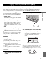
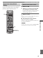
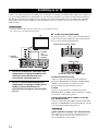
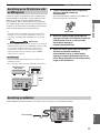
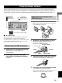
If you connect a VCR to the CinemaStation using
commercially available audio/video cables, you can enjoy
videos with the CinemaStation and record AV sources
played on the CinemaStation on the VCR. For information
on your VCR, refer to the owner’s manual for the VCR.
• Do not connect the power cable of the CinemaStation until all
cable connections are completed.
• Turn off the AV equipment before connecting it to the
CinemaStation.
• Use commercially available audio/video cables (shown below)
to connect a VCR to the CinemaStation or a TV. To make all
connections, three audio/video cables are required.
• For U.K. and Europe models only: Do not connect a TV to
CinemaStation via a VCR using SCART connections. The
copyright protection technology incorporated in the
CinemaStation may not allow the VCR to play.
1 Connect the VCR OUT L/R (AUDIO) jacks on
the CinemaStation to the audio input L/R
jacks on your VCR using a commercially
available audio/video cable.
2 Connect the VCR OUT (VIDEO) jack on the
CinemaStation to the video input jack on
your VCR using the audio/video cable (used
in step 1).
3 Connect the VIDEO IN L/R (AUDIO) jacks on
the CinemaStation to the audio output L/R
jacks on your VCR using another audio/video
cable.
4 Connect the VIDEO IN (VIDEO) jack on the
CinemaStation to the video output jack on
your VCR using the audio/video cable (used
in step 3).
5 To watch videos when the CinemaStation is
turned off, connect the audio and video
output jacks on your VCR to the audio and
video input jacks on your TV using another
audio/video cable.
y
For information on how to connect a TV to CinemaStation, refer
to “Connecting a TV” (page 12).
Connecting a VCR
Notes
Audio/Video cable SCART cable
CinemaStation
TV
DIGITAL
AUDIO
VIDEOS VIDEO
IN
VCR
OUT
AM
ANT
VCR
OUT
VCR
IN
VIDEO
IN
Y
P
B
PR
FM
ANT
GND
MONITOR
OUT
MONITOR
OUT
(DVD ONLY)
MONITOR
OUT
(DVD ONLY)
VCR
IN
VIDEO
IN
COMPONENT
VIDEO
AUDIO
RL
75 UNBAL
OUT
OPTICAL
L
R
L
R
AUDIO
VIDEO
L
R
L
R
AUDIO
VIDEO
AUDIO
VIDEO
IN OUT IN
VCR
TV
1
2
3
4
5

Connecting External AV Components
16
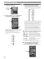
If you connect a game console to the CinemaStation using
a commercially available audio/video cable (for analog
connections) or a video cable and optical cable (for digital
connections), you can enjoy games or videos with the
CinemaStation. For information, refer to the manual
supplied with your game console.
• Do not connect the power cable of the CinemaStation until all
cable connections are completed.
• Turn off the AV equipment before connecting it to the
CinemaStation.
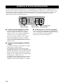
■ Analog connections
Follow the procedure below to connect a game console or
with an analog connection. If you are using VIDEO IN
(AUDIO) jacks for connecting your TV (page 12),
connect a game console or video camera using digital
connections.
Use a commercially available audio/video cable (shown below) to
connect your game console to the CinemaStation using analog
connections.
1 Connect the VIDEO IN L/R (AUDIO) jacks on
the CinemaStation to the audio output L/R
jacks on your game console using a
commercially available audio/video cable.
2 Connect the VIDEO IN (VIDEO) jack on the
CinemaStation to the video output jack on
your game console using the audio/video
cable (used in step 1).
■ Digital connections
Follow the procedure below to connect a game console
using digital connections.
Use a commercially available video pin cable and an optical cable
(shown below) to connect your game console to the
CinemaStation with a digital connection.
1 Remove the anti-dust cap from the OPTICAL
IN (DIGITAL AUDIO) jack on the
CinemaStation.
Keep the cap to re-attach it when the jack is not in
use.
2 Connect the VIDEO IN (VIDEO) jack on the
CinemaStation to the video output jack on
your game console using a commercially
available video pin cable.
3 Connect the OPTICAL IN (DIGITAL AUDIO)
jack on the CinemaStation to the optical
digital output jack on your game console
using a commercially available optical cable.
Connecting a game console
Notes
Note
VIDEOS VIDEO
VCR
OUT
AM
ANT
VCR
OUT
VCR
IN
VIDEO
IN
Y
P
B
PR
FM
ANT
GND
MONITOR
OUT
MONITOR
OUT
(DVD ONLY)
MONITOR
OUT
(DVD ONLY)
VCR
IN
VIDEO
IN
COMPONENT
VIDEO
AUDIO
RL
75 UNBAL
OUTPUT
L
R
AUDIO
VIDEO
Game
console
1
2
Audio/Video cable
Note
DIGITAL
AUDIO
VIDEO
S
VIDEO
IN
VCR
OUT
MONITOR
OUT
I
TOR
U
T
O
NLY)
VCR
IN
VIDEO
IN
OUT
OPTICAL
VIDEO
DIGITAL
OPTICAL
OUT
Video pin
cable
Optical
cable
Game console
Video pin cable
Optical cable
Anti-dust cap

Connecting External AV Components
17
PREPARATION
English
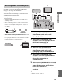
If you connect a CD recorder or MD recorder to the
CinemaStation using commercially available optical
cables, you can record audio sources played on the
CinemaStation. Also, you can enjoy audio sources played
on the recorder with the CinemaStation. For information
on your CD recorder or MD recorder, refer to the manual
for it.
y
• Use a commercially available optical cable (shown below) to
connect your CD recorder or MD recorder to the
CinemaStation. To make all connections, two optical cables are
required.
• AM/FM broadcasts cannot be output from this unit’s OPTICAL
OUT (DIGITAL AUDIO) jack. To record AM/FM broadcasts,
use a commercially available audio cable to connect the VCR
OUT jack on the CinemaStation to the analog input jack on
your recorder (see page 55).
• Do not connect the power cable of the CinemaStation until all
cable connections are completed.
• Turn off the AV component before connecting it to the
CinemaStation.
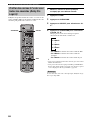
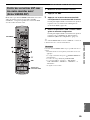
1 Remove the anti-dust caps from the
OPTICAL (DIGITAL AUDIO) jacks on the
CinemaStation.
Keep the cap to re-attach it when the jack is not in use.
2 Connect the OPTICAL OUT (DIGITAL AUDIO)
jack on the CinemaStation to the optical
digital input jack on your recorder using a
commercially available optical cable.
3 To listen to audio sources played on the
recorder with the CinemaStation, connect the
OPTICAL IN (DIGITAL AUDIO) jack on the
CinemaStation to the optical digital output
jack on your recorder using another optical
cable.
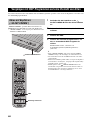
After you made all connections, connect the power cables of the CinemaStation and subwoofer.
Connecting a CD recorder or MD
recorder
Notes
Optical cable
DIGITAL
AUDIO
VIDEOS VIDEO
IN
VCR
OUT
MONITOR
OUT
MONITOR
OUT
(DVD ONLY)
VCR
IN
VIDEO
IN
OUT
OPTICAL
OUT
OPTICAL
IN
CD recorder or
MD recorder
Optical
cable
Optical
cable
Anti-dust cap
Connecting the Power Cables
SPEAKERS
CENTER FRONT
SURROUND
FRONT
SURROUND
LR
SPEAKER IMPEDANCE: 6 MIN.
To an AC wall outlet
Sayfa yükleniyor...
Sayfa yükleniyor...
Sayfa yükleniyor...
Sayfa yükleniyor...
Sayfa yükleniyor...
Sayfa yükleniyor...
Sayfa yükleniyor...
Sayfa yükleniyor...
Sayfa yükleniyor...
Sayfa yükleniyor...
Sayfa yükleniyor...
Sayfa yükleniyor...
Sayfa yükleniyor...
Sayfa yükleniyor...
Sayfa yükleniyor...
Sayfa yükleniyor...
Sayfa yükleniyor...
Sayfa yükleniyor...
Sayfa yükleniyor...
Sayfa yükleniyor...
Sayfa yükleniyor...
Sayfa yükleniyor...
Sayfa yükleniyor...
Sayfa yükleniyor...
Sayfa yükleniyor...
Sayfa yükleniyor...
Sayfa yükleniyor...
Sayfa yükleniyor...
Sayfa yükleniyor...
Sayfa yükleniyor...
Sayfa yükleniyor...
Sayfa yükleniyor...
Sayfa yükleniyor...
Sayfa yükleniyor...
Sayfa yükleniyor...
Sayfa yükleniyor...
Sayfa yükleniyor...
Sayfa yükleniyor...
Sayfa yükleniyor...
Sayfa yükleniyor...
Sayfa yükleniyor...
Sayfa yükleniyor...
Sayfa yükleniyor...
Sayfa yükleniyor...
Sayfa yükleniyor...
Sayfa yükleniyor...
Sayfa yükleniyor...
Sayfa yükleniyor...
Sayfa yükleniyor...
Sayfa yükleniyor...
Sayfa yükleniyor...
Sayfa yükleniyor...
Sayfa yükleniyor...
Sayfa yükleniyor...
Sayfa yükleniyor...
Sayfa yükleniyor...
Sayfa yükleniyor...
Sayfa yükleniyor...
Sayfa yükleniyor...
Sayfa yükleniyor...
Sayfa yükleniyor...
Sayfa yükleniyor...
Sayfa yükleniyor...
Sayfa yükleniyor...
Sayfa yükleniyor...
Sayfa yükleniyor...
Sayfa yükleniyor...
Sayfa yükleniyor...
Sayfa yükleniyor...
Sayfa yükleniyor...
Sayfa yükleniyor...
Sayfa yükleniyor...
Sayfa yükleniyor...
Sayfa yükleniyor...
Sayfa yükleniyor...
Sayfa yükleniyor...
Sayfa yükleniyor...
Sayfa yükleniyor...
Sayfa yükleniyor...
Sayfa yükleniyor...
Sayfa yükleniyor...
Sayfa yükleniyor...
Sayfa yükleniyor...
Sayfa yükleniyor...
Sayfa yükleniyor...
Sayfa yükleniyor...
Sayfa yükleniyor...
Sayfa yükleniyor...
Sayfa yükleniyor...
Sayfa yükleniyor...
Sayfa yükleniyor...
Sayfa yükleniyor...
Sayfa yükleniyor...
Sayfa yükleniyor...
Sayfa yükleniyor...
Sayfa yükleniyor...
Sayfa yükleniyor...
Sayfa yükleniyor...
Sayfa yükleniyor...
Sayfa yükleniyor...
Sayfa yükleniyor...
Sayfa yükleniyor...
Sayfa yükleniyor...
Sayfa yükleniyor...
Sayfa yükleniyor...
Sayfa yükleniyor...
Sayfa yükleniyor...
Sayfa yükleniyor...
Sayfa yükleniyor...
Sayfa yükleniyor...
Sayfa yükleniyor...
Sayfa yükleniyor...
Sayfa yükleniyor...
Sayfa yükleniyor...
Sayfa yükleniyor...
Sayfa yükleniyor...
Sayfa yükleniyor...
Sayfa yükleniyor...
Sayfa yükleniyor...
Sayfa yükleniyor...
Sayfa yükleniyor...
Sayfa yükleniyor...
Sayfa yükleniyor...
Sayfa yükleniyor...
Sayfa yükleniyor...
Sayfa yükleniyor...
Sayfa yükleniyor...
Sayfa yükleniyor...
Sayfa yükleniyor...
Sayfa yükleniyor...
Sayfa yükleniyor...
Sayfa yükleniyor...
Sayfa yükleniyor...
Sayfa yükleniyor...
Sayfa yükleniyor...
Sayfa yükleniyor...
Sayfa yükleniyor...
Sayfa yükleniyor...
Sayfa yükleniyor...
Sayfa yükleniyor...
Sayfa yükleniyor...
Sayfa yükleniyor...
Sayfa yükleniyor...
Sayfa yükleniyor...
Sayfa yükleniyor...
Sayfa yükleniyor...
Sayfa yükleniyor...
Sayfa yükleniyor...
Sayfa yükleniyor...
Sayfa yükleniyor...
Sayfa yükleniyor...
Sayfa yükleniyor...
Sayfa yükleniyor...
Sayfa yükleniyor...
Sayfa yükleniyor...
Sayfa yükleniyor...
Sayfa yükleniyor...
Sayfa yükleniyor...
Sayfa yükleniyor...
Sayfa yükleniyor...
Sayfa yükleniyor...
Sayfa yükleniyor...
Sayfa yükleniyor...
Sayfa yükleniyor...
Sayfa yükleniyor...
Sayfa yükleniyor...
Sayfa yükleniyor...
Sayfa yükleniyor...
Sayfa yükleniyor...
Sayfa yükleniyor...
Sayfa yükleniyor...
Sayfa yükleniyor...
Sayfa yükleniyor...
Sayfa yükleniyor...
Sayfa yükleniyor...
Sayfa yükleniyor...
Sayfa yükleniyor...
Sayfa yükleniyor...
Sayfa yükleniyor...
Sayfa yükleniyor...
Sayfa yükleniyor...
Sayfa yükleniyor...
Sayfa yükleniyor...
Sayfa yükleniyor...
Sayfa yükleniyor...
Sayfa yükleniyor...
Sayfa yükleniyor...
Sayfa yükleniyor...
Sayfa yükleniyor...
Sayfa yükleniyor...
Sayfa yükleniyor...
Sayfa yükleniyor...
Sayfa yükleniyor...
Sayfa yükleniyor...
Sayfa yükleniyor...
Sayfa yükleniyor...
Sayfa yükleniyor...
Sayfa yükleniyor...
Sayfa yükleniyor...
Sayfa yükleniyor...
Sayfa yükleniyor...
Sayfa yükleniyor...
Sayfa yükleniyor...
Sayfa yükleniyor...
Sayfa yükleniyor...
Sayfa yükleniyor...
Sayfa yükleniyor...
Sayfa yükleniyor...
Sayfa yükleniyor...
Sayfa yükleniyor...
Sayfa yükleniyor...
Sayfa yükleniyor...
Sayfa yükleniyor...
Sayfa yükleniyor...
Sayfa yükleniyor...
Sayfa yükleniyor...
Sayfa yükleniyor...
Sayfa yükleniyor...
Sayfa yükleniyor...
Sayfa yükleniyor...
Sayfa yükleniyor...
Sayfa yükleniyor...
Sayfa yükleniyor...
Sayfa yükleniyor...
Sayfa yükleniyor...
Sayfa yükleniyor...
Sayfa yükleniyor...
Sayfa yükleniyor...
Sayfa yükleniyor...
Sayfa yükleniyor...
Sayfa yükleniyor...
Sayfa yükleniyor...
Sayfa yükleniyor...
Sayfa yükleniyor...
Sayfa yükleniyor...
Sayfa yükleniyor...
Sayfa yükleniyor...
Sayfa yükleniyor...
Sayfa yükleniyor...
Sayfa yükleniyor...
Sayfa yükleniyor...
Sayfa yükleniyor...
Sayfa yükleniyor...
Sayfa yükleniyor...
Sayfa yükleniyor...
Sayfa yükleniyor...
Sayfa yükleniyor...
Sayfa yükleniyor...
Sayfa yükleniyor...
Sayfa yükleniyor...
Sayfa yükleniyor...
Sayfa yükleniyor...
Sayfa yükleniyor...
Sayfa yükleniyor...
Sayfa yükleniyor...
Sayfa yükleniyor...
Sayfa yükleniyor...
Sayfa yükleniyor...
Sayfa yükleniyor...
Sayfa yükleniyor...
Sayfa yükleniyor...
Sayfa yükleniyor...
Sayfa yükleniyor...
Sayfa yükleniyor...
Sayfa yükleniyor...
Sayfa yükleniyor...
Sayfa yükleniyor...
Sayfa yükleniyor...
Sayfa yükleniyor...
Sayfa yükleniyor...
Sayfa yükleniyor...
Sayfa yükleniyor...
Sayfa yükleniyor...
Sayfa yükleniyor...
Sayfa yükleniyor...
Sayfa yükleniyor...
Sayfa yükleniyor...
Sayfa yükleniyor...
Sayfa yükleniyor...
Sayfa yükleniyor...
Sayfa yükleniyor...
Sayfa yükleniyor...
Sayfa yükleniyor...
Sayfa yükleniyor...
Sayfa yükleniyor...
Sayfa yükleniyor...
Sayfa yükleniyor...
Sayfa yükleniyor...
Sayfa yükleniyor...
Sayfa yükleniyor...
Sayfa yükleniyor...
Sayfa yükleniyor...
Sayfa yükleniyor...
Sayfa yükleniyor...
Sayfa yükleniyor...
Sayfa yükleniyor...
Sayfa yükleniyor...
Sayfa yükleniyor...
Sayfa yükleniyor...
Sayfa yükleniyor...
Sayfa yükleniyor...
Sayfa yükleniyor...
Sayfa yükleniyor...
Sayfa yükleniyor...
Sayfa yükleniyor...
Sayfa yükleniyor...
Sayfa yükleniyor...
Sayfa yükleniyor...
Sayfa yükleniyor...
Sayfa yükleniyor...
Sayfa yükleniyor...
Sayfa yükleniyor...
Sayfa yükleniyor...
Sayfa yükleniyor...
Sayfa yükleniyor...
Sayfa yükleniyor...
Sayfa yükleniyor...
Sayfa yükleniyor...
Sayfa yükleniyor...
Sayfa yükleniyor...
Sayfa yükleniyor...
Sayfa yükleniyor...
Sayfa yükleniyor...
Sayfa yükleniyor...
Sayfa yükleniyor...
Sayfa yükleniyor...
Sayfa yükleniyor...
Sayfa yükleniyor...
Sayfa yükleniyor...
Sayfa yükleniyor...
Sayfa yükleniyor...
Sayfa yükleniyor...
Sayfa yükleniyor...
Sayfa yükleniyor...
Sayfa yükleniyor...
Sayfa yükleniyor...
Sayfa yükleniyor...
Sayfa yükleniyor...
Sayfa yükleniyor...
Sayfa yükleniyor...
Sayfa yükleniyor...
Sayfa yükleniyor...
Sayfa yükleniyor...
Sayfa yükleniyor...
Sayfa yükleniyor...
Sayfa yükleniyor...
Sayfa yükleniyor...
Sayfa yükleniyor...
Sayfa yükleniyor...
Sayfa yükleniyor...
Sayfa yükleniyor...
Sayfa yükleniyor...
Sayfa yükleniyor...
Sayfa yükleniyor...
Sayfa yükleniyor...
Sayfa yükleniyor...
Sayfa yükleniyor...
Sayfa yükleniyor...
Sayfa yükleniyor...
Sayfa yükleniyor...
Sayfa yükleniyor...
Sayfa yükleniyor...
Sayfa yükleniyor...
Sayfa yükleniyor...
Sayfa yükleniyor...
Sayfa yükleniyor...
Sayfa yükleniyor...
Sayfa yükleniyor...
Sayfa yükleniyor...
Sayfa yükleniyor...
Sayfa yükleniyor...
Sayfa yükleniyor...
Sayfa yükleniyor...
Sayfa yükleniyor...
Sayfa yükleniyor...
Sayfa yükleniyor...
Sayfa yükleniyor...
Sayfa yükleniyor...
Sayfa yükleniyor...
Sayfa yükleniyor...
Sayfa yükleniyor...
Sayfa yükleniyor...
Sayfa yükleniyor...
Sayfa yükleniyor...
Sayfa yükleniyor...
Sayfa yükleniyor...
Sayfa yükleniyor...
Sayfa yükleniyor...
Sayfa yükleniyor...
Sayfa yükleniyor...
Sayfa yükleniyor...
Sayfa yükleniyor...
Sayfa yükleniyor...
Sayfa yükleniyor...
Sayfa yükleniyor...
Sayfa yükleniyor...
Sayfa yükleniyor...
Sayfa yükleniyor...
Sayfa yükleniyor...
Sayfa yükleniyor...
Sayfa yükleniyor...
Sayfa yükleniyor...
Sayfa yükleniyor...
Sayfa yükleniyor...
Sayfa yükleniyor...
Sayfa yükleniyor...
Sayfa yükleniyor...
Sayfa yükleniyor...
Sayfa yükleniyor...
Sayfa yükleniyor...
Sayfa yükleniyor...
Sayfa yükleniyor...
Sayfa yükleniyor...
Sayfa yükleniyor...
Sayfa yükleniyor...
Sayfa yükleniyor...
Sayfa yükleniyor...
Sayfa yükleniyor...
Sayfa yükleniyor...
Sayfa yükleniyor...
Sayfa yükleniyor...
Sayfa yükleniyor...
Sayfa yükleniyor...
Sayfa yükleniyor...
Sayfa yükleniyor...
Sayfa yükleniyor...
Sayfa yükleniyor...
Sayfa yükleniyor...
Sayfa yükleniyor...
Sayfa yükleniyor...
Sayfa yükleniyor...
Sayfa yükleniyor...
Sayfa yükleniyor...
Sayfa yükleniyor...
Sayfa yükleniyor...
Sayfa yükleniyor...
Sayfa yükleniyor...
Sayfa yükleniyor...
Sayfa yükleniyor...
Sayfa yükleniyor...
Sayfa yükleniyor...
Sayfa yükleniyor...
Sayfa yükleniyor...
Sayfa yükleniyor...
Sayfa yükleniyor...
Sayfa yükleniyor...
Sayfa yükleniyor...
Sayfa yükleniyor...
Sayfa yükleniyor...
Sayfa yükleniyor...
Sayfa yükleniyor...
Sayfa yükleniyor...
Sayfa yükleniyor...
Sayfa yükleniyor...
Sayfa yükleniyor...
Sayfa yükleniyor...
Sayfa yükleniyor...
Sayfa yükleniyor...
Sayfa yükleniyor...
Sayfa yükleniyor...
Sayfa yükleniyor...
Sayfa yükleniyor...
Sayfa yükleniyor...
Sayfa yükleniyor...
Sayfa yükleniyor...
Sayfa yükleniyor...
Sayfa yükleniyor...
Sayfa yükleniyor...
Sayfa yükleniyor...
Sayfa yükleniyor...
Sayfa yükleniyor...
Sayfa yükleniyor...
Sayfa yükleniyor...
Sayfa yükleniyor...
Sayfa yükleniyor...
Sayfa yükleniyor...
Sayfa yükleniyor...
Sayfa yükleniyor...
Sayfa yükleniyor...
Sayfa yükleniyor...
Sayfa yükleniyor...
Sayfa yükleniyor...
Sayfa yükleniyor...
Sayfa yükleniyor...
Sayfa yükleniyor...
Sayfa yükleniyor...
Sayfa yükleniyor...
Sayfa yükleniyor...
Sayfa yükleniyor...
Sayfa yükleniyor...
Sayfa yükleniyor...
Sayfa yükleniyor...
Sayfa yükleniyor...
Sayfa yükleniyor...
Sayfa yükleniyor...
Sayfa yükleniyor...
Sayfa yükleniyor...
Sayfa yükleniyor...
Sayfa yükleniyor...
Sayfa yükleniyor...
Sayfa yükleniyor...
Sayfa yükleniyor...
Sayfa yükleniyor...
Sayfa yükleniyor...
Sayfa yükleniyor...
Sayfa yükleniyor...
Sayfa yükleniyor...
Sayfa yükleniyor...
Sayfa yükleniyor...
Sayfa yükleniyor...
Sayfa yükleniyor...
Sayfa yükleniyor...
Sayfa yükleniyor...
Sayfa yükleniyor...
Sayfa yükleniyor...
Sayfa yükleniyor...
Sayfa yükleniyor...
Sayfa yükleniyor...
Sayfa yükleniyor...
Sayfa yükleniyor...
Sayfa yükleniyor...
Sayfa yükleniyor...
Sayfa yükleniyor...
Sayfa yükleniyor...
Sayfa yükleniyor...
Sayfa yükleniyor...
Sayfa yükleniyor...
Sayfa yükleniyor...
Sayfa yükleniyor...
Sayfa yükleniyor...
Sayfa yükleniyor...
Sayfa yükleniyor...
Sayfa yükleniyor...
Sayfa yükleniyor...
Sayfa yükleniyor...
Sayfa yükleniyor...
Sayfa yükleniyor...
Sayfa yükleniyor...
Sayfa yükleniyor...
Sayfa yükleniyor...
Sayfa yükleniyor...
Sayfa yükleniyor...
Sayfa yükleniyor...
Sayfa yükleniyor...
Sayfa yükleniyor...
Sayfa yükleniyor...
Sayfa yükleniyor...
-
 1
1
-
 2
2
-
 3
3
-
 4
4
-
 5
5
-
 6
6
-
 7
7
-
 8
8
-
 9
9
-
 10
10
-
 11
11
-
 12
12
-
 13
13
-
 14
14
-
 15
15
-
 16
16
-
 17
17
-
 18
18
-
 19
19
-
 20
20
-
 21
21
-
 22
22
-
 23
23
-
 24
24
-
 25
25
-
 26
26
-
 27
27
-
 28
28
-
 29
29
-
 30
30
-
 31
31
-
 32
32
-
 33
33
-
 34
34
-
 35
35
-
 36
36
-
 37
37
-
 38
38
-
 39
39
-
 40
40
-
 41
41
-
 42
42
-
 43
43
-
 44
44
-
 45
45
-
 46
46
-
 47
47
-
 48
48
-
 49
49
-
 50
50
-
 51
51
-
 52
52
-
 53
53
-
 54
54
-
 55
55
-
 56
56
-
 57
57
-
 58
58
-
 59
59
-
 60
60
-
 61
61
-
 62
62
-
 63
63
-
 64
64
-
 65
65
-
 66
66
-
 67
67
-
 68
68
-
 69
69
-
 70
70
-
 71
71
-
 72
72
-
 73
73
-
 74
74
-
 75
75
-
 76
76
-
 77
77
-
 78
78
-
 79
79
-
 80
80
-
 81
81
-
 82
82
-
 83
83
-
 84
84
-
 85
85
-
 86
86
-
 87
87
-
 88
88
-
 89
89
-
 90
90
-
 91
91
-
 92
92
-
 93
93
-
 94
94
-
 95
95
-
 96
96
-
 97
97
-
 98
98
-
 99
99
-
 100
100
-
 101
101
-
 102
102
-
 103
103
-
 104
104
-
 105
105
-
 106
106
-
 107
107
-
 108
108
-
 109
109
-
 110
110
-
 111
111
-
 112
112
-
 113
113
-
 114
114
-
 115
115
-
 116
116
-
 117
117
-
 118
118
-
 119
119
-
 120
120
-
 121
121
-
 122
122
-
 123
123
-
 124
124
-
 125
125
-
 126
126
-
 127
127
-
 128
128
-
 129
129
-
 130
130
-
 131
131
-
 132
132
-
 133
133
-
 134
134
-
 135
135
-
 136
136
-
 137
137
-
 138
138
-
 139
139
-
 140
140
-
 141
141
-
 142
142
-
 143
143
-
 144
144
-
 145
145
-
 146
146
-
 147
147
-
 148
148
-
 149
149
-
 150
150
-
 151
151
-
 152
152
-
 153
153
-
 154
154
-
 155
155
-
 156
156
-
 157
157
-
 158
158
-
 159
159
-
 160
160
-
 161
161
-
 162
162
-
 163
163
-
 164
164
-
 165
165
-
 166
166
-
 167
167
-
 168
168
-
 169
169
-
 170
170
-
 171
171
-
 172
172
-
 173
173
-
 174
174
-
 175
175
-
 176
176
-
 177
177
-
 178
178
-
 179
179
-
 180
180
-
 181
181
-
 182
182
-
 183
183
-
 184
184
-
 185
185
-
 186
186
-
 187
187
-
 188
188
-
 189
189
-
 190
190
-
 191
191
-
 192
192
-
 193
193
-
 194
194
-
 195
195
-
 196
196
-
 197
197
-
 198
198
-
 199
199
-
 200
200
-
 201
201
-
 202
202
-
 203
203
-
 204
204
-
 205
205
-
 206
206
-
 207
207
-
 208
208
-
 209
209
-
 210
210
-
 211
211
-
 212
212
-
 213
213
-
 214
214
-
 215
215
-
 216
216
-
 217
217
-
 218
218
-
 219
219
-
 220
220
-
 221
221
-
 222
222
-
 223
223
-
 224
224
-
 225
225
-
 226
226
-
 227
227
-
 228
228
-
 229
229
-
 230
230
-
 231
231
-
 232
232
-
 233
233
-
 234
234
-
 235
235
-
 236
236
-
 237
237
-
 238
238
-
 239
239
-
 240
240
-
 241
241
-
 242
242
-
 243
243
-
 244
244
-
 245
245
-
 246
246
-
 247
247
-
 248
248
-
 249
249
-
 250
250
-
 251
251
-
 252
252
-
 253
253
-
 254
254
-
 255
255
-
 256
256
-
 257
257
-
 258
258
-
 259
259
-
 260
260
-
 261
261
-
 262
262
-
 263
263
-
 264
264
-
 265
265
-
 266
266
-
 267
267
-
 268
268
-
 269
269
-
 270
270
-
 271
271
-
 272
272
-
 273
273
-
 274
274
-
 275
275
-
 276
276
-
 277
277
-
 278
278
-
 279
279
-
 280
280
-
 281
281
-
 282
282
-
 283
283
-
 284
284
-
 285
285
-
 286
286
-
 287
287
-
 288
288
-
 289
289
-
 290
290
-
 291
291
-
 292
292
-
 293
293
-
 294
294
-
 295
295
-
 296
296
-
 297
297
-
 298
298
-
 299
299
-
 300
300
-
 301
301
-
 302
302
-
 303
303
-
 304
304
-
 305
305
-
 306
306
-
 307
307
-
 308
308
-
 309
309
-
 310
310
-
 311
311
-
 312
312
-
 313
313
-
 314
314
-
 315
315
-
 316
316
-
 317
317
-
 318
318
-
 319
319
-
 320
320
-
 321
321
-
 322
322
-
 323
323
-
 324
324
-
 325
325
-
 326
326
-
 327
327
-
 328
328
-
 329
329
-
 330
330
-
 331
331
-
 332
332
-
 333
333
-
 334
334
-
 335
335
-
 336
336
-
 337
337
-
 338
338
-
 339
339
-
 340
340
-
 341
341
-
 342
342
-
 343
343
-
 344
344
-
 345
345
-
 346
346
-
 347
347
-
 348
348
-
 349
349
-
 350
350
-
 351
351
-
 352
352
-
 353
353
-
 354
354
-
 355
355
-
 356
356
-
 357
357
-
 358
358
-
 359
359
-
 360
360
-
 361
361
-
 362
362
-
 363
363
-
 364
364
-
 365
365
-
 366
366
-
 367
367
-
 368
368
-
 369
369
-
 370
370
-
 371
371
-
 372
372
-
 373
373
-
 374
374
-
 375
375
-
 376
376
-
 377
377
-
 378
378
-
 379
379
-
 380
380
-
 381
381
-
 382
382
-
 383
383
-
 384
384
-
 385
385
-
 386
386
-
 387
387
-
 388
388
-
 389
389
-
 390
390
-
 391
391
-
 392
392
-
 393
393
-
 394
394
-
 395
395
-
 396
396
-
 397
397
-
 398
398
-
 399
399
-
 400
400
-
 401
401
-
 402
402
-
 403
403
-
 404
404
-
 405
405
-
 406
406
-
 407
407
-
 408
408
-
 409
409
-
 410
410
-
 411
411
-
 412
412
-
 413
413
-
 414
414
-
 415
415
-
 416
416
-
 417
417
-
 418
418
-
 419
419
-
 420
420
-
 421
421
-
 422
422
-
 423
423
-
 424
424
-
 425
425
-
 426
426
-
 427
427
-
 428
428
-
 429
429
-
 430
430
-
 431
431
-
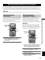 432
432
-
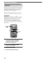 433
433
-
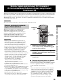 434
434
-
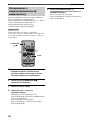 435
435
-
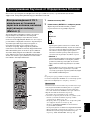 436
436
-
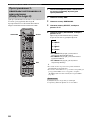 437
437
-
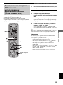 438
438
-
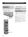 439
439
-
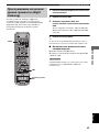 440
440
-
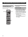 441
441
-
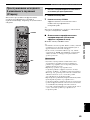 442
442
-
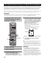 443
443
-
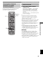 444
444
-
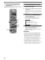 445
445
-
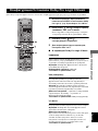 446
446
-
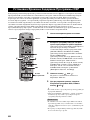 447
447
-
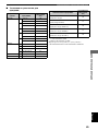 448
448
-
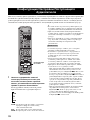 449
449
-
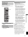 450
450
-
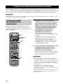 451
451
-
 452
452
-
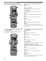 453
453
-
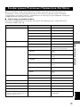 454
454
-
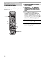 455
455
-
 456
456
-
 457
457
-
 458
458
-
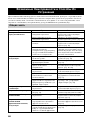 459
459
-
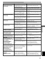 460
460
-
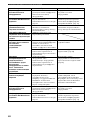 461
461
-
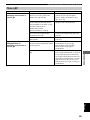 462
462
-
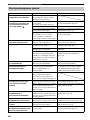 463
463
-
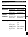 464
464
-
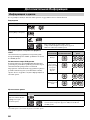 465
465
-
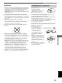 466
466
-
 467
467
-
 468
468
-
 469
469
-
 470
470
-
 471
471
-
 472
472
-
 473
473
-
 474
474
-
 475
475
-
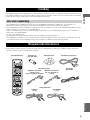 476
476
-
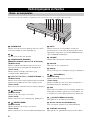 477
477
-
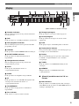 478
478
-
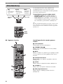 479
479
-
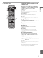 480
480
-
 481
481
-
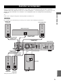 482
482
-
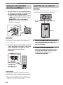 483
483
-
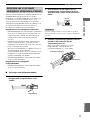 484
484
-
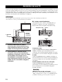 485
485
-
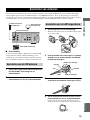 486
486
-
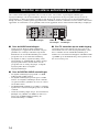 487
487
-
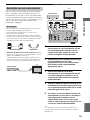 488
488
-
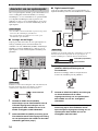 489
489
-
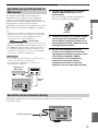 490
490
-
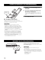 491
491
-
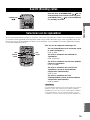 492
492
-
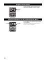 493
493
-
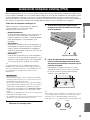 494
494
-
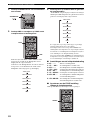 495
495
-
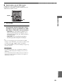 496
496
-
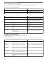 497
497
-
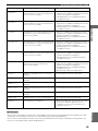 498
498
-
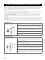 499
499
-
 500
500
-
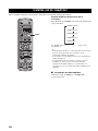 501
501
-
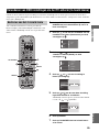 502
502
-
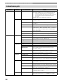 503
503
-
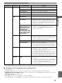 504
504
-
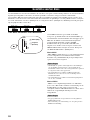 505
505
-
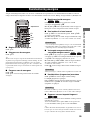 506
506
-
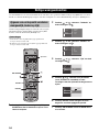 507
507
-
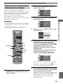 508
508
-
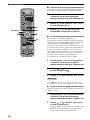 509
509
-
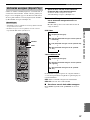 510
510
-
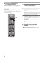 511
511
-
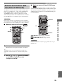 512
512
-
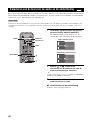 513
513
-
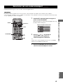 514
514
-
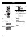 515
515
-
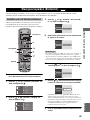 516
516
-
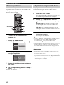 517
517
-
 518
518
-
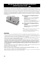 519
519
-
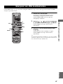 520
520
-
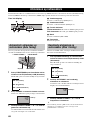 521
521
-
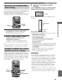 522
522
-
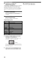 523
523
-
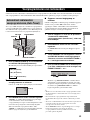 524
524
-
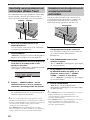 525
525
-
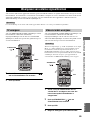 526
526
-
 527
527
-
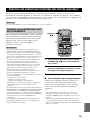 528
528
-
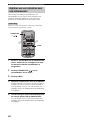 529
529
-
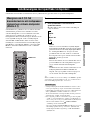 530
530
-
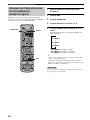 531
531
-
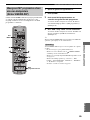 532
532
-
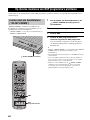 533
533
-
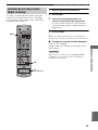 534
534
-
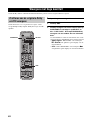 535
535
-
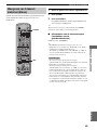 536
536
-
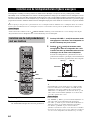 537
537
-
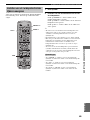 538
538
-
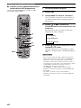 539
539
-
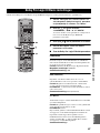 540
540
-
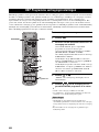 541
541
-
 542
542
-
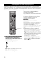 543
543
-
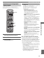 544
544
-
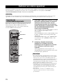 545
545
-
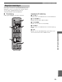 546
546
-
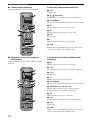 547
547
-
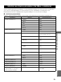 548
548
-
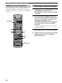 549
549
-
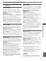 550
550
-
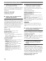 551
551
-
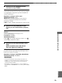 552
552
-
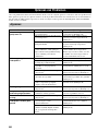 553
553
-
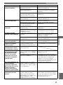 554
554
-
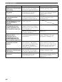 555
555
-
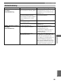 556
556
-
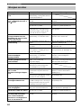 557
557
-
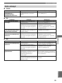 558
558
-
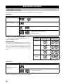 559
559
-
 560
560
-
 561
561
-
 562
562
-
 563
563
-
 564
564
-
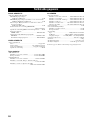 565
565
-
 566
566
-
 567
567


diğer dillerde
- français: Yamaha DVR-S150 Le manuel du propriétaire
- italiano: Yamaha DVR-S150 Manuale del proprietario
- svenska: Yamaha DVR-S150 Bruksanvisning
- Deutsch: Yamaha DVR-S150 Bedienungsanleitung
- English: Yamaha DVR-S150 Owner's manual
- dansk: Yamaha DVR-S150 Brugervejledning
- русский: Yamaha DVR-S150 Инструкция по применению
- Nederlands: Yamaha DVR-S150 de handleiding
- română: Yamaha DVR-S150 Manualul proprietarului