
MULTITRACK CASSETTE RECORDER
Owner’s Manual
45678321
0
ST-INPUT
10
ST-INPUT
010
ST-INPUT
010
9-10 11-12 13-14
1
2
3
4
2
1
2
3
4
3
4
010
010
GROUP
MASTER
GROUP 1
GROUP 2
010
GROUP 3
010
GROUP 4
TAPE IN
MIX LEVEL
010
MONITOR LEVEL
MIN MAX
TAPE IN
GROUP
TO
MONITOR
TO
STEREO
STEREO
CUE
MONITOR
SELECT
1 3
2 4
ON
OFF
CUE MIX
TO STEREO
0
10
9
8
7
6
5
4
3
2
1
0
10
9
8
7
6
5
4
3
2
1
MULTITRACK CASSETTE RECORDER
L R
TRACK
STEREO
+9
+6
+3
0dB
–3
–6
–10
–20
+9
+6
+3
0dB
–3
–6
–10
–20
REC
1
2
TAPE
REPEAT
MEMO
IN
OUT
dbx
SYNC
123456 78
AUTO PUNCH
NOISE REDUCTION SYSTEM
–
0
+
TAPE SPEED REC SELECT
VARI
FIX
GROUP
AUTO
PUNCH I/O
CLEARSYNC
CHECK REPEAT
RESET
MEMO 1
MEMO 2
RTZ
LOC 1
LOC 2
FF STOPREWPLAYREHE
PHONES PUNCH I/O
REC/PAUSE
1
1
5
2
2
6
3
3
7
4
4
8
STEREO
12345678
GAIN
LINE MIC
HIGH
–12 +12
FREQ
250 5k
MID
–12 +12
LOW
–12 +12
AUX
1
010
AUX
2
010
CUE
LR
010
PAN
L
ODD
R
EVEN
GROUP ASSIGN
12 34
PEAK
SIGNAL
0
10
9
8
7
6
5
4
3
2
1
P
A
N
L
E
V
E
L
GAIN
LINE MIC
HIGH
–12 +12
FREQ
250 5k
MID
–12 +12
LOW
–12 +12
AUX
1
010
AUX
2
010
CUE
LR
010
PAN
L
ODD
R
EVEN
GROUP ASSIGN
12 34
PEAK
SIGNAL
0
10
9
8
7
6
5
4
3
2
1
P
A
N
L
E
V
E
L
GAIN
LINE MIC
HIGH
–12 +12
FREQ
250 5k
MID
–12 +12
LOW
–12 +12
AUX
1
010
AUX
2
010
CUE
LR
010
PAN
L
ODD
R
EVEN
GROUP ASSIGN
12 34
PEAK
SIGNAL
0
10
9
8
7
6
5
4
3
2
1
P
A
N
L
E
V
E
L
GAIN
LINE MIC
HIGH
–12 +12
FREQ
250 5k
MID
–12 +12
LOW
–12 +12
AUX
1
010
AUX
2
010
CUE
LR
010
PAN
L
ODD
R
EVEN
GROUP ASSIGN
12 34
PEAK
SIGNAL
0
10
9
8
7
6
5
4
3
2
1
P
A
N
L
E
V
E
L
HIGH
–12 +12
FREQ
250 5k
MID
–12 +12
LOW
–12 +12
AUX
1
010
AUX
2
010
CUE
LR
010
PAN
L
ODD
R
EVEN
GROUP ASSIGN
12 34
PEAK
SIGNAL
0
10
9
8
7
6
5
4
3
2
1
P
A
N
L
E
V
E
L
HIGH
–12 +12
FREQ
250 5k
MID
–12 +12
LOW
–12 +12
AUX
1
010
AUX
2
010
CUE
LR
010
PAN
L
ODD
R
EVEN
GROUP ASSIGN
12 34
PEAK
SIGNAL
0
10
9
8
7
6
5
4
3
2
1
P
A
N
L
E
V
E
L
HIGH
–12 +12
FREQ
250 5k
MID
–12 +12
LOW
–12 +12
AUX
1
010
AUX
2
010
CUE
LR
010
PAN
L
ODD
R
EVEN
GROUP ASSIGN
12 34
PEAK
SIGNAL
0
10
9
8
7
6
5
4
3
2
1
P
A
N
L
E
V
E
L
HIGH
–12 +12
FREQ
250 5k
MID
–12 +12
LOW
–12 +12
AUX
1
010
AUX
2
010
CUE
LR
010
PAN
L
ODD
R
EVEN
GROUP ASSIGN
12 34
PEAK
SIGNAL
0
10
9
8
7
6
5
4
3
2
1
P
A
N
L
E
V
E
L
1
TAPE
MIC/
LINE
TAPE FLIP
MIC/
LINE
TAPE
MIC/
LINE
TAPE FLIP
MIC/
LINE
TAPE
MIC/
LINE
TAPE FLIP
FLIP FLIP FLIP FLIP
MIC/
LINE
TAPE
MIC/
LINE
TAPE FLIP
MIC/
LINE
TAPELINE
TAPE LINE
TAPELINE
TAPE LINE
TAPELINE
TAPE LINE
TAPELINE
TAPE LINE
E

FCC INFORMATION (U.S.A.)
1. IMPORTANT NOTICE: DO NOT MODIFY THIS UNIT!
This product, when installed as indicated in the instructions contained in this manual, meets FCC requirements. Modifications not expressly approved by Yamaha
may void your authority, granted by the FCC, to use the product.
2. IMPORTANT: When connecting this product to accessories and/or another product use only high quality shielded cables. Cable/s supplied with this product MUST
be used. Follow all installation instructions. Failure to follow instructions could void your FCC authorization to use this product in the USA.
3. NOTE: This product has been tested and found to comply with the requirements listed in FCC Regulations, Part 15 for Class “B” digital devices. Compliance with
these requirements provides a reasonable level of assurance that your use of this product in a residential environment will not result in harmful interference with
other electronic devices. This equipment generates/uses radio frequencies and, if not installed and used according to the instructions found in the users manual, may
cause interference harmful to the operation of other electronic devices. Compliance with FCC regulations does not guarantee that interference will not occur in all
installations. If this product is found to be the source of interference, which can be determined by turning the unit “OFF” and “ON”, please try to eliminate the
problem by using one of the following measures:
Relocate either this product or the device that is being affected by the interference.
Utilize power outlets that are on different branch (circuit breaker or fuse) circuits or install AC line filter/s.
In the case of radio or TV interference, relocate/reorient the antenna. If the antenna lead-in is 300 ohm ribbon lead, change the lead-in to coaxial type cable.
If these corrective measures do not produce satisfactory results, please contact the local retailer authorized to distribute this type of product. If you can not locate the
appropriate retailer, please contact Yamaha Corporation of America, Electronic Service Division, 6600 Orangethorpe Ave, Buena Park, CA 90620
* This applies only to products distributed by YAMAHA CORPORATION OF AMERICA.
IMPORTANT NOTICE FOR
THE UNITED KINGDOM
Connecting the Plug and Cord
IMPORTANT: The wires in this mains lead are coloured in accordance
with the following code:
BLUE : NEUTRAL
BROWN : LIVE
As the colours of the wires in the mains lead of this apparatus may not
correspond with the coloured markings identifying the terminals in your
plug proceed as follows:
The wire which is coloured BLUE must be connected to the terminal
which is marked with the letter N or coloured BLACK.
The wire which is coloured BROWN must be connected to the terminal
which is marked with the letter L or coloured RED.
Making sure that neither core is connected to the earth terminal of the
three pin plug.
* This applies only to products distributed by YAMAHA - KEMBLE
MUSIC (U.K.) LTD.

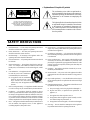
• Explanation of Graphical Symbols
The exclamation point within an equilateral tri-
angle is intended to alert the user to the presence of
important operating and maintenance (servicing)
instructions in the literature accompanying the
product.
The lightning flash with arrowhead symbol within
an equilateral triangle is intended to alert the user
to the presence of uninsulated “dangerous volt-
age” within the product’s enclosure that may be of
sufficient magnitude to constitute a risk of electric
shock to persons.
CAUTION: TO REDUCE THE RISK OF
ELECTRIC SHOCK, DO NOT REMOVE
COVER (OR BACK). NO USER-SERVICEABLE
PARTS INSIDE. REFER SERVICING TO
QUALIFIED SERVICE PERSONNEL.
CAUTION
RISK OF ELECTRIC SHOCK
DO NOT OPEN
1. Read Instructions — All the safety and operating instructions
should be read before the appliance is operated.
2. Retain Instructions — The safety and operating instructions
should be retained for future reference.
3. Heed Warnings — All warnings on the appliance and in the
operating instructions should be adhered to.
4. Follow Instructions — All operating and use instructions should
be followed.
5. Water and Moisture — The appliance should not be used near
water – for example, near a bathtub, washbowl, kitchen sink,
laundry tub, in a wet basement, or near a swimming pool, and the
like.
6. Carts and Stands — The appliance should
be used only with a cart or stand that is
recommended by the manufacturer.
6A An appliance and cart combination
should be moved with care. Quick
stops, excessive force, and uneven
surfaces may cause the appliance and cart combination to
overturn.
7. Wall or Ceiling Mounting — The appliance should be mounted
to a wall or ceiling only as recommended by the manufacturer.
8. Ventilation — The appliance should be situated so that its
location or position does not interfere with its proper ventilation.
For example, the appliance should not be situated on a bed, sofa,
rug, or similar surface that may block the ventilation openings;
or, placed in a built-in installation, such as a bookcase or cabinet
that may impede the flow of air through the ventilation openings.
9. Heat — The appliance should be situated away from heat sources
such as radiators, heat registers, stoves, or other appliances
(including amplifiers) that produce heat.
10. Power Sources — The appliance should be connected to a power
supply only of the type described in the operating instructions or
as marked on the appliance.
11. Grounding or Polarization — The precautions that should be
taken so that the grounding or polarization means of an appliance
is not defeated.
12. Power-Cord Protection — Power-supply cords should be routed
so that they are not likely to be walked on or pinched by items
placed upon or against them, paying particular attention to cords
at plugs, convenience receptacles, and the point where they exit
from the appliance.
13. Cleaning — The appliance should be cleaned only as recom-
mended by the manufacturer.
14. Nonuse Periods — The power cord of the appliance should be
unplugged from the outlet when left unused for a long period of
time.
15. Object and Liquid Entry — Care should be taken so that objects
do not fall and liquids are not spilled into the enclosure through
openings.
16. Damage Requiring Service — The appliance should be serviced
by qualified service personnel when:
A. The power-supply cord or the plug has been damaged; or
B. Objects have fallen, or liquid has been spilled into the
appliance; or
C. The appliance has been exposed to rain; or
D. The appliance does not appear to operate normally or exhib-
its a marked change in performance; or
E. The appliance has been dropped, or the enclosure damaged.
17. Servicing — The user should not attempt service the appliance
beyond that described in the operating instructions.
SAFETY INSTRUCTIONS

iii
MT8XII—Owner’s Manual
Important
Read the Following Before Operating MT8XII
Warnings
• Do not locate MT8XII in a place subject to excessive heat or in direct sunlight. This could be
a fire hazard.
• Do not place MT8XII in a place subject to excessive humidity or dust. This could be a fire
and electrical shock hazard.
• Connect the supplied AC power cord only to an AC outlet of the type stated in this
Owner’s
Manual
or as marked on the main unit. Failure to do so is a fire and electrical shock hazard.
• Do not plug several devices into the same AC outlet. This can overload the AC outlet, and
can be a fire and electrical shock hazard. It may also affect the performance of some devices.
• Do not place heavy objects on the power cord. A damaged power cord is a potential fire and
electrical shock hazard.
• If the power cord is damaged (i.e., cut or a bare wire is exposed), ask your dealer for a
replacement. Using MT8XII in this condition is a fire and shock hazard.
• Hold the AC power cord plug when disconnecting from an AC outlet. Never pull the cord.
Damaging the power cord in this way is a potential fire and electrical shock hazard.
• Do not place small metal objects on top of MT8XII. Metal objects inside MT8XII are a fire
and electrical shock hazard.
• Do not block the MT8XII ventilation holes. MT8XII has ventilation holes at the rear to pre-
vent the internal temperature from rising. Blocked ventilation holes are a fire hazard.
• Do not try to modify MT8XII. This could be a fire and electrical shock hazard.
• MT8XII operating temperature is between 5˚C and 35˚C (41˚F and 95˚F).
Cautions
• Turn off all audio devices and speakers when connecting to MT8XII. Refer to the owner’s
manual for each device. Use the correct cables and connect as specified.
• MT8XII is a precision device. Handle it with care.
• If you notice any abnormality—such as smoke, odor, or noise—turn off MT8XII immedi-
ately. Remove the AC power cord from the AC outlet. Confirm that the abnormality is no
longer present. Consult your dealer for repair. Using MT8XII in this condition is a fire and
shock hazard.
• If a foreign object or water gets inside MT8XII, turn it off immediately. Remove the AC
power cord from the AC outlet. Consult your dealer for repair. Using MT8XII in this condi-
tion is a fire and electrical shock hazard.
• If you plan not to use MT8XII for a long period of time (such as when you are on vacation),
remove the AC power cord from the AC outlet. Leaving MT8XII connected is a fire hazard.
• Do not use benzene, thinner, cleaning detergent, or a chemical cloth to clean MT8XII.
• Use only a soft, dry cloth to clean MT8XII.

iv
MT8XII—Owner’s Manual
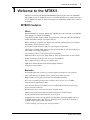
Interference
MT8XII uses high-frequency digital circuits that may cause interference on radios and televi-
sions placed close to it. If interference does occur, relocate the affected equipment.
Copyright
© 1996 Yamaha Corporation. All rights reserved.
No part of the MT8XII software or this Owner’s Manual may be reproduced or distributed in
any form or by any means without the prior written authorization of Yamaha Corporation.
Trademarks
The dbx noise reduction system is manufactured based on a patent license from THAT
Corporation.
dbx is a trademark of Carillon Electronics Corporation.
All other trademarks are the property of their respective holders.
Packing List
The MT8XII package should contain the following items. Make sure that you have them all.
• MT8XII Multitrack Recorder
• AC power cord
• Cleaning kit
• This Owner’s Manual
Contact your Yamaha dealer if something is missing.
Keep This Manual For Future Reference

v
MT8XII—Owner’s Manual
Table of Contents
1. Welcome to the MT8XII . . . . . . . . . . . . . . 1
MT8XII Features . . . . . . . . . . . . . . . . . . . . . . . . . . . . . . . . . . . . . . . . . . . . . . . . 1
Buying Cassette Tapes for the MT8XII . . . . . . . . . . . . . . . . . . . . . . . . . . . . . . 2
MT8XII Recording Format . . . . . . . . . . . . . . . . . . . . . . . . . . . . . . . . . . . . . . . 2
About dbx Noise Reduction . . . . . . . . . . . . . . . . . . . . . . . . . . . . . . . . . . . . . . . 2
MT8XII Maintenance . . . . . . . . . . . . . . . . . . . . . . . . . . . . . . . . . . . . . . . . . . . . 2
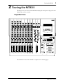
2. Touring the MT8XII . . . . . . . . . . . . . . . . . . 3
Topside View . . . . . . . . . . . . . . . . . . . . . . . . . . . . . . . . . . . . . . . . . . . . . . . . . . . 3
Input Channels . . . . . . . . . . . . . . . . . . . . . . . . . . . . . . . . . . . . . . . . . . . . . . . . . 4
Stereo Inputs . . . . . . . . . . . . . . . . . . . . . . . . . . . . . . . . . . . . . . . . . . . . . . . . . . . 5
Master Section . . . . . . . . . . . . . . . . . . . . . . . . . . . . . . . . . . . . . . . . . . . . . . . . . . 6
Display . . . . . . . . . . . . . . . . . . . . . . . . . . . . . . . . . . . . . . . . . . . . . . . . . . . . . . . . 7
Transport Section . . . . . . . . . . . . . . . . . . . . . . . . . . . . . . . . . . . . . . . . . . . . . . . 8
Rear Panel Connectors . . . . . . . . . . . . . . . . . . . . . . . . . . . . . . . . . . . . . . . . . . . 10
Front Connectors . . . . . . . . . . . . . . . . . . . . . . . . . . . . . . . . . . . . . . . . . . . . . . . 12
3. The First Session . . . . . . . . . . . . . . . . . . . 13
Connecting the Power Cord . . . . . . . . . . . . . . . . . . . . . . . . . . . . . . . . . . . . . . . 13
Turning On the MT8XII . . . . . . . . . . . . . . . . . . . . . . . . . . . . . . . . . . . . . . . . . 13
Loading a Tape . . . . . . . . . . . . . . . . . . . . . . . . . . . . . . . . . . . . . . . . . . . . . . . . . 13
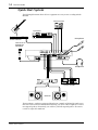
Quick-Start System . . . . . . . . . . . . . . . . . . . . . . . . . . . . . . . . . . . . . . . . . . . . . . 14
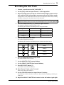
Recording the First Track . . . . . . . . . . . . . . . . . . . . . . . . . . . . . . . . . . . . . . . . . 15
Listening to the First Track . . . . . . . . . . . . . . . . . . . . . . . . . . . . . . . . . . . . . . . 16
Overdubbing . . . . . . . . . . . . . . . . . . . . . . . . . . . . . . . . . . . . . . . . . . . . . . . . . . . 16
Mixdown . . . . . . . . . . . . . . . . . . . . . . . . . . . . . . . . . . . . . . . . . . . . . . . . . . . . . . 18
Multi-Source Mixing . . . . . . . . . . . . . . . . . . . . . . . . . . . . . . . . . . . . . . . . . . . . 19
An Overview of Multitrack Recording . . . . . . . . . . . . . . . . . . . . . . . . . . . . . . 20
About Monitoring . . . . . . . . . . . . . . . . . . . . . . . . . . . . . . . . . . . . . . . . . . . . . . . 21
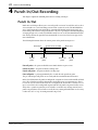
4. Punch In/Out Recording . . . . . . . . . . . . . 22
Punch In/Out . . . . . . . . . . . . . . . . . . . . . . . . . . . . . . . . . . . . . . . . . . . . . . . . . . . 22
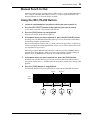
Manual Punch In/Out . . . . . . . . . . . . . . . . . . . . . . . . . . . . . . . . . . . . . . . . . . . 23
Using the REC/PAUSE Button . . . . . . . . . . . . . . . . . . . . . . . . . . . . . . . . . . . . 23
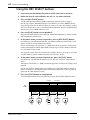
Using the REC SELECT buttons . . . . . . . . . . . . . . . . . . . . . . . . . . . . . . . . . . . 24
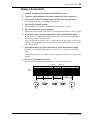
Using a Footswitch . . . . . . . . . . . . . . . . . . . . . . . . . . . . . . . . . . . . . . . . . . . . . . 25
Auto Punch In/Out . . . . . . . . . . . . . . . . . . . . . . . . . . . . . . . . . . . . . . . . . . . . . . 26
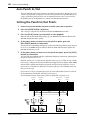
Setting the Punch In/Out Points . . . . . . . . . . . . . . . . . . . . . . . . . . . . . . . . . . . 26
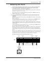
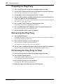
Rehearsing Auto Punch . . . . . . . . . . . . . . . . . . . . . . . . . . . . . . . . . . . . . . . . . . 27
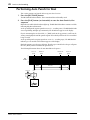
Performing Auto Punch for Real . . . . . . . . . . . . . . . . . . . . . . . . . . . . . . . . . . . 28
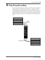
5. Ping-Pong Recording . . . . . . . . . . . . . . . 29
Preparing for Ping-Pong . . . . . . . . . . . . . . . . . . . . . . . . . . . . . . . . . . . . . . . . . . 30
Rehearsing the Ping-Pong . . . . . . . . . . . . . . . . . . . . . . . . . . . . . . . . . . . . . . . . 30
Performing the Ping-Pong for Real . . . . . . . . . . . . . . . . . . . . . . . . . . . . . . . . . 30
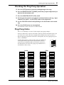
Checking the Ping-Pong Operation . . . . . . . . . . . . . . . . . . . . . . . . . . . . . . . . 31
Ping-Pong Notes . . . . . . . . . . . . . . . . . . . . . . . . . . . . . . . . . . . . . . . . . . . . . . . . 31
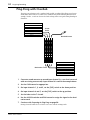
Ping-Pong with Overdub . . . . . . . . . . . . . . . . . . . . . . . . . . . . . . . . . . . . . . . . . 32

vi
MT8XII—Owner’s Manual
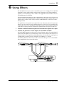
6. Using Effects . . . . . . . . . . . . . . . . . . . . . . 33
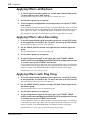
Applying Effects at Mixdown . . . . . . . . . . . . . . . . . . . . . . . . . . . . . . . . . . . . . 34
Applying Effects when Recording . . . . . . . . . . . . . . . . . . . . . . . . . . . . . . . . . 34
Applying Effects with Ping-Pong . . . . . . . . . . . . . . . . . . . . . . . . . . . . . . . . . . 34
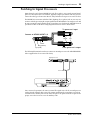
Patching In Signal Processors . . . . . . . . . . . . . . . . . . . . . . . . . . . . . . . . . . . . . 35
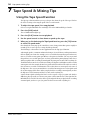
7. Tape Speed & Mixing Tips . . . . . . . . . . . 36
Using the Tape Speed Function . . . . . . . . . . . . . . . . . . . . . . . . . . . . . . . . . . . 36
Mixing Tips . . . . . . . . . . . . . . . . . . . . . . . . . . . . . . . . . . . . . . . . . . . . . . . . . . . 37
8. Quick Locate & Repeat Playback . . . . . . . 38
RTZ (Return To Zero) . . . . . . . . . . . . . . . . . . . . . . . . . . . . . . . . . . . . . . . . . . 38
Memo 1/Memo 2 . . . . . . . . . . . . . . . . . . . . . . . . . . . . . . . . . . . . . . . . . . . . . . . 38
Entering the Memo Points . . . . . . . . . . . . . . . . . . . . . . . . . . . . . . . . . . . . . . . 38
Locating the Memo Points . . . . . . . . . . . . . . . . . . . . . . . . . . . . . . . . . . . . . . . 38
Checking the Memo Points . . . . . . . . . . . . . . . . . . . . . . . . . . . . . . . . . . . . . . 38
Clearing the Memo Points . . . . . . . . . . . . . . . . . . . . . . . . . . . . . . . . . . . . . . . 38
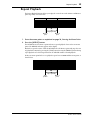
Repeat Playback . . . . . . . . . . . . . . . . . . . . . . . . . . . . . . . . . . . . . . . . . . . . . . . . 39
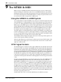
9. The MT8XII & MIDI . . . . . . . . . . . . . . . . . 40
Using the MT8XII in a MIDI System . . . . . . . . . . . . . . . . . . . . . . . . . . . . . . . 40
SYNC Signal Formats . . . . . . . . . . . . . . . . . . . . . . . . . . . . . . . . . . . . . . . . . . . 40
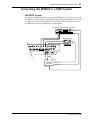
Connecting the MT8XII to a MIDI System . . . . . . . . . . . . . . . . . . . . . . . . . . 41
Striping the Tape . . . . . . . . . . . . . . . . . . . . . . . . . . . . . . . . . . . . . . . . . . . . . . . 43
Synchronized Operation . . . . . . . . . . . . . . . . . . . . . . . . . . . . . . . . . . . . . . . . . 43
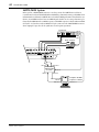
10. MT8XII Applications . . . . . . . . . . . . . . . 44
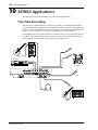
One-Take Recording . . . . . . . . . . . . . . . . . . . . . . . . . . . . . . . . . . . . . . . . . . . . 44
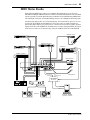
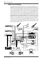
MIDI Home Studio . . . . . . . . . . . . . . . . . . . . . . . . . . . . . . . . . . . . . . . . . . . . . 45
Multi-Source Mixing . . . . . . . . . . . . . . . . . . . . . . . . . . . . . . . . . . . . . . . . . . . . 46
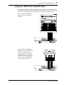
Using the TAPE OUT/GROUP OUTs . . . . . . . . . . . . . . . . . . . . . . . . . . . . . . 47
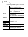
Troubleshooting . . . . . . . . . . . . . . . . . . . . . 48
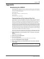
Appendix . . . . . . . . . . . . . . . . . . . . . . . . . . . 49
Maintaining the MT8XII . . . . . . . . . . . . . . . . . . . . . . . . . . . . . . . . . . . . . . . . 49
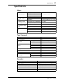
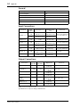
Specifications . . . . . . . . . . . . . . . . . . . . . . . . . . . . . . . . . . . . . . . . . . . . . . . . . . 51
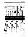
Block Diagram . . . . . . . . . . . . . . . . . . . . . . . . . . . . . . . . . . . . . . . . . . . . . . . . . 53
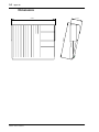
Dimensions . . . . . . . . . . . . . . . . . . . . . . . . . . . . . . . . . . . . . . . . . . . . . . . . . . . 54
Glossary . . . . . . . . . . . . . . . . . . . . . . . . . . . . 55

Welcome to the MT8XII
1
MT8XII—Owner’s Manual
1
Welcome to the MT8XII
Thank you for choosing the Yamaha MT8XII Multitrack Cassette Recorder. The MT8XII is a
high-quality, easy-to-use multitrack cassette recorder that will allow you to capture your music
at a very high level of quality. To take best advantage of your MT8XII, read this
Owner’s Manual
thoroughly.
MT8XII Features
Mixer
The MT8XII mixer has 14 inputs and 4 groups. Including the 8 tape tracks and stereo TAPE IN,
up to 20 inputs are available for mixdown.
• Continuously variable GAIN controls on input channels 1 through 4 allow the MT8XII to
handle microphone and line-level signals with ease.
• Balanced XLR-type and phone jack inputs with switchable phantom power for condenser
microphones on input channels 1 and 2.
• Insert jacks on input channels 1 and 2 for external processor patching.
• Musical three-band EQ (High, Mid, Low) with sweepable Mid on each input channel pro-
vides flexible tone-shaping capabilities.
• Two auxiliary sends for external effects processor patching.
• FLIP button allows you to route input signals to either the channel fader or CUE controls.
• Flexible monitoring of Groups, CUE, Stereo bus, and TAPE IN.
• Direct outputs for direct connection to another mixer.
• TAPE IN to monitor facility for monitoring during mixdown.
• Long-throw accurate faders.
Recorder
The MT8XII eight-track recorder is a precision engineered compact cassette transport.
• Logic-controlled tape mechanism ensures smooth and reliable operation.
• Hard Permalloy record–play head for long life and high performance.
• dbx™ noise reduction system provides a signal-to-noise ratio in excess of 80 dB.
• Variable pitch of approximately
±
12%.
• Two-color FLD (Fluorescent Display) shows recording and playback levels, plus a tape
counter and other indicators.
• RTZ (Return To Zero) and two memo points for quick locate.
• Manual, footswitch, and automatic punch in/out functions, all with rehearse.
• Repeat playback and Auto Punch In/Out rehearsal repeat.
• Stripping Track 8 with a sync signal allows the MT8XII to synchronize MIDI sequencers
and MIDI drum machines. The dbx noise reduction can be turned off just for Track 8,
ensuring reliable synchronization operation.
• 9.5 cm/second tape speed for greater sonic performance.

2
Welcome to the MT8XII
MT8XII—Owner’s Manual
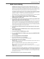
Buying Cassette Tapes for the MT8XII
It’s important that you buy the correct type of cassette tape for use with your MT8XII. You
should buy high-quality Type II (High Bias, 70
µ
s EQ) chrome cassettes of 90 minutes or less,
such as TDK SA or Maxell UD-II or UD-XLIIS. Do not use metal tapes or 120 minute tapes. At
normal speed, a 60-minute cassette provides about 15 minutes of recording time. That’s because
the tape runs at twice the speed of a normal cassette recorder and you can use only one side of
the tape. The following table shows the available recording times with three standard tapes sizes.
MT8XII Recording Format
Although the MT8XII uses the same type of cassettes as those used with normal cassette record-
ers, MT8XII tapes are not compatible with normal cassette players. A normal cassette recorder
uses only two tracks (i.e., left and right stereo channels) and both tracks are recorded simulta-
neously. The MT8XII, on the other hand, can record eight tracks on a standard audio cassette.
Even more importantly, you can record and playback these tracks individually. You can record
up to four tracks simultaneously, or one at a time (a technique called overdub recording).
Another major difference is that the MT8XII uses only one side of the cassette. There is no B
side. If you turn over an MT8XII cassette you’ll hear the tracks play backwards. This is because
the MT8XII uses the full width of the tape to record eight tracks. The tape speed is also different.
Normal cassette recorders run at 4.8 cm/second. Whereas the MT8XII runs at 9.5 cm/second,
providing greater sonic performance.
About dbx Noise Reduction
The MT8XII uses the dbx noise reduction system to reduce tape hiss and keep your recordings
clean and crisp. For the best performance, it’s recommended that you use the dbx noise reduc-
tion for all your recordings. You should always use the dbx noise reduction system to play back
tapes that were recorded with the dbx system on.
MT8XII Maintenance
The MT8XII requires regular maintenance to remain in top working condition. This consists
of cleaning and demagnetizing the record–play head and other metal parts that are in contact
with the cassette tape. See
Maintaining the MT8XII
on page 49 for more information.
Cassette Tape
MT8XII Recording Time
(approximate)
C90 22.5 minutes
C60 15 minutes
C46 11.5 minutes

Touring the MT8XII
3
MT8XII—Owner’s Manual
2
Touring the MT8XII
This chapter takes you on a tour of the MT8XII, identifying the various parts to help you become
familiar with your new recorder.
Topside View
The individual sections of the MT8XII are explained on the following pages.
45678321
0
ST-INPUT
10
ST-INPUT
010
ST-INPUT
010
9-10 11-12 13-14
1
2
3
4
2
1
2
3
4
3
4
010
010
GROUP
MASTER
GROUP 1
GROUP 2
010
GROUP 3
010
GROUP 4
TAPE IN
MIX LEVEL
010
MONITOR LEVEL
MIN MAX
TAPE IN
GROUP
TO
MONITOR
TO
STEREO
STEREO
CUE
MONITOR
SELECT
1 3
2 4
ON
OFF
CUE MIX
TO STEREO
0
10
9
8
7
6
5
4
3
2
1
0
10
9
8
7
6
5
4
3
2
1
MULTITRACK CASSETTE RECORDER
L R
TRACK
STEREO
+9
+6
+3
0dB
–3
–6
–10
–20
+9
+6
+3
0dB
–3
–6
–10
–20
REC
1
2
TAPE
REPEATMEMO
IN
OUT
dbx
SYNC
123456 78
AUTO PUNCH
NOISE REDUCTION SYSTEM
–
0
+
TAPE SPEED REC SELECT
VARI
FIX
GROUP
AUTO
PUNCH I/O
CLEARSYNC
CHECK REPEAT
RESET
MEMO 1
MEMO 2
RTZ
LOC 1
LOC 2
FF STOPREWPLAYREHE
PHONES PUNCH I/O
REC/PAUSE
1
1
5
2
2
6
3
3
7
4
4
8
STEREO
12345678
GAIN
LINE MIC
HIGH
–12 +12
FREQ
250 5k
MID
–12 +12
LOW
–12 +12
AUX
1
010
AUX
2
010
CUE
LR
010
PAN
L
ODD
R
EVEN
GROUP ASSIGN
12 34
PEAK
SIGNAL
0
10
9
8
7
6
5
4
3
2
1
P
A
N
L
E
V
E
L
GAIN
LINE MIC
HIGH
–12 +12
FREQ
250 5k
MID
–12 +12
LOW
–12 +12
AUX
1
010
AUX
2
010
CUE
LR
010
PAN
L
ODD
R
EVEN
GROUP ASSIGN
12 34
PEAK
SIGNAL
0
10
9
8
7
6
5
4
3
2
1
P
A
N
L
E
V
E
L
GAIN
LINE MIC
HIGH
–12 +12
FREQ
250 5k
MID
–12 +12
LOW
–12 +12
AUX
1
010
AUX
2
010
CUE
LR
010
PAN
L
ODD
R
EVEN
GROUP ASSIGN
12 34
PEAK
SIGNAL
0
10
9
8
7
6
5
4
3
2
1
P
A
N
L
E
V
E
L
GAIN
LINE MIC
HIGH
–12 +12
FREQ
250 5k
MID
–12 +12
LOW
–12 +12
AUX
1
010
AUX
2
010
CUE
LR
010
PAN
L
ODD
R
EVEN
GROUP ASSIGN
12 34
PEAK
SIGNAL
0
10
9
8
7
6
5
4
3
2
1
P
A
N
L
E
V
E
L
HIGH
–12 +12
FREQ
250 5k
MID
–12 +12
LOW
–12 +12
AUX
1
010
AUX
2
010
CUE
LR
010
PAN
L
ODD
R
EVEN
GROUP ASSIGN
12 34
PEAK
SIGNAL
0
10
9
8
7
6
5
4
3
2
1
P
A
N
L
E
V
E
L
HIGH
–12 +12
FREQ
250 5k
MID
–12 +12
LOW
–12 +12
AUX
1
010
AUX
2
010
CUE
LR
010
PAN
L
ODD
R
EVEN
GROUP ASSIGN
12 34
PEAK
SIGNAL
0
10
9
8
7
6
5
4
3
2
1
P
A
N
L
E
V
E
L
HIGH
–12 +12
FREQ
250 5k
MID
–12 +12
LOW
–12 +12
AUX
1
010
AUX
2
010
CUE
LR
010
PAN
L
ODD
R
EVEN
GROUP ASSIGN
12 34
PEAK
SIGNAL
0
10
9
8
7
6
5
4
3
2
1
P
A
N
L
E
V
E
L
HIGH
–12 +12
FREQ
250 5k
MID
–12 +12
LOW
–12 +12
AUX
1
010
AUX
2
010
CUE
LR
010
PAN
L
ODD
R
EVEN
GROUP ASSIGN
12 34
PEAK
SIGNAL
0
10
9
8
7
6
5
4
3
2
1
P
A
N
L
E
V
E
L
1
TAPE
MIC/
LINE
TAPE FLIP
MIC/
LINE
TAPE
MIC/
LINE
TAPE FLIP
MIC/
LINE
TAPE
MIC/
LINE
TAPE FLIP
FLIP FLIP FLIP FLIP
MIC/
LINE
TAPE
MIC/
LINE
TAPE FLIP
MIC/
LINE
TAPELINE
TAPE LINE
TAPELINE
TAPE LINE
TAPELINE
TAPE LINE
TAPELINE
TAPE LINE

4
Touring the MT8XII
MT8XII—Owner’s Manual
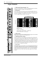
Input Channels
1
GAIN control (input channels 1–4)
This rotary control adjusts the sensitivity of the MIC/LINE input so that both
microphone and line-level signals can be handled with ease.
2
EQ controls
These rotary controls are used to boost and cut the high, middle, and low fre-
quency bands independently. The High and Low EQs are fixed frequency shelv-
ing types. The Mid EQ is a sweepable type. A flat setting (i.e., no boost or cut)
can be set quickly using the controls’ center detents.
3
AUX controls
These rotary controls are used to send the input channel signal to the AUX SEND
outputs for processing by external effects processors.
4
CUE PAN & LEVEL controls
These two controls are used to adjust the level and pan of the CUE signal. The
CUE signal source depends on the [FLIP] switch. With the [FLIP] switch set to
the up position, the signal source is the tape track (i.e., the signal being recorded
or played back). With the [FLIP] switch set to the down position, the signal source
is the MIC/LINE inputs. This setting is typically used during mixdown, when the
tape track signal is fed through the input channel. This allows you to connect
extra sound sources using the CUE controls.
5
FLIP switch
This switch is used to select the signal sources for the input channel and CUE con-
trols. With the [FLIP] switch in the up position, the MIC/LINE input signal is
fed to the input channel and the tape signal is fed to the CUE controls. With the
[FLIP] switch in the down position, however, this is reversed: the MIC/LINE
input signal is fed to the CUE controls and the tape signal is fed to the input
channel.
GAIN
LINE MIC
HIGH
–12 +12
FREQ
250 5k
MID
–12 +12
LOW
–12 +12
AUX
1
010
AUX
2
010
CUE
LR
010
PAN
L
ODD
R
EVEN
GROUP ASSIGN
12 34
PEAK
SIGNAL
0
10
9
8
7
6
5
4
3
2
1
P
A
N
L
E
V
E
L
9
3
5
7
4
8
6
1
2
TAPE
MIC/
LINE
TAPE FLIP
MIC/
LINE
20 20k100 1k 10k
0
-5
-10
-15
+15
+10
+5
Sweepable range
Response [dB]
Frequency [Hz]
HIGH: ±12 dB at
12 kHz—shelving type
MID: ±12 dB at 250 Hz–5 kHz—sweepable type
LOW: ±12 dB at 80 Hz—shelving type

Stereo Inputs
5
MT8XII—Owner’s Manual
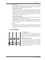
6
PAN control
This rotary control has two functions: For recording it’s used in conjunction with the GROUP
ASSIGN switches to assign the input channel signal to even and odd numbered groups. For mix-
down it’s used to pan (i.e., position) the signal in the stereo mix.
7
GROUP ASSIGN switches
These switches are used to assign (i.e., send) the input channel signal to groups. They work in
conjunction with the PAN control. For example, with GROUP ASSIGN switch [1–2] ON and
the PAN control set midway, the channel signal is sent equally to Groups 1 and 2. With the PAN
control turned fully counterclockwise (L/ODD), however, the channel signal is sent only to
Group 1. Likewise, when it is set fully clockwise, the signal is sent only to Group 2. The same
principle applies to GROUP ASSIGN switch [3–4].
8
SIGNAL & PEAK indicators
The SIGNAL indicator shows when a signal is present in the input channel. It lights up when
the signal is approximately 10 dB below the nominal level.
The PEAK indicator shows that a signal is about to clip. It lights up when the signal is 3 dB below
the clip point. Adjust the GAIN control so that the PEAK indicator lights up momentarily at
the loudest signals. For input channels 5–8 that do not have GAIN controls, adjust the output
level of the source device.
9
Fader
This fader has two functions: For recording it’s used to adjust the level of the input channel signal
that’s recorded to a track. For mixdown it’s used to balance the input channel signal relative to
the other input channel signals. For optimum performance, faders should be positioned about
the 7–8 mark.
Stereo Inputs
1
ST INPUT controls
These rotary controls are used to adjust the level of the Stereo
input signals that are sent to the Stereo bus for mixing. They’re
also used in conjunction with the GROUP ASSIGN switches to
adjust the level of the Stereo input signals that are assigned to
groups.
2
GROUP ASSIGN switches
These switches are used to assign (i.e., send) the Stereo input sig-
nals to the groups. The left-channel signal is sent to odd Groups
1 and 3. While the right-channel signal is sent to even Groups 2
and 4. The Stereo input signals could be the stereo output signals
from another mixer or external effects processor. Note that the
Stereo input signals are always sent to the Stereo bus for mixing
regardless of these switch settings.
0
ST-INPUT
10
ST-INPUT
010
ST-INPUT
010
9-10 11-12 13-14
1
2
3
4
1
2
3
4
1
2
3
4
1
2

6
Touring the MT8XII
MT8XII—Owner’s Manual
Master Section
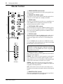
1
GROUP MASTER level controls
These rotary controls adjust the levels of the group signals that are
fed to the tracks.
2
CUE MIX TO STEREO switch
This switch is used to feed the CUE bus signals through to the Ste-
reo bus. It’s used for multi-source mixing at mixdown.
3
STEREO fader
This fader is used to adjust the level of the stereo signal that is sent
to the STEREO OUT. For optimum performance this fader
should be positioned about the 7–8 mark.
4
TAPE IN MIX LEVEL control
This control adjusts the level of the TAPE IN signal that is fed to
the Stereo bus when the TAPE IN switch is set to TO STEREO. It
has no effect on the TAPE IN signal when the TAPE IN switch is
set to TO MONITOR.
5
TAPE IN switch
This switch is used to assign the TAPE IN signal to either the Ste-
reo bus or monitor. Select TO MONITOR when you want to
monitor the output of the stereo master recorder during mix-
down.
Select TO STEREO when you want to use TAPE IN as an extra
stereo input and feed the signal into the stereo mix. Use the TAPE
IN MIX LEVEL control to adjust the level.
6
MONITOR SELECT switches
These switches are used to select the signal source for the MON-
ITOR OUT and headphones.
GROUP
—These switches select the Group buses as the monitor
source. This allows you to monitor signals assigned to tracks.
When only the [1–3] or [2–4] switch is pressed, the monitor signal
is mono. Press both switches to monitor stereo signals.
STEREO
—This switch selects the Stereo bus as the monitor
source. This allows you to monitor the STEREO OUT signal and
is typically used during mixdown.
CUE
—This switch selects the CUE bus as the monitor source.
This allows you to monitor track signals, which is useful for punch
in/out.
7
MONITOR LEVEL control
This rotary control adjusts the level of the monitor signal that is
sent to the MONITOR OUT and headphones.
Warning:
Make sure the TAPE IN switch is set to TO MON-
ITOR when recording through the TAPE INs and TAPE
OUTs. If it’s set to TO STEREO there will be a signal loop
and oscillation may occur.
010
010
GROUP
MASTER
GROUP 1
GROUP 2
010
GROUP 3
010
GROUP 4
TAPE IN
MIX LEVEL
010
MONITOR LEVEL
MIN MAX
TAPE IN
GROUP
TO
MONITOR
TO
STEREO
STEREO
CUE
MONITOR
SELECT
1 3
2 4
ON
OFF
CUE MIX
TO STEREO
0
10
9
8
7
6
5
4
3
2
1
0
10
9
8
7
6
5
4
3
2
1
STEREO
3
7
6
4
1
2
5

Display 7
MT8XII—Owner’s Manual
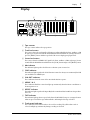
Display
1 Tape counter
The tape counter indicates the tape position.
2 Track level meters
These meters show the track signal levels during recording and playback from –20 dB to +9 dB
in eight steps. To turn on and off the Peak Hold function, hold down the [STOP] button and
press the [RESET] button. With no tape loaded, the meters display group signal levels.
3 Stereo level meters
These meters show the STEREO OUT signal levels from –20 dB to +9 dB in eight steps. To turn
on and off the Peak Hold function, hold down the [STOP] button and press the [RESET] button.
4 dbx indicator
This indicator lights up when the dbx noise reduction system is turned on.
5 SYNC indicator
This indicator lights up when the SYNC function is turned on. It stays on continuously for FSK
sync and flashes for SMPTE sync.
6 IN & OUT indicators
These indicators show the status of the Auto Punch In/Out sequence.
7 MEMO 1 & 2
These indicators flash three times then light up continuously when the Memo 1 and Memo 2
location points are set.
8 REPEAT indicator
This indicator lights up when the Repeat Playback or Auto Punch In/Out Rehearse Repeat func-
tion is on.
9 TAPE indicator
This indicator light up when a tape is loaded into the MT8XII. If you press a transport button
when no tape is loaded, the tape indicator flashes, indicating that no tape is loaded.
0 Track record indicators
These indicators show which tracks are selected for recording. They flash when a track is
selected, and light up continuously during recording or rehearsal.
L R
+9
+6
+3
0dB
–3
–6
–10
–20
+9
+6
+3
0dB
–3
–6
–10
–20
REC
1
2
TAPE
REPEATMEMO
IN
OUT
dbx
SYNC
12345678
1 2 3
0954 6 7 8
COUNT

8 Touring the MT8XII
MT8XII—Owner’s Manual
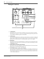
Transport Section
1 CLEAR button
This button is used to cancel the Memo 1 and Memo 2 locate points. When the Auto Punch
In/Out function is on, however, it cancels the specified punch in and punch out points. In this
case, the Memo 1 and Memo 2 points are not cancelled.
2 SYNC button
This button turns off the dbx noise reduction system for Track 8. It’s used when recording and
playing an FSK or SMPTE synchronization signal on Track 8. The SYNC indicator on the display
lights up when the SYNC function is set for FSK and flashes when it’s set for SMPTE.
3 dbx button
This button is used to turn on and off the dbx noise reduction system. The dbx indicator on the
display lights up when dbx is turned on. The dbx system is turned on automatically each time
the MT8XII is turned on.
4 AUTO PUNCH I/O button and indicator
This button is used to turn on and off the Auto Punch In/Out function. The adjacent indicator
lights up when the Auto Punch In/Out function is on.
5 TAPE SPEED control, switch, and indicators
These controls are used to adjust the tape speed. When the speed is fixed at normal, the green
FIX indicator lights up. When the speed is set to variable, the red VARI indicator lights up. The
rotary control is used to increase or decrease the tape speed, and the adjacent switch is used to
select the VARI and FIX modes.
–
0
+
TAPE SPEED REC SELECT
VARI
FIX
GROUP
AUTO
PUNCH I/O
CLEARSYNC
CHECK REPEAT
RESET
MEMO 1
MEMO 2
RTZ
LOC 1
LOC 2
FF STOPREWPLAYREHE
PHONES PUNCH I/O
REC/PAUSE
1
1
5
2
2
6
3
3
7
4
4
8
1
3
5 6
9
0
8
7
A
2
4

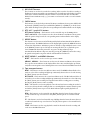
Transport Section 9
MT8XII—Owner’s Manual
6 REC SELECT buttons
These buttons are used to select tracks for recording. When a track is selected for recording, a
flashing circle appears around the corresponding track select indicator on the display. Up to four
tracks can be recorded simultaneously. You cannot record tracks that share the same REC
SELECT button simultaneously (e.g., you cannot record on tracks 1 and 5 or 3 and 7 simulta-
neously).
7 CHECK button
This button is used to check the position of the Memo 1 and Memo 2 locate points. While hold-
ing down the [CHECK] button, press and hold the [MEMO 1] or [MEMO 2] to check a locate
point. While checking a locate point, the corresponding memo indicator flashes on the display.
8 RTZ, LOC 1, and LOC 2 buttons
RTZ (Return To Zero)—This button is used to rewind the tape to the 00:00 position.
LOC 1 and LOC 2—These buttons are used to locate the Memo 1 and Memo 2 locate points.
While the point is being located, the corresponding memo indicator flashes on the display.
9 REPEAT button
This button is used to turn on and off the Repeat Playback and Auto Punch In/Out Rehearse
Repeat functions. The REPEAT indicator on the display lights up when the REPEAT function
is turned on. If the Memo 1 and Memo 2 points are already set, Repeat Playback starts as soon
as the [REPEAT] button is pressed. If only one memo point has been set, playback repeats
between 00:00 and that memo point. After 16 repeats, the Repeat function stops.
Auto Punch In/Out Rehearse Repeat is started by pressing the [REPEAT] button after setting
the punch-in and punch-out points with the Auto Punch In/Out function.
0 RESET, MEMO 1, and MEMO 2 buttons
RESET—This button is used to reset the tape counter to 00:00.
MEMO 1, MEMO 2—These button are used to store the Memo 1 and Memo 2 locate points.
The respective memo indicator on the display flashes three times and then lights up continu-
ously when a memo point is stored. Memo points are not stored when the MT8XII is turned off.
A Tape transport buttons
REHE—This button is used to enter Rehearse Pause mode. The REHE indicator flashes if no
tracks are selected for recording and lights up continuously when tracks are selected. Pressing
the [PLAY] button starts the rehearsal.
REC/PAUSE—This button is used to enter Record Pause mode. The REC indicator flashes if
no tracks are selected for recording and lights up continuously when tracks are selected. Pressing
the [PLAY] button starts recording. Pressing this button while recording pauses recording.
Pressing the [PLAY] button resumes recording.
PLAY—This button is used to start playback, start rehearsal, and start recording. It can also be
used to cancel rehearsal and recording. In this case, normal playback continues from the point
at which the [PLAY] button is pressed. The PLAY indicator lights up while playback is in
progress.
REW—This button is used to rewind the tape. Holding down the button for more than one
second rewinds the tape even faster. Press the [REW] button again to select normal rewind
speed.
FF—This button is used to fast forward the tape. Holding down the button for more than one
second fast forwards the tape even faster. Press the [FF] button again to select normal fast for-
ward speed.
STOP—This button is used to stop playback, rewind, fast forward, rehearsal, recording, and
set the meter Peak Hold function.

10 Touring the MT8XII
MT8XII—Owner’s Manual
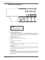
Rear Panel Connectors
1 STEREO INPUT (UNBAL) 9–14
These 1/4-inch phone jacks are used to connect electronic musical instruments and other
line-level sound sources that have stereo outputs. They can also be used to return the processed
stereo signals from external effects processors. The processed signals can then be mixed into the
MT8XII stereo mix or recorded to tracks.
2 POWER ON/OFF switch
This switch is used to turn on and off the MT8XII.
3 AC IN
Connect the supplied power cord here.
4 AUX SEND
These 1/4-inch phone jacks are used to send the Aux Send signals to external effects processors.
Connect them to the effects processors’ inputs.
5 STEREO OUT
These phono jacks are used to connect a stereo master recorder for recording the final mix. The
master recorder could be a DAT recorder, MiniDisc recorder, or cassette tape deck. Connect
them to your master recorder’s stereo inputs.
6 MONITOR OUT
These phono jacks are used to send the monitor signals to a stereo monitor amplifier and speak-
ers. This could be a dedicated monitor amplifier and speakers or your hi-fi system. Connect
them to the monitor amplifier’s stereo inputs. The MONITOR OUT signal is the same as the
headphone signal.
AC IN
POWER
ON/ OFF
14
RL
21
RL RL
13 12 11 10 9
STEREO INPUT (UNBAL)
AUX SEND
RL
STEREO OUT
RL
MONITOR OUT
2 3 456
1
CAUTION
TO PREVENT ELECTRIC SHOCK,
MATCH WIDE BLADE OF PLUG TO
WIDE SLOT, FULLY INSERT.

Rear Panel Connectors 11
MT8XII—Owner’s Manual
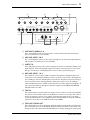
7 LINE INPUT (UNBAL) 5–8
These 1/4-inch phone jacks are used to connect electronic musical instruments and other
line-level sound sources to the MT8XII.
8 MIC/LINE INPUTs 3 & 4
These 1/4-inch phone jacks are used to connect microphones, electronic musical instruments,
and other line-level sound sources to the MT8XII.
9 INSERT I/O
These TRS phone jacks are used to connect signal processors for use with input channel 1 and
input channel 2 exclusively. Typically, compressors, limiters, and noise gates are connected to
this type of connection. A wiring diagram for an insert cable is provided on page 35.
0 MIC/LINE INPUTs 1 & 2
These inputs are used to connect balanced condenser microphones and balanced line-level
sound sources to the MT8XII. Unbalanced sources can also be connected here. Each input fea-
tures a XLR-type connector and TRS phone jack connector. The phone jack connector has pri-
ority. So you must remove any plugs from the phone jack connector to use the XLR-type
connector. Phantom power is available on these inputs for use with condenser microphones. If
you’re not using condenser microphones with these inputs, keep the PHANTOM POWER
ON/OFF switch set to OFF.
A TAPE IN
These phono jacks are used to connect the outputs of a stereo master recorder to the MT8XII.
The master recorder could be a DAT recorder, MiniDisc recorder, or cassette tape deck. Connect
them to your master recorder’s stereo outputs. To monitor the output of the stereo master
recorder during mixdown, set the TAPE IN switch to TO MONITOR. To assign the TAPE IN
signal to the stereo mix, set the TAPE IN switch to TO STEREO.
B TAPE OUT/GROUP OUT
These phono jacks are used to send the tape playback signals or group signals to another mixer.
This is useful when you use the MT8XII in conjunction with a sub mixer. Connect them to the
line inputs on the other mixer. When the MT8XII is not recording or playing, the group signals
OUT
SYNC INPUT LEVEL
IN +48V ON OFF
PHANTOM POWER
87
6
5 4 3 INSERT I/O 2 INSERT I/O 1
MIC/LINE INPUTLINE INPUT (UNBAL)
RL
TAPE IN
8765 4321
21
TAPE OUT / GROUP OUT
MIC/LINE INPUT (BAL)
1:GND
2:HOT
DC48V
MAX. 7mA
3:COLD
DC48V
MAX. 7mA
7 8 9
DA B C
0

12 Touring the MT8XII
MT8XII—Owner’s Manual
are output. Up to four group signals can be output simultaneously. A track must be selected for
recording using the [REC SELECT] buttons for the group signal to be output. Group signals 1
through 4 can be output to GROUP OUTs 1 through 4 or GROUP OUTs 5 through 8. This is
determined by the individual [REC SELECT] switches. For example, group signal 2 can be out-
put to either GROUP OUT 2 or GROUP OUT 6, using REC SELECT button [2–6].
During playback, the eight tape signals are output.
C SYNC IN/OUT & INPUT LEVEL control
These phono jacks are used to connect FSK and SMPTE synchronization signals. The INPUT
LEVEL control is used to adjust the level of the incoming SYNC signal that’s recorded onto
Track 8.
D PHANTOM POWER ON/OFF switch
This switch is used to turn on and off the phantom power for the XLR-type MIC/LINE (BAL)
inputs on channels 1 and 2. Phantom power is used to power condenser microphones. It should
be turned off when devices other than condenser microphones are connected to those inputs.
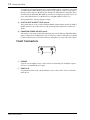
Front Connectors
1 PHONES
A pair of stereo headphones can be connected here for monitoring. The headphone signal is
the same as the MONITOR OUT signal.
2 PUNCH I/O
An optional footswitch, such as the Yamaha FC5, can be connected here for foot-controlled
punch in/out.
1
2

The First Session 13
MT8XII—Owner’s Manual
3 The First Session
This chapter explains how to record and mix your first MT8XII session. If this is your first time
with a multitrack recorder, we recommend that you start with this chapter and follow all the
procedures closely. When you’ve completed this chapter, have a look at subsequent chapters,
which explain more advanced MT8XII functions and require a basic knowledge of the MT8XII
and multitrack recording techniques.
Connecting the Power Cord
1. Connect the supplied power cord to the AC IN socket on the rear of the
MT8XII.
2. Plug the other end of the power cord into a suitable AC wall outlet.
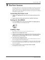
Turning On the MT8XII
1. Press the POWER switch at the rear of the MT8XII. The display lights up.
To turn off the MT8XII, press the POWER switch again.
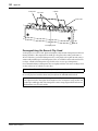
Loading a Tape
Before loading a tape, make sure the tape is not slack inside the cassette.
1. Open the cassette compartment cover.
2. Load the cassette firmly into the compartment with the tape opening facing
forward and the A side facing up. Make sure that it is seated correctly.
The TAPE indicator appears on the display.
3. Close the cassette compartment cover.
If it’s a new tape, fast forward and rewind it once to prevent binding, which may occur due to
the tape being tightly wound during manufacturing.
4. Press the [PLAY] button to start playback, and stop after about 20 seconds.
It’s best not to use the first and last 20 seconds of a tape, as the splice between the leader and
tape can cause distortion.
5. Press the [RESET] button to reset the tape counter to 00:00.
The MT8XII is now ready for recording.
POWER
ON/ OFF
Sayfa yükleniyor...
Sayfa yükleniyor...
Sayfa yükleniyor...
Sayfa yükleniyor...
Sayfa yükleniyor...
Sayfa yükleniyor...
Sayfa yükleniyor...
Sayfa yükleniyor...
Sayfa yükleniyor...
Sayfa yükleniyor...
Sayfa yükleniyor...
Sayfa yükleniyor...
Sayfa yükleniyor...
Sayfa yükleniyor...
Sayfa yükleniyor...
Sayfa yükleniyor...
Sayfa yükleniyor...
Sayfa yükleniyor...
Sayfa yükleniyor...
Sayfa yükleniyor...
Sayfa yükleniyor...
Sayfa yükleniyor...
Sayfa yükleniyor...
Sayfa yükleniyor...
Sayfa yükleniyor...
Sayfa yükleniyor...
Sayfa yükleniyor...
Sayfa yükleniyor...
Sayfa yükleniyor...
Sayfa yükleniyor...
Sayfa yükleniyor...
Sayfa yükleniyor...
Sayfa yükleniyor...
Sayfa yükleniyor...
Sayfa yükleniyor...
Sayfa yükleniyor...
Sayfa yükleniyor...
Sayfa yükleniyor...
Sayfa yükleniyor...
Sayfa yükleniyor...
Sayfa yükleniyor...
Sayfa yükleniyor...
Sayfa yükleniyor...
Sayfa yükleniyor...
Sayfa yükleniyor...
-
 1
1
-
 2
2
-
 3
3
-
 4
4
-
 5
5
-
 6
6
-
 7
7
-
 8
8
-
 9
9
-
 10
10
-
 11
11
-
 12
12
-
 13
13
-
 14
14
-
 15
15
-
 16
16
-
 17
17
-
 18
18
-
 19
19
-
 20
20
-
 21
21
-
 22
22
-
 23
23
-
 24
24
-
 25
25
-
 26
26
-
 27
27
-
 28
28
-
 29
29
-
 30
30
-
 31
31
-
 32
32
-
 33
33
-
 34
34
-
 35
35
-
 36
36
-
 37
37
-
 38
38
-
 39
39
-
 40
40
-
 41
41
-
 42
42
-
 43
43
-
 44
44
-
 45
45
-
 46
46
-
 47
47
-
 48
48
-
 49
49
-
 50
50
-
 51
51
-
 52
52
-
 53
53
-
 54
54
-
 55
55
-
 56
56
-
 57
57
-
 58
58
-
 59
59
-
 60
60
-
 61
61
-
 62
62
-
 63
63
-
 64
64
-
 65
65


Yamaha MT8X Kullanım kılavuzu
- Kategori
- Kaset çalarlar
- Tip
- Kullanım kılavuzu
diğer dillerde
- español: Yamaha MT8X Manual de usuario
- français: Yamaha MT8X Manuel utilisateur
- italiano: Yamaha MT8X Manuale utente
- svenska: Yamaha MT8X Användarmanual
- 日本語: Yamaha MT8X ユーザーマニュアル
- čeština: Yamaha MT8X Uživatelský manuál
- polski: Yamaha MT8X Instrukcja obsługi
- Deutsch: Yamaha MT8X Benutzerhandbuch
- português: Yamaha MT8X Manual do usuário
- English: Yamaha MT8X User manual
- dansk: Yamaha MT8X Brugermanual
- русский: Yamaha MT8X Руководство пользователя
- Nederlands: Yamaha MT8X Handleiding
- română: Yamaha MT8X Manual de utilizare