Hikoki DH28PD Kullanım kılavuzu
- Kategori
- Elektrikli aletler
- Tip
- Kullanım kılavuzu

Rotary Hammer
Bohrhammer
Σφυροδραπανο περιςτροφικο
Młotowiertarka
Fúrókalapács
Vrtací kladivo
Kırıcı delici
Ciocan rotopercutor
Vrtalno rušilno kladivo
Handling instructions
Bedienungsanleitung
Οδηγίες χειρισμού
Instrukcja obsługi
Kezelési utasítás
Návod k obsluze
Kullanım talimatları
Instrucţiuni de utilizare
Navodila za rokovanje
Read through carefully and understand these instructions before use.
Diese Anleitung vor Benutzung des Werkzeugs sorgfältig durchlesen und verstehen.
Διαβάστε προσεκτικά και κατανοήσετε αυτές τις οδηγίες πριν τη χρήση.
Przed użytkowaniem należy dokładnie przeczytać niniejszą instrukcję i zrozumieć jej treść.
Használat előtt olvassa el fi gyelmesen a használati utasítást.
Před použitím si pečlivě přečtěte tento návod a ujistěte se, že mu dobře rozumíte.
Aleti kullanmadan önce bu kılavuzu iyice okuyun ve talimatları anlayın.
Înainte de utilizare, citiţi cu atenţie şi înţelegeţi prezentele instrucţiuni.
Pred uporabo natančno preberite in razumite ta navodila.
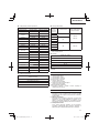
DH 28PD

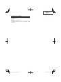
2
12
3 4
56
78

3
9 10
11 12
13 14
15 16

4
17 18
19 20
21 22
23 24

5
25 26
27 28
29 30

6
31
32

7
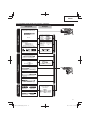
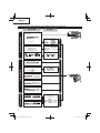
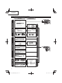
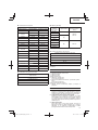
English Deutsch Ελληνικά
Drill bit Bohrer Λεπίδα τρυπανιού
Part of SDS-plus shank Teii des SDS-plus Schaftes Τμήμα του SDS-plus στελέχους
Front cap Vordere Abdeckung Μπροστινό περίβλημα
Grip Spannbacke Λαβή
Dust cup Staubschale Κύπελλο σκόνης
Dust collector (B) Staubfänger (B) Συλλέκτης σκόνης (Β)
Push button Druckschalter Κουμπί ώθησης
Change lever Wahlhebel Μοχλός αλλαγής
Push button Druckschalter Κουμπί ώθησης
Dust-collecting unit Staubfänger Μονάδα συλλογής σκόνης
Rail Strebe Οδηγός
Latch Verschluss Ασφάλεια
Nozzle Düse Ακροφύσιο
Adjuster Einstellvorrichtung Ρυθμιστής
Arrow Pfeil Βέλος
Adjuster rod Einstellstab Ράβδος ρυθμιστή
Lever Hebel Μοχλός
Dust box Staubgefäß Κουτί σκόνης
Nozzle seal Düsendichtung Εμφράκτης ακροστομίου
Rubber cap Gummikappe Ελαστικό κάλυμμα
Lip Lasche Χείλος
Groove Rille Εγκοπές
Groove between nozzle and nozzle
seal Rille zwischen Düse und Düsensitz Εγκοπές μεταξύ του ακροστομίου
και του εμφράκτη του ακροστομίου
Attachment hole Befestigungsloch Οπή προσαρμογής
Cover Abdeckung Κάλυμμα
Drill chuck Bohrfutter Σφικτήρας τρυπανιού
Chuck adapter Bohrfutteradapter Προσαρμογέας σφικτήρα
Chuck adapter (D) Bohrfutteradapter (D) Προσαρμογέας σφικτήρα (D)
Bit Bohrerspitze Λεπίδα
Socket Fassung Υποδοχή
Side handle Handgriff Πλευρική λαβή
Stopper Anschlag Στόπερ
Mounting hole Befestigungsöff nung Τρύπα στερέωσης
Wing bolt Flügelschraube Φτερωτό μπουλόνι
Tape shank adapter Kegelschaftadapter Κωνικός προσαρμογέας στελέχους
Cotter Dorn Κόφτης
Rest Aufl age Στήριγμα
Core bit Bohrkrone Κυλινδρικό κοπτικό τμήμα
Core bit shank Bohrkronenzapfen Άξονας κυλινδρικού κοπτικού
τμήματος
Thread Gewinde Σπείρωμα
Center pin Mittelstift Κεντρική περόνη
Guide plate Führungsplatte Οδηγητική πλάκα
Core bit tip Bohrkronenspitze Άκρη κυλινδρικού κοπτικού
τμήματος
Crank cover Kurbeldeckel Κάλυμμα στροφάλου

8
Polski Magyar Čeština
WiertłoFúróhegyVrták
Część chwytu SDS-plus Az SDS-plusz szár része Součást dříku SDS-plus
Przednia pokrywa Elülső kupak Přední kryt
Uchwyt Karmantyú Rukojeť
Kołnierz na pyłPorvédő sapka Prachová miska
Pojemnik na pył (B) Porgyűjtő (B) Lapač prachu (B)
Przycisk Nyomógomb Tlačítko
Dźwignia nastawcza Üzemmód váltó Přeřazovací páka
Przycisk Nyomógomb Tlačítko
Odpylacz Porgyűjtő egység Lapač prachu
Szyna Tartófém Vzpěra
Zatrzask Csappantyú Západka
Dysza Fúvóka Hubice
Regulator Szabályzó Nastavovací mechanizmus
Strzałka Nyíl Šipka
Pręt regulacji Beállító rúd Nastavovací tyč
Dźwignia Kar Páčka
Pojemnik na pyłPordoboz Prachový box
Uszczelka dyszy Fúvótömítés Těsnění trysky
Gumowa zatyczka Gumisapka Gumové víčko
Warga Perem Lem
Wyżłobienie Horony Žlábek
Wyżłobienie między dyszą a
uszczelką dyszy Horony a fúvó és a fúvótömítés között Žlábek mezi tryskou a těsněním
trysky
Otwór przyłączeniowy Csatlakozó nyílás Upevňovací otvor
Pokrywa Borító Kryt
Uchwyt wiertarski Fúrótokmány Sklíčidlo
Adaptor uchwytu Tokmány adapter Adaptér sklíčidla
Adaptor uchwytu narzędziowego (D) Tokmány adapter (D) Adaptér sklíčidla (D)
Wiertło Korona Nástroj
Gniazdo Befogópersely Objímka
Uchwyt boczny Oldalfogantyú Boční držadlo
Ogranicznik Rögzítőgomb Zarážka
Otwór mocujący Vezető lyuk Upevňovací otvor
Śruba łopatkowa Szárnyas csavar Křídlový šroub
Adaptor uchwytu stożkowego Kónuszos szár adapter Adaptér pro kuželovou stopku
SworzeńÉk Závlačka
Oparcie Alátámasztó blokk Klidová poloha
Koronka rdzeniowa Magfúró korona Okružní dutý vrták
Trzon koronki rdzeniowej Magfúró korona szára Stopka pro středový vrták
Gwint Menet Závit
Sworzeń centrujący Központosító tüske Středový vrtákbeton
Płyta wiodąca Vezetőlap Šablona
Granica zużycia Kopási határ Mez opotřebení
Pokrywa korby Hajtómű burkolata Kryt převodovky

9
Türkçe RomânăSlovenščina
Matkap ucu Burghiu Sveder
SDS-plus şank parçasıParte a trunchiului SDS- plus Del stebla SDS-plus
Ön mandren kapağıCapac frontal Sprednji pokrov
Kabza Cap de prindere Držalo
Tozluk Inel de colectare a prafului Lovilnik prahu
Toz toplayıcı (B) Colector de praf (B) Zbiralnik prahu (B)
Basma düğmesi Buton de comandăGumb
Değiştirme kolu Manetă de comutare Preklopna ročica
Basma düğmesi Buton de comandăGumb
Toz toplama ünitesi Unitate colectare praf Enota za prestrezanje prahu
Ray ŞinăVodilo
Kilit Dispozitiv de blocare Zapah
AğızAjutajŠoba
AyarlayıcıDispozitiv reglare Nastavljalo
Ok SăgeatăPuščica
Ayar çubuğuTijă reglare Drog za nastavljalo
Kol Pârghie Vzvod
Toz kutusu Cutie praf Škatla za prah
Meme contasıObturator Šobno tesnilo
Lastik kapak Manşon de protecţie Gumijasta kapa
Dudak Opritor Nastavek
Oluk Melc Utor
Meme ve meme contası arasındaki
oluk Melcul dintre duză şi obturator Utor med šobo in šobnim tesnilom
Bağlantı deliği Orificiu pentru ataşare Luknja za pritrditev
Kapak MascăPokrov
Ek Mandren MandrinăVrtalna glava
Mandren adaptörü Adaptor pentru mandrinăAdapter vrtalne glave
Mandren adaptörü (D) Adaptor pentru mandrină (D) Adapter vrtalne glave (D)
Uç Cap Nastavek
Soket Clichet Obojka
Yan kol Mâner lateral Stranski držaj
Durdurma düğmesi Opritor Zaustavljalo
Montaj deliğiGaură de prindere Pritrdilna odprtina
Kelebek başlı cıvata Bolţ fluture Krilat vijak
Konik sap adaptörü Adaptor pentru coadă conicăAdapter za konično steblo
Kama Dorn Trn
Destekler Suport Prislon
Buat ucu Burghiu găurire inelarăVrtalna krona
Buat ucu sapıPiesă antrenare burghiu Gred vrtalne glave
DişFilet Navoj
Merkez pimi Ştift centrare Centrirni zatič
Kılavuz plakasıPlacă ghidare Vodilna plošča
Yıpranma limiti Capăt burghiu găurire inelarăVrh vrtalne krone
Krank kapağıCapac în formă de cot Pokrov ročičnega mehanizma

10
Symbols
WARNING
The following show symbols
used for the machine. Be
sure that you understand
their meaning before use.
Symbole
WARNUNG
Die folgenden Symbole
werden für diese Maschine
verwendet. Achten Sie
darauf, diese vor der
Verwendung zu verstehen.
Σύμβολα
ΠΡΟΣΟΧΗ
Τα παρακάτω δείχνουν
τα σύμβολα που
χρησιμοποιούνται στο
μηχάνημα. Βεβαιωθείτε ότι
κατανοείτε τη σημασίας
τους πριν τη χρήση.
Symbole
OSTRZEŻENIE
Następujące oznaczenia
to symbole używane w
instrukcji obsługi maszyny.
Upewnij się, że rozumiesz
ich znaczenie zanim użyjesz
narzędzia.
Jelölések
FIGYELEM
Az alábbiakban a géphez
alkalmazott jelölések
vannak felsorolva. A gép
használata előtt feltétlenül
ismerje meg ezeket a
jelöléseket.
To reduce the risk of
injury, user must read
instruction manual.
Failure to follow the
warnings and instructions
may result in electric shock,
fi re and/or serious injury.
Der Anwender muss die
Bedienungsanleitung
lesen, um das Risiko
einer Verletzung zu
verringern.
Wenn die Warnungen
und Anweisungen nicht
befolgt werden, kann es
zu Stromschlag, Brand
und/oder ernsthaften
Verletzungen kommen.
Για τον περιορισμό του
κινδύνου τραυματισμού,
ο χρήστης πρέπει να
διαβάσει το εγχειρίδιο
οδηγιών χρήσης.
Η μη τήρηση των
προειδοποιήσεων και
οδηγιών μπορεί να
προκαλέσει
ηλεκτροπληξία, πυρκαγιά
και/ή σοβαρό τραυματισμό.
Aby zmniejszyć ryzyko
odniesienia obrażeń,
użytkownik powinien
przeczytać instrukcję
obsługi.
Nieprzestrzeganie
ostrzeżeń oraz wskazówek
bezpieczeństwa może
spowodować porażenie
prądem elektrycznym,
pożar i/ lub odniesienie
poważnych obrażeń.
A sérülések
kockázatának
csökkentése érdekében,
a használónak el kell
olvasnia a használati
útmutatót.
A fi gyelmeztetések
és utasítások be nem
tartása áramütést, tüzet
és/vagy súlyos sérülést
eredményezhet.
Only for EU countries
Do not dispose of electric
tools together with
household waste material!
In observance of European
Directive 2012/19/EU
on waste electrical and
electronic equipment
and its implementation in
accordance with national
law, electric tools that
have reached the end of
their life must be collected
separately and returned
to an environmentally
compatible recycling facility.
Nur für EU-Länder
Werfen Sie
Elektrowerkzeuge nicht in
den Hausmüll!
Gemäss Europäischer
Richtlinie 2012/19/EU über
Elektro- und Elektronik-
Altgeräte und Umsetzung
in nationales Recht
müssen verbrauchte
Elektrowerkzeuge
getrennt gesammelt und
einer umweltgerechten
Wiederververtung zugeführt
werden.
Μόνο για τις χώρες της EE
Μην πετάτε τα ηλεκτρικά
εργαλεία στον κάδο
οικιακών απορριμμάτων!
Σύμφωνα με την
εuρωπαϊκή οδηγία
2012/19/EE περί
ηλεκτρικών και
ηλεκτρονικών σuσκεuώv
και την ενσωμάτωσή
της στο εθνικό
δίκαιο, τα ηλεκτρικά
εργαλεία πρέπει να
σuλλέγovται ξεχωριστά
και να επιστρέφονται
για ανακύκλωση με
τρόπο φιλικό προς το
περιβάλλον.
Dotyczy tylko państw UE
Nie wyrzucaj
elektronarzędzi wraz z
odpadami z gospodarstwa
domowego!
Zgodnie z Europejską
Dyrektywą 2012/19/UE w
sprawie zużytego sprzętu
elektrotechnicznego i
elektronicznego oraz
dostosowaniem jej do
prawa krajowego, zużyte
elektronarzędzia należy
posegregować i zutylizować
w sposób przyjazny dla
środowiska.
Csak EU-országok számára
Az elektromos
kéziszerszámokat ne dobja
a háztartási szemétbe!
A használt villamos és
elektronikai készülékekről
szóló 2012/19/EU irányelv
és annak a nemzeti jogba
való átültetése szerint az
elhasznált elektromos
kéziszerszámokat
külön kell gyűjteni, és
környezetbarát módon újra
kell hasznosítani.
Symboly
UPOZORNĚNÍ
Následující text obsahuje
symboly, které jsou použity
na zařízení. Ujistěte se, že
rozumíte jejich obsahu před
tím, než začnete zařízení
používat.
Simgeler
DİKKAT
Aşağıda, bu alet için kullanılan
simgeler gösterilmiştir.
Aleti kullanmadan önce
bu simgelerin ne anlama
geldiğini anladığınızdan
emin olun.
Simboluri
AVERTISMENT
În cele ce urmează sunt
prezentate simbolurile
folosite pentru maşină.
Înainte de utilizare,
asiguraţi-vă că înţelegeţi
semnifi caţia acestora.
Simboli
OPOZORILO
V nadaljevanju so prikazani
simboli, uporabljeni pri
stroju. Pred uporabo se
prepričajte, da jih razumete.
Aby se snížilo riziko
zranění, uživatel si musí
přečíst návod k obsluze.
Nedodržení těchto varování
a pokynů může mít za
následek elektrický šok,
požár a/nebo vážné zranění.
Kullanıcı yaralanma
riskini azaltmak için
kullanım kılavuzunu
okumalıdır.
Uyarılara ve talimatlara
uyulmaması elektrik
çarpmasına, yangına ve/
veya ciddi yaralanmaya
neden olabilir.
Pentru a reduce
riscul de accidente,
utilizatorul trebuie să
citească manualul de
utilizare.
Nerespectarea
avertismentelor şi a
instrucţiunilor poate avea ca
efect producerea de şocuri
electrice, incendii şi/sau
vătămări grave.
Da ne bi prišlo do
poškodb, mora
uporabnik prebrati
navodila.
Z neupoštevanjem opozoril
in navodil tvegate električni
udar, požar in/ali resne
telesne poškodbe.
Jen pro státy EU
Elektrické nářadí
nevyhazujte do
komunálního odpadu!
Podle evropské směrnice
2012/19/EU o nakládání s
použitými elektrickými a
elektronickými zařízeními a
odpovídajících ustanovení
právních předpisů
jednotlivých zemí se
použitá elektrická nářadí
musí sbírat odděleně od
ostatního odpadu a podrobit
ekologicky šetrnému
recyklování.
Sadece AB ülkeleri için
Elektrikli el aletlerini evdeki
çöp kutusuna atmayınız!
Kullanılmış elektrikli
aletleri, elektrik ve
elektronikli eski cihazlar
hakkındaki 2012/19/AB
Avrupa yönergelerine göre
ve bu yönergeler ulusal
hukuk kurallarına göre
uyarlanarak, ayrı olarak
toplanmalı ve çevre
şartlarına uygun bir şekilde
tekrar değerlendirmeye
gönderilmelidir.
Numai pentru ţările membre
UE
Nu aruncaţi această sculă
electrică împreună cu
deşeurile menajere!
În conformitate cu Directiva
Europeană 2012/19/UE
referitoare la deşeurile
reprezentând echipamente
electrice şi electronice şi la
implementarea acesteia în
conformitate cu legislaţiile
naţionale, sculele electrice
care au ajuns la fi nalul
duratei de folosire trebuie
colectate separat şi duse
la o unitate de reciclare
compatibilă cu mediul
înconjurător.
Samo za države EU
Električnih orodij ne zavržite
skupaj z gospodinjskimi
odpadki!
V skladu z evropsko
direktivo 2012/19/EU
o odpadni električni in
elektronski opremi in izvedbi
v skladu z državnimi zakoni,
je treba električna orodja, ki
so dosegla življenjsko dobo
ločeno zbirati in vrniti v z
okoljem združljivo ustanovo
za recikliranje.

English
11
GENERAL POWER TOOL SAFETY WARNINGS
WARNING
Read all safety warnings, instructions, illustrations and
specifi cations provided with this power tool.
Failure to follow all instructions listed below may result in
electric shock, fi re and/or serious injury.
Save all warnings and instructions for future reference.
The term “power tool” in the warnings refers to your mains-
operated (corded) power tool or battery-operated (cordless)
power tool.
1) Work area safety
a) Keep work area clean and well lit.
Cluttered or dark areas invite accidents.
b) Do not operate power tools in explosive
atmospheres, such as in the presence of
fl ammable liquids, gases or dust.
Power tools create sparks which may ignite the dust
or fumes.
c) Keep children and bystanders away while
operating a power tool.
Distractions can cause you to lose control.
2) Electrical safety
a) Power tool plugs must match the outlet. Never
modify the plug in any way. Do not use any
adapter plugs with earthed (grounded) power
tools.
Unmodifi ed plugs and matching outlets will reduce
risk of electric shock.
b) Avoid body contact with earthed or grounded
surfaces, such as pipes, radiators, ranges and
refrigerators.
There is an increased risk of electric shock if your
body is earthed or grounded.
c) Do not expose power tools to rain or wet
conditions.
Water entering a power tool will increase the risk of
electric shock.
d) Do not abuse the cord. Never use the cord for
carrying, pulling or unplugging the power tool.
Keep cord away from heat, oil, sharp edges or
moving parts.
Damaged or entangled cords increase the risk of
electric shock.
e) When operating a power tool outdoors, use an
extension cord suitable for outdoor use.
Use of a cord suitable for outdoor use reduces the
risk of electric shock.
f) If operating a power tool in a damp location
is unavoidable, use a residual current device
(RCD) protected supply.
Use of an RCD reduces the risk of electric shock.
3) Personal safety
a) Stay alert, watch what you are doing and use
common sense when operating a power tool.
Do not use a power tool while you are tired
or under the infl uence of drugs, alcohol or
medication.
A moment of inattention while operating power tools
may result in serious personal injury.
b) Use personal protective equipment. Always
wear eye protection.
Protective equipment such as a dust mask, non-skid
safety shoes, hard hat or hearing protection used for
appropriate conditions will reduce personal injuries.
c) Prevent unintentional starting. Ensure the
switch is in the off -position before connecting to
power source and/or battery pack, picking up or
carrying the tool.
Carrying power tools with your fi nger on the switch or
energising power tools that have the switch on invites
accidents.
d) Remove any adjusting key or wrench before
turning the power tool on.
A wrench or a key left attached to a rotating part of the
power tool may result in personal injury.
e) Do not overreach. Keep proper footing and
balance at all times.
This enables better control of the power tool in
unexpected situations.
f) Dress properly. Do not wear loose clothing or
jewellery. Keep your hair and clothing away from
moving parts.
Loose clothes, jewellery or long hair can be caught in
moving parts.
g) If devices are provided for the connection of
dust extraction and collection facilities, ensure
these are connected and properly used.
Use of dust collection can reduce dust-related
hazards.
h) Do not let familiarity gained from frequent use
of tools allow you to become complacent and
ignore tool safety principles.
A careless action can cause severe injury within a
fraction of a second.
4) Power tool use and care
a) Do not force the power tool. Use the correct
power tool for your application.
The correct power tool will do the job better and safer
at the rate for which it was designed.
b) Do not use the power tool if the switch does not
turn it on and off .
Any power tool that cannot be controlled with the
switch is dangerous and must be repaired.
c) Disconnect the plug from the power source and/
or remove the battery pack, if detachable, from
the power tool before making any adjustments,
changing accessories, or storing power tools.
Such preventive safety measures reduce the risk of
starting the power tool accidentally.
d) Store idle power tools out of the reach of children
and do not allow persons unfamiliar with the
power tool or these instructions to operate the
power tool.
Power tools are dangerous in the hands of untrained
users.
e) Maintain power tools and accessories. Check
for misalignment or binding of moving parts,
breakage of parts and any other condition
that may aff ect the power toolʼs operation. If
damaged, have the power tool repaired before
use.
Many accidents are caused by poorly maintained
power tools.
(Original instructions)

English
12
ROTARY HAMMER SAFETY WARNINGS
Safety instructions for all operations
1. Wear ear protectors
Exposure to noise can cause hearing loss.
2. Use auxiliary handle(s), if supplied with the tool.
Loss of control can cause personal injury.
3. Hold the power tool by insulated gripping surfaces,
when performing an operation where the cutting
accessory may contact hidden wiring or its own
cord.
Cutting accessory contacting a “live” wire may make
exposed metal parts of the power tool “live” and could
give the operator an electric shock.
Safety instructions when using long drill bits with
rotary hammers
4. Always start drilling at low speed and with the bit tip
in contact with the workpiece.
At higher speeds, the bit is likely to bend if allowed to
rotate freely without contacting the workpiece, resulting
in personal injury.
5. Apply pressure only in direct line with the bit and do
not apply excessive pressure.
Bits can bend causing breakage or loss of control,
resulting in personal injury.
f) Keep cutting tools sharp and clean.
Properly maintained cutting tools with sharp cutting
edges are less likely to bind and are easier to control.
g) Use the power tool, accessories and tool bits
etc. in accordance with these instructions,
taking into account the working conditions and
the work to be performed.
Use of the power tool for operations diff erent from
those intended could result in a hazardous situation.
h) Keep handles and grasping surfaces dry, clean
and free from oil and grease.
Slippery handles and grasping surfaces do not allow
for safe handling and control of the tool in unexpected
situations.
5) Service
a) Have your power tool serviced by a qualifi ed
repair person using only identical replacement
parts.
This will ensure that the safety of the power tool is
maintained.
PRECAUTION
Keep children and infi rm persons away.
When not in use, tools should be stored out of reach of
children and infi rm persons.
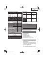
SPECIFICATIONS
Voltage (by areas)* (110 V, 115 V, 120 V, 127 V, 220 V, 230 V, 240 V)
Power Input 720 W
No-load speed 0–1050 min–1
Full-load impact rate 0–4000 min–1
Capacity: concrete
steel
wood
4–28 mm
13 mm
32 mm
Weight** 4.1 kg
Dust collecting adapter
Max. hole-drilling depth:
Diameter of drill:
Max. length of drill (eff ective length):
85 mm (adjustment possible between 0 and 85 mm)
4–18 mm
100 mm
Dust box capacity: 0.4 liters
* Be sure to check the nameplate on product as it is subject to change by areas.
** According to EPTA-Procedure 01/2014.
STANDARD ACCESSORIES
(1) Plastic case ..................................................................1
(2) Side handle ..................................................................1
(3) Stopper ........................................................................1
(4) Cover ...........................................................................1
(5) Rubber cap (replacement) ...........................................1
Standard accessories are subject to change without notice.

English
13
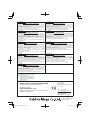
OPTIONAL ACCESSORIES (sold separately)
+
+ +
Drill bit (Taper shank)
Taper shank
adapter Cotter
Guide plate Center pin Core bit Core bit shank
● Large hole boring
● Anchor setting
Anchor setting adapter
● Bolt placing operation with
Chemical Anchor
Chemical anchor adapter
Chuck
adapter
Drill chuck
(13 VLRB-D)
Special
screw
● Demolishing operation
Dust cup Dust collector (B)
Rotation only Hammering only Rotation + Hammering
●
Drilling holes in concrete or tile
● Drilling anchor holes
● Groove digging and edging
● Grooving
● Driving screws
● Drilling in steel or wood
⊕ Driver bit ⊖ Driver bit
Drill bit for steel Drill bit for wood
Grooving chisel
Cold chisel Cutter
Hexagon socket
Bull point
(Square type) Bull point
(Round type)
Drill bit
Tool Adapters
Use on jobs facing upwards

English
14
● Drilling holes in concrete or tile
SDS-plus Drill bit
Outer dia. Overall length Eff ective length
4.0 mm 110 mm 50 mm
5.0 mm 110 mm 50 mm
160 mm 100 mm
5.5 mm 110 mm 50 mm
6.5 mm 160 mm 100 mm
7.0 mm 160 mm 100 mm
8.0 mm 160 mm 100 mm
8.5 mm 160 mm 100 mm
9.0 mm 160 mm 100 mm
12.0 mm 166 mm 100 mm
260 mm 200 mm
12.7 mm 166 mm 100 mm
14.0 mm 166 mm 100 mm
15.0 mm 166 mm 100 mm
16.0 mm 166 mm 100 mm
260 mm 200 mm
17.0 mm 166 mm 100 mm
19.0 mm 260 mm 200 mm
20.0 mm 250 mm 200 mm
22.0 mm 250 mm 200 mm
25.0 mm 450 mm 400 mm
● Drilling anchor holes
Taper shank adapter
Taper mode
Morse taper No.1
Morse taper No.2
A-Taper
B-taper
● Large hole boring
Core bit
Outer dia. Center pin Core bit shank
Overall length
25 mm* Not applicable
105 mm
300 mm
29 mm*
32 mm
(A)35 mm
38 mm
45 mm
(B) 300 mm
50 mm
65 mm
80 mm
* Without guide plate
● Anchor setting
Anchor setting adapter
Anchor size
W 1/4”
W 5/16”
W 3/8”
W 1/2”
W 5/8”
Optional accessories are subject to change without notice.
APPLICATIONS
Rotation and hammering function
○ Drilling anchor holes
○ Drilling holes in concrete
○ Drilling holes in tile
Rotation only function
○ Drilling in steel or wood
(with optional accessories)
○ Tightening machine screws, wood screws
(with optional accessories)
Hammering only function
○ Light-duty chiselling of concrete, groove digging and
edging.
PRIOR TO OPERATION
1. Power source
Ensure that the power source to be utilized conforms
to the power requirements specifi ed on the product
nameplate.
2. Power switch
Ensure that the power switch is in the OFF position. If
the plug is connected to a power receptacle while the
power switch is in the ON position, the power tool will
start operating immediately, which could cause a serious
accident.
3. Extension cord
When the work area is removed from the power source,
use an extension cord of suffi cient thickness and rated
capacity. The extension cord should be kept as short as
practicable.
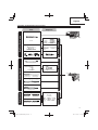
4. Mounting the drill bit (Fig. 1)
CAUTION
To prevent accidents, make sure to turn the switch off
and disconnect the plug from the receptacle.
NOTE
When using tools such as bull points, drill bits, etc.,
make sure to use the genuine parts designated by our
company.
(1) Clean the shank portion of the drill bit.
(2) Insert the drill bit in a twisting manner into the tool holder
until it latches itself. (Fig. 1)
(3) Check the latching by pulling on the drill bit.
(4) To remove the drill bit, fully pull the grip in the direction of
the arrow and pull out the drill bit. (Fig. 2)
5. Installation of dust cup or dust collector (B)
(Optional accessories) (Fig. 3, Fig. 4)
When using a rotary hammer for upward drilling
operations attach a dust cup or dust collector (B) to
collect dust or particles for easy operation.

English
15
○ Installing the dust cup
Use the dust cup by attaching to the drill bit as shown in
Fig. 3.
When using a bit which has big diameter, enlarge the
center hole of the dust cup with this rotary hammer.
○ Installing dust collector (B)
When using dust collector (B), insert dust collector (B)
from the tip of the bit by aligning it to the groove on the
grip. (Fig. 4)
CAUTION
○ The dust cup and dust collector (B) are for exclusive use
of concrete drilling work. Do not use them for wood or
metal drilling work.
○ Insert dust collector (B) completely into the chuck part of
the main unit.
○ When turning the rotary hammer on while dust collector
(B) is detached from a concrete surface, dust collector
(B) will rotate together with the drill bit. Make sure to turn
on the switch after pressing the dust cup on the concrete
surface. (When using dust collector (B) attached to
a drill bit that has more than 190 mm of overall length,
dust collector (B) cannot touch the concrete surface and
will rotate. Therefore please use dust collector (B) by
attaching to drill bits which have 166 mm, 160 mm, and
110 mm overall length.)
○ Dump particles after every two or three holes when
drilling.
○ Please replace the drill bit after removing dust collector
(B).
6. Selecting the driver bit
Screw heads or bits will be damaged unless a bit
appropriate for the screw diameter is employed to drive
in the screws.
7. Confi rm the direction of bit rotation (Fig. 5)
The bit rotates clockwise (viewed from the rear side) by
pushing the R-side of the push button. The L-side of the
push button is pushed to turn the bit counterclockwise.
8. Selecting the function mode
You can switch functions to the 3 modes of “hammering
only”, “rotation + hammering”, and “rotation only” by
turning the change lever while pressing the push button.
Set the ▲ mark position of the change lever to that of the
mode to be used.
CAUTION
○ Before operating the change lever, check and make sure
that the motor has stopped.
A failure can occur if it is operated while the motor is
running.
○ To operate the change lever, press the push button,
and release the lock of the change lever. Also, check
and make sure after operation that the push button has
returned and that the change lever has been locked.
○ Switch the change lever without mistake. If it is used at a
position halfway, there is a fear that the service life of the
switching mechanism may be shortened.
HOW TO USE
CAUTION
To prevent accidents, make sure to turn the switch off
and disconnect the plug from the receptacle when the
drill pits and other various parts are installed or removed.
The power switch should also be turned off during a work
break and after work.
NOTE
Ensure that the wing bolt in the side handle is properly
tightened before using the tool.
1. Switch operation
The rotation speed of the drill bit can be controlled
steplessly by varying the amount that the trigger switch
is pulled. Speed is low when the trigger switch is pulled
slightly and increases as the switch is pulled more.
However, the switch trigger can only be pulled in halfway
during reverse and rotates at half the speed of forward
operation.
2. Rotation + hammering
This rotary hammer can be set to rotation and hammering
mode by pressing the push button and turning the change
lever to the mark. (Fig. 6)
Turn the grip slightly and confi rm that the clutch has been
engaged with a click.
(1) Mount the drill bit.
(2) Pull the trigger switch after applying the drill bit tip to the
drilling position. (Fig. 7)
(3) Pushing the rotary hammer forcibly is not necessary at
all. Pushing slightly so that drill dust comes out gradually
is suffi cient.
CAUTION
When the drill bit touches construction iron bar, the bit
will stop immediately and the rotary hammer will react to
revolve. Therefore grip the side handle and handle tightly
as shown in Fig. 7.
3. Using the dust-collecting unit
Using the rotary hammer with the dust-collecting unit
attached creates a more hygienic working environment
free of fl ying dust (Fig. 8).
(1) Attaching the dust-collecting unit
Insert the dust-collecting unit along the rail on the rotary
hammer. When it is inserted as far as it will go, fi x it to the
rotary hammer with the two latches (Fig. 9).
CAUTION
The dust-collecting unit is designed for use when drilling
concrete. Do not use for drilling holes in metal or wood.
(2) Adjusting the dust-collecting unit
(a) Adjusting the position of the dust-collecting nozzle
Push the nozzle in and adjust to the desired position.
Pull the adjuster on the nozzle in the direction of the
arrow to release the lock and move until it contacts
with the adjuster rod. Push the adjuster in the
opposite direction to the arrow to lock (Fig. 10).
(b) Setting the hole-drilling depth
Pull the adjuster on the handle in the direction of the
arrow to release the lock, move to the desired position
to determine the stroke, and push the adjuster in the
opposite direction to the arrow to lock.
The nozzle travel distance when the tip of the nozzle
matches the tip of the drill bit is the hole-drilling depth.
(Fig. 11)
○ The maximum hole-drilling depth when using the
dust-collecting unit is 85 mm.
○ When using the dust-collecting unit, it is possible to
use HiKOKI drill bits between 4 mm and 18 mm in
diameter and up to 100 mm in eff ective length.
(3) Drilling holes
When drilling holes, hold the rotary hammer so that the
tip of the nozzle contacts with the concrete surface. Dust-
collecting eff ectiveness is reduced if the unit is not in
contact with the surface (Fig. 12).

English
16
(4) Removing dust
Excessive dust in the dust box will reduce dust-collecting
eff ectiveness. Empty the dust box regularly.
Push the lever to remove the dust box from the dust-
collecting unit, and empty and clean the box (Fig. 13).
Dust-collecting eff ectiveness is reduced if the fi lter in the
dust box becomes blocked.
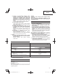
Use the table below as a guide to replacement of the dust
box.
Dust box capacity Drill diameter of 6 mm / depth of 28 mm: 130 holes
Drill diameter of 8 mm / depth of 30 mm: 75 holes
Drill diameter of 12 mm / depth of 50 mm: 20 holes
Guide to replacement of dust box Dust box has been fi lled and emptied 100 times
(5) Replacing the rubber cap
Wear of the rubber cap will reduce dust-collecting
eff ectiveness.
Replace the rubber cap when it becomes worn.
How to replace the rubber cap (Fig. 14)
(1) Remove the nozzle seal from the nozzle.
(2) Replace the rubber cap with a new cap.
Fit the rubber cap making sure that it is correctly oriented.
(3) Attach the nozzle seal.
Insert the lip of the nozzle seal securely into the groove of
the nozzle.
At this time, make sure that the groove between the
nozzle and the nozzle seal is uniform all the way round.
4. When not using the dust-collecting unit
When using the rotary hammer without the dust-collecting
unit, attach the provided cover in the unit attachment hole
(Fig. 15).
CAUTION
If no cover is attached, dust or other particles may be
sucked up from the hole, causing damage to the motor.
5. Rotation only
NOTE
The dust-collecting unit cannot be used. Remove the unit
and attach the provided cover in the unit attachment hole.
CAUTION
If no cover is attached, dust or other particles may be
sucked up from the hole, causing damage to the motor.
This rotary hammer can be set to rotation only mode by
pressing the push button and turning the change lever to
the mark. (Fig. 16)
Turn the grip slightly and confi rm that the clutch has been
engaged with a click.
To drill wood or metal material using the drill chuck
and chuck adapter (optional accessories), proceed as
follows.
Installing drill chuck and chuck adapter: (Fig. 17)
(1) Attach the drill chuck to the chuck adapter.
(2) The part of the SDS-plus shank is the same as the drill
bit. Therefore, refer to the item of “Mounting the drill bit”
for attaching it.
CAUTION
○ Application of force more than necessary will not only
expedite the work, but will deteriorate the tip edge of the
drill bit and reduce the service life of the rotary hammer in
addition.
○ Drill bits may snap off while withdrawing the rotary
hammer from the drilled hole. For withdrawing, it is
important to use a pushing motion.
○ Do not attempt to drill anchor holes or holes in concrete
with the machine set in the rotation only function.
○ Do not attempt to use the rotary hammer in the rotation
and hammering function with the drill chuck and chuck
adapter attached. This would seriously shorten the
service life of every component of the machine.
6. When driving machine screws (Fig. 18)
First, insert the bit into the socket in the end of chuck
adapter (D).
Next, mount chuck adapter (D) on the main unit using
procedures described in 4 (1), (2), (3), put the tip of the
bit in the slots in the head of the screw, grasp the main
unit and tighten the screw.
CAUTION
○ Exercise care not to excessively prolong driving time,
otherwise, the screws may be damaged by excessive
force.
○ Apply the rotary hammer perpendicularly to the screw
head when driving the screw; otherwise, the screw head
or bit will be damaged, or driving force will not be fully
transferred to the screw.
○ Do not attempt to use the rotary hammer in the rotation
and hammering function with the chuck adapter and bit
attached.
7. When driving wood screws (Fig. 18)
(1) Selecting a suitable driver bit
Employ plus-head screws, if possible, since the driver bit
easily slips off the heads of minus-head screws.
(2) Driving in wood screws
○ Prior to driving in wood screws, make pilot holes suitable
for them in the wooden board. Apply the bit to the screw
head grooves and gently drive the screws into the holes.
○ After rotating the rotary hammer at low speed for a while
until the wood screw is partly driven into the wood,
squeeze the trigger more strongly to obtain the optimum
driving force.
CAUTION
Exercise care in preparing a pilot hole suitable for
the wood screw taking the hardness of the wood into
consideration. Should the hole be excessively small or
shallow, requiring much power to drive the screw into
it, the thread of the wood screw may sometimes be
damaged.
8. Hammering only
NOTE
The dust-collecting unit cannot be used. Remove the unit
and attach the provided cover in the unit attachment hole.
CAUTION
If no cover is attached, dust or other particles may be
sucked up from the hole, causing damage to the motor.
This rotary hammer can be set to hammering only mode
by pressing the push button and turning the change lever
to the mark (Fig. 19).

English
17
(1) Mount the bull point or cold chisel.
(2) Press the push button and set the change lever to
mark. (Fig. 20)
The rotation is released, turn the tool and adjust the tool
to desired position. (Fig. 21)
(3) Turn the change lever to mark. (Fig. 19)
Then bull point or cold chisel is locked.
9. Using the stopper (Fig. 22)
(1) Loosen the wing bolt and insert the stopper into the
mounting hole on the side handle.
(2) Adjust the stopper position according to the depth of the
hole and tighten the wing bolt securely.
10. How to use the drill bit (taper shank) and the taper
shank adapter
(1) Mount the taper shank adapter to the rotary hammer.
(Fig. 23)
(2) Mount the drill bit (taper shank) to the taper shank
adapter. (Fig. 23)
(3) Turn the switch ON, and drill a hole in prescribed depth.
(4) To remove the drill bit (taper shank), insert the cotter into
the slot of the taper shank adapter and strike the head of
the cotter with a hammer supporting on a rests. (Fig. 24)
11. Make sure to securely hold the tool as shown in
Fig. 31 during operation.
12. Using the side handle
When you wish to change a position of the side handle,
turn grip of the side handle counterclockwise to loosen it,
and then fasten it fi rmly. (Fig. 32)
CAUTION
When boring a hole, there can be a case where the
machine attempts to rotate by the reaction at the time of
penetrating a concrete wall and/or when a tip of the blade
comes in contact with the rebar.
Firmly fasten the side handle and hold the machine
with both of your hands. Unless you hold it securely, an
accident can occur.
HOW TO USE THE CORE BIT
(FOR LIGHT LOAD)
When boring penerating large holes use the core bit (for light
loads). At that time use with the center pin and the core bit
shank provided as optional accessories.
1. Mounting
CAUTION
Be sure to turn power OFF and disconnect the plug from
the receptacle.
(1) Mount the core bit to the core bit shank (Fig. 25).
Lubricate the thread of the core bit shank to facilitate
disassembly.
(2) Mount the core bit to the rotary hammer (Fig. 26).
(3) Insert the center pin into the guide plate until it stops.
(4) Engage the guide plate with the core bit, and turn the
guide plate to the left or the right so that it does not fall
even if it faces downward (Fig. 27).
2. How to bore (Fig. 28)
(1) Connect the plug to the power source.
(2) A spring is installed in the center pin.
Push it lightly to the wall or the fl oor straight.
Connect the core bit tip fl ush to the surface and start
operating.
(3) When boring about 5 mm in depth the position of the hole
will be established. Bore after that removing the center
pin and the guide plate from core bit.
(4) Application of excessive force will not only expedite
the work, but will deteriorate the tip edge of the drill bit,
resulting in reduced service life of the rotary hammer.
CAUTION
When removing the center pin and the guide plate,
turn OFF the switch and disconnect the plug from the
receptacle.
3. Dismounting (Fig. 29)
Remove the core bit shank from the rotary hammer and
strike the head of the core bit shank strongly two or three
times with a hammer holding the core bit, then the thread
becomes loose and the core bit can be removed.
GREASE REPLACEMENT
This Rotary Hammer is of full air-tight construction to protect
against dust. This machine can be used without grease
replenishment for an extended period of time. However,
perform the grease replacement to extend the service life.
Replace the grease as described below.
1. Grease Replacement Period
You should look at the grease when you change the
carbon brush. (See item 4 in the section MAINTENANCE
AND INSPECTION.)
Ask for grease replacement at the nearest authorized
HiKOKI Service Center.
In the case that you are forced to change the grease by
yourself, please follow the following points.
2. How to replace grease
CAUTION
Before replacing the grease, turn the power off and pull
out the plug from the receptacle.
(1) Disassemble the crank cover and thoroughly wipe off the
old grease inside. (Fig. 30)
(2) Supply 25 g of HiKOKI Electric Hammer Grease A
(standard accessory, contained in tube) in the crank
case.
(3) After replacing the grease, reassemble the crank cover
securely. At this time, do not damage or lose the oil seal.
NOTE
The HiKOKI Electric Hammer Grease A is of the
low viscosity type. When the grease is consumed,
purchase from the authorized HiKOKI Service
Center.
MAINTENANCE AND INSPECTION
1. Inspecting the drill bits
Since use of a dull tool will cause motor malfunctioning
and degraded effi ciency, replace the drill bit with new
ones or resharpen them without delay when abrasion is
noted.
2. Inspecting the mounting screws
Regularly inspect all mounting screws and ensure that
they are properly tightened. Should any of the screws be
loose, retighten them immediately. Failure to do so could
result in serious hazard.
3. Maintenance of the motor
The motor unit winding is the very ”heart” of the power
tool. Exercise due care to ensure the winding does not
become damaged and/or wet with oil or water.
4. Inspecting the carbon brushes
For your continued safety and electrical shock protection,
carbon brush inspection and replacement on this tool
should ONLY be performed by a HiKOKI Authorized
Service Center.

English
18
5. Replacing supply cord
If the replacement of the supply cord is necessary, it has
to be done by HiKOKI Authorized Service Center to avoid
a safety hazard.
CAUTION
In the operation and maintenance of power tools, the
safety regulations and standards prescribed in each
country must be observed.
GUARANTEE
We guarantee HiKOKI Power Tools in accordance with
statutory/country specifi c regulation. This guarantee does
not cover defects or damage due to misuse, abuse, or normal
wear and tear. In case of complaint, please send the Power
Tool, undismantled, with the GUARANTEE CERTIFICATE
found at the end of this Handling instruction, to a HiKOKI
Authorized Service Center.
NOTE
Due to HiKOKI’s continuing program of research and
development, the specifi cations herein are subject to change
without prior notice.
Information concerning airborne noise and vibration
The measured values were determined according to
EN62841 and declared in accordance with ISO 4871.
Measured A-weighted sound power level: 102 dB (A).
Measured A-weighted sound pressure level: 91 dB (A).
Uncertainty KpA: 3 dB (A).
Wear ear protection.
Vibration total values (triax vector sum) determined
according to EN62841.
Hammer drilling into concrete:
Vibration emission value ah, HD = 15.9 m/s2
Uncertainty K = 2.5 m/s2 (A)
Equivalent chiselling value:
Vibration emission value ah, CHeq = 14.3 m/s2
Uncertainty K = 2.0 m/s2 (A)
The declared vibration total value and the declared noise
emission value have been measured in accordance with a
standard test method and may be used for comparing one
tool with another.
They may also be used in a preliminary assessment of
exposure.
WARNING
○ The vibration and noise emission during actual use
of the power tool can diff er from the declared total
value depending on the ways in which the tool is used
especially what kind of workpiece is processed; and
○ Identify safety measures to protect the operator that
are based on an estimation of exposure in the actual
conditions of use (taking account of all parts of the
operating cycle such as the times when the tool is
switched off and when it is running idle in addition to the
trigger time).

Deutsch
19
ALLGEMEINE SICHERHEITSHINWEISE FÜR
ELEKTROGERÄTE
WARNUNG
Bitte beachten Sie sämtliche mit diesem Elektrogerät
gelieferten Sicherheitshinweise, Anweisungen,
Illustrationen und technischen Angaben.
Wenn die nachfolgenden Anweisungen nicht befolgt werden,
kann es zu Stromschlag, Brand und/oder ernsthaften
Verletzungen kommen.
Bitte bewahren Sie alle Warnhinweise und Anweisungen
zum späteren Nachschlagen auf.
Der Begriff „Elektrowerkzeug“ bezieht sich in den
Warnhinweisen auf Elektrowerkzeuge mit Netz-
(schnurgebunden) oder Akkubetrieb (schnurlos).
1) Sicherheit im Arbeitsbereich
a) Sorgen Sie für einen sauberen und gut
ausgeleuchteten Arbeitsbereich.
Zugestellte oder dunkle Bereiche ziehen Unfälle
förmlich an.
b) Verwenden Sie Elektrowerkzeuge niemals an
Orten, an denen Explosionsgefahr besteht,
wie zum Beispiel in der Nähe von leicht
entfl ammbaren Flüssigkeiten, Gasen oder
Stäuben.
Bei der Arbeit mit Elektrowerkzeugen kann es zu
Funkenbildung kommen, wodurch sich Stäube oder
Dämpfe entzünden können.
c) Sorgen Sie bei der Arbeit mit Elektrowerkzeugen
dafür, dass sich keine Zuschauer (insbesondere
Kinder) in der Nähe befi nden.
Wenn Sie abgelenkt werden, können Sie die
Kontrolle über das Werkzeug verlieren.
2) Elektrische Sicherheit
a) Elektrowerkzeuge müssen mit passender
Stromversorgung betrieben werden. Nehmen
Sie niemals irgendwelche Änderungen am
Anschlussstecker vor. Verwenden Sie bei
Elektrowerkzeugen mit Schutzkontakt (geerdet)
niemals Adapterstecker.
Stecker im Originalzustand und passende
Steckdosen reduzieren das Stromschlagrisiko.
b) Vermeiden Sie Körperkontakt mit geerdeten
Gegenständen wie Rohrleitungen, Heizungen,
Herden oder Kühlschränken.
Bei Körperkontakt mit geerdeten Gegenständen
besteht ein erhöhtes Stromschlagrisiko.
c) Setzen Sie Elektrowerkzeuge niemals Regen
oder sonstiger Feuchtigkeit aus.
Wenn Flüssigkeiten in ein Elektrowerkzeug
eindringen, erhöht sich das Stromschlagrisiko.
d) Verwenden Sie das Anschlusskabel nicht
missbräuchlich. Tragen Sie das Elektrowerkzeug
niemals am Stromkabel, ziehen Sie es nicht
damit heran und ziehen Sie den Stecker nicht
am Anschlusskabel aus der Steckdose.
Halten Sie das Anschlusskabel von Hitzequellen,
Öl, scharfen Kanten und beweglichen Teilen
fern.
Beschädigte oder verdrehte Anschlusskabel erhöhen
das Stromschlagrisiko.
e) Verwenden Sie, wenn Sie ein Elektrowerkzeug
im Freien benutzen, ein für den Außeneinsatz
geeignetes Verlängerungskabel.
Ein für den Außeneinsatz geeignetes Kabel
vermindert das Stromschlagrisiko.
f) Falls sich der Betrieb des Elektrowerkzeugs
in feuchter Umgebung nicht vermeiden lässt,
verwenden Sie eine Stromversorgung mit
Fehlerstromschutzeinrichtung (Residual
Current Device, RCD).
Durch den Einsatz einer Fehlerstromschutzeinrichtung
wird das Risiko eines elektrischen Schlages
reduziert.
3) Persönliche Sicherheit
a) Bleiben Sie wachsam, achten Sie auf das, was
Sie tun, und setzen Sie Ihren Verstand ein, wenn
Sie mit Elektrowerkzeugen arbeiten.
Benutzen Sie keine Elektrowerkzeuge, wenn
Sie müde sind oder unter Einfl uss von Drogen,
Alkohol oder Medikamenten stehen.
Bei der Arbeit mit Elektrowerkzeugen können bereits
kurze Phasen der Unaufmerksamkeit zu schweren
Verletzungen führen.
b) Benutzen Sie eine persönliche
Schutzausrüstung. Tragen Sie immer einen
Augenschutz.
Schutzausrüstung wie Staubmaske, rutschfeste
Sicherheitsschuhe, Schutzhelm und Gehörschutz
senken bei angemessenem Einsatz das
Verletzungsrisiko.
c) Vermeiden Sie unbeabsichtigtes Einschalten.
Achten Sie darauf, dass sich der Schalter
in der Aus- (Off -) Position befi ndet, ehe Sie
das Gerät mit der Stromversorgung und/
oder Batteriestromversorgung verbinden, es
aufheben oder herumtragen.
Das Herumtragen von Elektrowerkzeugen mit
dem Finger am Schalter oder das Herstellen der
Stromversorgung bei betätigtem Schalter zieht
Unfälle regelrecht an.
d) Entfernen Sie sämtliche Einstellwerkzeuge
(Einstellschlüssel), ehe Sie das Elektrowerkzeug
einschalten.
Ein an einem beweglichen Teil des Elektrowerkzeugs
angebrachter Schlüssel kann zu Verletzungen
führen.
e) Überstrecken Sie sich nicht. Achten Sie jederzeit
darauf, sicher zu stehen und das Gleichgewicht
zu bewahren.
Dadurch haben Sie das Elektrowerkzeug in
unerwarteten Situationen besser im Griff .
f) Tragen Sie geeignete Kleidung. Tragen Sie keine
lose Kleidung oder Schmuck. Halten Sie Ihr Haar
und Ihre Kleidung von beweglichen Teilen fern.
Lose Kleidung, Schmuck oder langes Haar kann von
beweglichen Teilen erfasst werden.
g) Wenn Anschlüsse für Staubabsaug- und -
sammelvorrichtungen vorhanden sind, sorgen
Sie dafür, dass diese richtig angeschlossen und
eingesetzt werden.
Durch Entfernen des Staubes können staubbezogene
Gefahren vermindert werden.
(Übersetzung der Original-Gebrauchsanweisung)

Deutsch
20
h) Lassen Sie es nicht zu, dass die durch häufi gen
Gebrauch von Werkzeugen erworbene
Vertrautheit Sie nachlässig macht und Sie
die Sicherheitsrichtlinien für das Werkzeug
ignorieren.
Eine unvorsichtige Handlung kann in
Sekundenbruchteilen zu schweren Verletzungen
führen.
4) Einsatz und Pfl ege von Elektrowerkzeugen
a) Überbeanspruchen Sie Elektrowerkzeuge nicht.
Benutzen Sie das richtige Elektrowerkzeug für
Ihren Einsatzzweck.
Das richtige Elektrowerkzeug erledigt seine Arbeit bei
bestimmungsgemäßem Einsatz besser und sicherer.
b) Benutzen Sie das Elektrowerkzeug nicht, wenn
es sich nicht am Schalter ein- und ausschalten
lässt.
Jedes Elektrowerkzeug, das nicht mit dem Schalter
betätigt werden kann, stellt eine Gefahr dar und muss
repariert werden.
c) Ziehen Sie den Stecker der Stromversorgung
ab und/oder entfernen Sie den Akkupack
vom Elektrowerkzeug, falls abnehmbar, ehe
Sie Einstellarbeiten vornehmen, Zubehörteile
tauschen oder das Elektrowerkzeug verstauen.
Solche präventiven Sicherheitsmaßnahmen
verhindern den unbeabsichtigten Anlauf des
Elektrowerkzeugs und die damit verbundenen
Gefahren.
d) Lagern Sie nicht benutzte Elektrowerkzeuge
außerhalb der Reichweite von Kindern, lassen
Sie nicht zu, dass Personen das Elektrowerkzeug
bedienen, die nicht mit dem Werkzeug selbst
und/oder diesen Anweisungen vertraut sind.
Elektrowerkzeuge in ungeschulten Händen sind
gefährlich.
e) Wartung von Elektrowerkzeugen und Zubehör.
Prüfen Sie sie auf Fehlausrichtungen,
Leichtgängigkeit beweglicher Teile,
Beschädigungen von Teilen und auf alle
anderen Umstände, die sich auf den Betrieb des
Elektrowerkzeugs auswirken können. Lassen
Sie das Elektrowerkzeug bei Beschädigungen
reparieren, ehe Sie es benutzen.
Viele Unfälle mit Elektrowerkzeugen sind auf
schlechte Wartung zurückzuführen.
f) Halten Sie Schneidwerkzeuge scharf und
sauber.
Richtig gewartete Schneidwerkzeuge mit scharfen
Schneiden bleiben weniger häufi g hängen und sind
einfacher zu beherrschen.
g) Benutzen Sie Elektrowerkzeuge, Zubehör,
Werkzeugspitzen und Ähnliches in
Übereinstimmung mit diesen Anweisungen
– beachten Sie dabei die jeweiligen
Arbeitsbedingungen und die Art der
auszuführenden Arbeiten.
Der Gebrauch des Elektrowerkzeugs für andere
als die vorgesehenen Anwendungen kann zu
gefährlichen Situationen führen.
h) Halten Sie Handgriff e und Greiffl ächen trocken,
sauber und frei von Öl und Fett.
Rutschige Handgriff e und Greiffl ächen lassen keine
sichere Handhabung und Kontrolle des Werkzeugs
in unerwarteten Situationen zu.
5) Service
a) Lassen Sie Elektrowerkzeuge durch qualifi zierte
Fachkräfte und nur unter Einsatz passender
Originalersatzteile warten.
Dies sorgt dafür, dass die Sicherheit des
Elektrowerkzeugs nicht beeinträchtigt wird.
VORSICHT
Von Kindern und gebrechlichen Personen fernhalten.
Werkzeuge sollten bei Nichtgebrauch außerhalb der
Reichweite von Kindern und gebrechlichen Personen
aufbewahrt werden.
SICHERHEITSHINWEISE FÜR DEN
BOHRHAMMER
Allgemeine Sicherheitshinweise
1. Gehörschutz tragen
Die Aussetzung zu lauten Geräuschen kann zu
Gehörverlust führen.
2. Benutzen Sie, falls mit dem Werkzeug mitgeliefert,
den/die Hilfsgriff (e).
Ein Verlust der Kontrolle kann zu Körperverletzungen
führen.
3. Halten Sie das Elektrowerkzeug bei Arbeiten,
bei denen das Schneidezubehör verborgene
Stromleitungen berühren könnte, nur an den
isolierten Griff -Flächen.
Schneidezubehör, das eine Strom führende Leitung
berührt, kann nackte Metallteile des Elektrogeräts unter
Strom setzen und dem Bediener einen Stromschlag
versetzen.
Sicherheitshinweise zur Verwendung langer
Bohraufsätze mit Bohrhammern
4. Beginnen Sie beim Bohren immer mit niedriger
Drehzahl und so, dass die Spitze des Bits das
Werkstück berührt.
Bei höheren Drehzahlen kann sich das Bit verbiegen,
wenn es sich frei und ohne Kontakt mit dem Werkstück
dreht, was zu einer Verletzung führen kann.
5. Üben Sie Druck nur gerade entlang des Bits aus und
vermeiden Sie übermäßigen Druck.
Die Bits könnten sich verbiegen und brechen oder zu
Kontrollverlust und Verletzungen führen.
Sayfa yükleniyor...
Sayfa yükleniyor...
Sayfa yükleniyor...
Sayfa yükleniyor...
Sayfa yükleniyor...
Sayfa yükleniyor...
Sayfa yükleniyor...
Sayfa yükleniyor...
Sayfa yükleniyor...
Sayfa yükleniyor...
Sayfa yükleniyor...
Sayfa yükleniyor...
Sayfa yükleniyor...
Sayfa yükleniyor...
Sayfa yükleniyor...
Sayfa yükleniyor...
Sayfa yükleniyor...
Sayfa yükleniyor...
Sayfa yükleniyor...
Sayfa yükleniyor...
Sayfa yükleniyor...
Sayfa yükleniyor...
Sayfa yükleniyor...
Sayfa yükleniyor...
Sayfa yükleniyor...
Sayfa yükleniyor...
Sayfa yükleniyor...
Sayfa yükleniyor...
Sayfa yükleniyor...
Sayfa yükleniyor...
Sayfa yükleniyor...
Sayfa yükleniyor...
Sayfa yükleniyor...
Sayfa yükleniyor...
Sayfa yükleniyor...
Sayfa yükleniyor...
Sayfa yükleniyor...
Sayfa yükleniyor...
Sayfa yükleniyor...
Sayfa yükleniyor...
Sayfa yükleniyor...
Sayfa yükleniyor...
Sayfa yükleniyor...
Sayfa yükleniyor...
Sayfa yükleniyor...
Sayfa yükleniyor...
Sayfa yükleniyor...
Sayfa yükleniyor...
Sayfa yükleniyor...
Sayfa yükleniyor...
Sayfa yükleniyor...
Sayfa yükleniyor...
Sayfa yükleniyor...
Sayfa yükleniyor...
Sayfa yükleniyor...
Sayfa yükleniyor...
Sayfa yükleniyor...
Sayfa yükleniyor...
Sayfa yükleniyor...
Sayfa yükleniyor...
Sayfa yükleniyor...
Sayfa yükleniyor...
Sayfa yükleniyor...
Sayfa yükleniyor...
Sayfa yükleniyor...
Sayfa yükleniyor...
Sayfa yükleniyor...
Sayfa yükleniyor...
Sayfa yükleniyor...
Sayfa yükleniyor...
Sayfa yükleniyor...
Sayfa yükleniyor...
-
 1
1
-
 2
2
-
 3
3
-
 4
4
-
 5
5
-
 6
6
-
 7
7
-
 8
8
-
 9
9
-
 10
10
-
 11
11
-
 12
12
-
 13
13
-
 14
14
-
 15
15
-
 16
16
-
 17
17
-
 18
18
-
 19
19
-
 20
20
-
 21
21
-
 22
22
-
 23
23
-
 24
24
-
 25
25
-
 26
26
-
 27
27
-
 28
28
-
 29
29
-
 30
30
-
 31
31
-
 32
32
-
 33
33
-
 34
34
-
 35
35
-
 36
36
-
 37
37
-
 38
38
-
 39
39
-
 40
40
-
 41
41
-
 42
42
-
 43
43
-
 44
44
-
 45
45
-
 46
46
-
 47
47
-
 48
48
-
 49
49
-
 50
50
-
 51
51
-
 52
52
-
 53
53
-
 54
54
-
 55
55
-
 56
56
-
 57
57
-
 58
58
-
 59
59
-
 60
60
-
 61
61
-
 62
62
-
 63
63
-
 64
64
-
 65
65
-
 66
66
-
 67
67
-
 68
68
-
 69
69
-
 70
70
-
 71
71
-
 72
72
-
 73
73
-
 74
74
-
 75
75
-
 76
76
-
 77
77
-
 78
78
-
 79
79
-
 80
80
-
 81
81
-
 82
82
-
 83
83
-
 84
84
-
 85
85
-
 86
86
-
 87
87
-
 88
88
-
 89
89
-
 90
90
-
 91
91
-
 92
92


Hikoki DH28PD Kullanım kılavuzu
- Kategori
- Elektrikli aletler
- Tip
- Kullanım kılavuzu
diğer dillerde
- slovenčina: Hikoki DH28PD Používateľská príručka
- polski: Hikoki DH28PD Instrukcja obsługi
- română: Hikoki DH28PD Manual de utilizare
İlgili makaleler
Diğer belgeler
-
Hitachi DH 28PC Handling Instructions Manual
-
Hitachi DH 28PBY Handling Instructions Manual
-
Makita HR1840 Rotary Hammer Kullanım kılavuzu
-
Makita HR3011FC Kullanım kılavuzu
-
-
-
-
-