Yamaha RX-V1800 El kitabı
- Kategori
- AV alıcıları
- Tip
- El kitabı
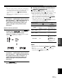
Bu kılavuz aynı zamanda aşağıdakiler için de uygundur:

YAMAHA ELECTRONICS CORPORATION, USA
6660 ORANGETHORPE AVE., BUENA PARK, CALIF. 90620, U.S.A.
YAMAHA CANADA MUSIC LTD.
135 MILNER AVE., SCARBOROUGH, ONTARIO M1S 3R1, CANADA
YAMAHA ELECTRONIK EUROPA G.m.b.H.
SIEMENSSTR. 22-34, 25462 RELLINGEN BEI HAMBURG, GERMANY
YAMAHA ELECTRONIQUE FRANCE S.A.
RUE AMBROISE CROIZAT BP70 CROISSY-BEAUBOURG 77312 MARNE-LA-VALLEE CEDEX02, FRANCE
YAMAHA ELECTRONICS (UK) LTD.
YAMAHA HOUSE, 200 RICKMANSWORTH ROAD WATFORD, HERTS WD18 7GQ, ENGLAND
YAMAHA SCANDINAVIA A.B.
J A WETTERGRENS GATA 1, BOX 30053, 400 43 VÄSTRA FRÖLUNDA, SWEDEN
YAMAHA MUSIC AUSTRALIA PTY, LTD.
17-33 MARKET ST., SOUTH MELBOURNE, 3205 VIC., AUSTRALIA
©
2007 All rights reserved.
RX-V1800
Printed in Malaysia WK69280-1
RX-V1800
AV R e c e i ve r
OWNER’S MANUAL
U
RX-V1800_U-cv.fm Page 1 Friday, June 15, 2007 4:43 PM

Caution-i En
• Explanation of Graphical Symbols
The lightning flash with arrowhead symbol, within an
equilateral triangle, is intended to alert you to the
presence of uninsulated “dangerous voltage” within
the product’s enclosure that may be of sufficient
magnitude to constitute a risk of electric shock to
persons.
The exclamation point within an equilateral triangle
is intended to alert you to the presence of important
operating and maintenance (servicing) instructions in
the literature accompanying the appliance.
1 Read Instructions – All the safety and operating instructions
should be read before the product is operated.
2 Retain Instructions – The safety and operating instructions
should be retained for future reference.
3 Heed Warnings – All warnings on the product and in the
operating instructions should be adhered to.
4 Follow Instructions – All operating and use instructions
should be followed.
5 Cleaning – Unplug this product from the wall outlet before
cleaning. Do not use liquid cleaners or aerosol cleaners.
6 Attachments – Do not use attachments not recommended by
the product manufacturer as they may cause hazards.
7 Water and Moisture – Do not use this product near water –
for example, near a bath tub, wash bowl, kitchen sink, or
laundry tub; in a wet basement; or near a swimming pool;
and the like.
8 Accessories – Do not place this product on an unstable cart,
stand, tripod, bracket, or table. The product may fall,
causing serious injury to a child or adult, and serious
damage to the product. Use only with a cart, stand, tripod,
bracket, or table recommended by the manufacturer, or sold
with the product. Any mounting of the product should
follow the manufacturer’s instructions, and should use a
mounting accessory recommended by the manufacturer.
9 A product and cart combination should be moved with care.
Quick stops, excessive force, and uneven surfaces may
cause the product and cart combination to
overturn.
10 Ventilation – Slots and openings in the cabinet are provided
for ventilation and to ensure reliable operation of the
product and to protect it from overheating, and these
openings must not be blocked or covered. The openings
should never be blocked by placing the product on a bed,
sofa, rug, or other similar surface. This product should not
be placed in a built-in installation such as a bookcase or rack
unless proper ventilation is provided or the manufacturer’s
instructions have been adhered to.
11 Power Sources – This product should be operated only from
the type of power source indicated on the marking label. If
you are not sure of the type of power supply to your home,
consult your product dealer or local power company. For
products intended to operate from battery power, or other
sources, refer to the operating instructions.
12 Grounding or Polarization – This product may be equipped
with a polarized alternating current line plug (a plug having
one blade wider than the other). This plug will fit into the
power outlet only one way. This is a safety feature. If you
are unable to insert the plug fully into the outlet, try
reversing the plug. If the plug should still fail to fit, contact
your electrician to replace your obsolete outlet. Do not
defeat the safety purpose of the polarized plug.
13 Power-Cord Protection – Power-supply cords should be
routed so that they are not likely to be walked on or pinched
by items placed upon or against them, paying particular
attention to cords at plugs, convenience receptacles, and the
point where they exit from the product.
14 Lightning – For added protection for this product during a
lightning storm, or when it is left unattended and unused for
long periods of time, unplug it from the wall outlet and
disconnect the antenna or cable system. This will prevent
damage to the product due to lightning and power-line
surges.
15 Power Lines – An outside antenna system should not be
located in the vicinity of overhead power lines or other
electric light or power circuits, or where it can fall into such
power lines or circuits. When installing an outside antenna
system, extreme care should be taken to keep from touching
such power lines or circuits as contact with them might be
fatal.
16 Overloading – Do not overload wall outlets, extension
cords, or integral convenience receptacles as this can result
in a risk of fire or electric shock.
17 Object and Liquid Entry – Never push objects of any kind
into this product through openings as they may touch
dangerous voltage points or short-out parts that could result
in a fire or electric shock. Never spill liquid of any kind on
the product.
18 Servicing – Do not attempt to service this product yourself
as opening or removing covers may expose you to
dangerous voltage or other hazards. Refer all servicing to
qualified service personnel.
19 Damage Requiring Service – Unplug this product from the
wall outlet and refer servicing to qualified service personnel
under the following conditions:
a) When the power-supply cord or plug is damaged,
b) If liquid has been spilled, or objects have fallen into the
product,
c) If the product has been exposed to rain or water,
Important safety instructions
CAUTION
CAUTION: TO REDUCE THE RISK OF
ELECTRIC SHOCK, DO NOT REMOVE
COVER (OR BACK). NO USER-SERVICEABLE
PARTS INSIDE. REFER SERVICING TO
QUALIFIED SERVICE PERSONNEL.
RISK OF ELECTRIC SHOCK
DO NOT OPEN

Important safety instructions
Caution-ii En
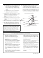
EXAMPLE OF ANTENNA GROUNDING
MAST
GROUND
CLAMP
ANTENNA
LEAD IN
WIRE
ANTENNA
DISCHARGE UNIT
(NEC SECTION 810–20)
GROUNDING CONDUCTORS
(NEC SECTION 810–21)
GROUND CLAMPS
POWER SERVICE GROUNDING
ELECTRODE SYSTEM
(NEC ART 250. PART H)
ELECTRIC
SERVICE
EQUIPMENT
NEC – NATIONAL ELECTRICAL CODE
d) If the product does not operate normally by following
the operating instructions. Adjust only those controls
that are covered by the operating instructions as an
improper adjustment of other controls may result in
damage and will often require extensive work by a
qualified technician to restore the product to its normal
operation,
e) If the product has been dropped or damaged in any
way, and
f) When the product exhibits a distinct change in
performance - this indicates a need for service.
20 Replacement Parts – When replacement parts are required,
be sure the service technician has used replacement parts
specified by the manufacturer or have the same
characteristics as the original part. Unauthorized
substitutions may result in fire, electric shock, or other
hazards.
21 Safety Check – Upon completion of any service or repairs to
this product, ask the service technician to perform safety
checks to determine that the product is in proper operating
condition.
22 Wall or Ceiling Mounting – The unit should be mounted
to a wall or ceiling only as recommended by the
manufacturer.
23 Heat – The product should be situated away from heat
sources such as radiators, heat registers, stoves, or other
products (including amplifiers) that produce heat.
24 Outdoor Antenna Grounding – If an outside antenna or
cable system is connected to the product, be sure the antenna
or cable system is grounded so as to provide some
protection against voltage surges and built-up static charges.
Article 810 of the National Electrical Code, ANSI/NFPA 70,
provides information with regard to proper grounding of the
mast and supporting structure, grounding of the lead-in wire
to an antenna discharge unit, size of grounding conductors,
location of antenna discharge unit, connection to grounding
electrodes, and requirements for the grounding electrode.
Note to CATV system installer:
This reminder is provided to call the CATV system
installer’s attention to Article 820-40 of the NEC that
provides guidelines for proper grounding and, in
particular, specifies that the cable ground shall be
connected to the grounding system of the building, as
close to the point of cable entry as practical.
FCC INFORMATION (for US customers)
1 IMPORTANT NOTICE: DO NOT MODIFY THIS
UNIT!
This product, when installed as indicated in the
instructions contained in this manual, meets FCC
requirements. Modifications not expressly approved by
Yamaha may void your authority, granted by the FCC, to
use the product.
2 IMPORTANT: When connecting this product to
accessories and/or another product use only high quality
shielded cables. Cable/s supplied with this product MUST
be used. Follow all installation instructions. Failure to
follow instructions could void your FCC authorization to
use this product in the USA.
3 NOTE: This product has been tested and found to comply
with the requirements listed in FCC Regulations, Part 15
for Class “B” digital devices. Compliance with these
requirements provides a reasonable level of assurance that
your use of this product in a residential environment will
not result in harmful interference with other electronic
devices.
This equipment generates/uses radio frequencies and, if
not installed and used according to the instructions found
in the users manual, may cause interference harmful to the
operation of other electronic devices.
Compliance with FCC regulations does not guarantee that
interference will not occur in all installations. If this
product is found to be the source of interference, which
can be determined by turning the unit “OFF” and “ON”,
please try to eliminate the problem by using one of the
following measures:
Relocate either this product or the device that is being
affected by the interference.
Utilize power outlets that are on different branch (circuit
breaker or fuse) circuits or install AC line filter/s.
In the case of radio or TV interference, relocate/reorient
the antenna. If the antenna lead-in is 300 ohm ribbon lead,
change the lead-in to coaxial type cable.
If these corrective measures do not produce satisfactory
results, please contact the local retailer authorized to
distribute this type of product. If you can not locate the
appropriate retailer, please contact Yamaha Electronics
Corp., U.S.A. 6660 Orangethorpe Ave, Buena Park, CA
90620.
The above statements apply ONLY to those products
distributed by Yamaha Corporation of America or its
subsidiaries.

Caution-iii En
1 To assure the finest performance, please read this manual
carefully. Keep it in a safe place for future reference.
2 Install this sound system in a well ventilated, cool, dry, clean
place – away from direct sunlight, heat sources, vibration,
dust, moisture, and/or cold. Allow ventilation space of at least
30 cm on the top, 20 cm on the left and right, and 20 cm on
the back of this unit.
3 Locate this unit away from other electrical appliances, motors,
or transformers to avoid humming sounds.
4 Do not expose this unit to sudden temperature changes from
cold to hot, and do not locate this unit in an environment with
high humidity (i.e. a room with a humidifier) to prevent
condensation inside this unit, which may cause an electrical
shock, fire, damage to this unit, and/or personal injury.
5 Avoid installing this unit where foreign objects may fall onto
this unit and/or this unit may be exposed to liquid dripping or
splashing. On the top of this unit, do not place:
– Other components, as they may cause damage and/or
discoloration on the surface of this unit.
– Burning objects (i.e. candles), as they may cause fire,
damage to this unit, and/or personal injury.
– Containers with liquid in them, as they may fall and liquid
may cause electrical shock to the user and/or damage to
this unit.
6 Do not cover this unit with a newspaper, tablecloth, curtain,
etc. in order not to obstruct heat radiation. If the temperature
inside this unit rises, it may cause fire, damage to this unit,
and/or personal injury.
7 Do not plug in this unit to a wall outlet until all connections
are complete.
8 Do not operate this unit upside-down. It may overheat,
possibly causing damage.
9 Do not use force on switches, knobs and/or cords.
10 When disconnecting the power cable from the wall outlet,
grasp the plug; do not pull the cable.
11 Do not clean this unit with chemical solvents; this might
damage the finish. Use a clean, dry cloth.
12 Only voltage specified on this unit must be used. Using this
unit with a higher voltage than specified is dangerous and may
cause fire, damage to this unit, and/or personal injury. Yamaha
will not be held responsible for any damage resulting from use
of this unit with a voltage other than specified.
13 To prevent damage by lightning, keep the power cord and
outdoor antennas disconnected from a wall outlet or the unit
during a lightning storm.
14 Do not attempt to modify or fix this unit. Contact qualified
Yamaha service personnel when any service is needed. The
cabinet should never be opened for any reasons.
15 When not planning to use this unit for long periods of time
(i.e. vacation), disconnect the AC power plug from the wall
outlet.
16 Install this unit near the AC outlet and where the AC power
plug can be reached easily.
17 Be sure to read the “Troubleshooting” section on common
operating errors before concluding that this unit is faulty.
18 Before moving this unit, press
A
MASTER ON/OFF to
release it outward to the OFF position to turn off this unit, the
main room, Zone 2 and Zone 3 and then disconnect the AC
power plug from the AC wall outlet.
19 VOLTAGE SELECTOR (Asia and General models only)
The VOLTAGE SELECTOR on the rear panel of this unit
must be set for your local main voltage BEFORE plugging
into the AC wall outlet. Voltages are:
................................AC 110/120/220/230–240 V, 50/60 Hz
20 The batteries shall not be exposed to excessive heat such as
sunshine, fire or like.
21 Excessive sound pressure from earphones and headphones can
cause hearing loss.
Caution: Read this before operating your unit.
WARNING
TO REDUCE THE RISK OF FIRE OR ELECTRIC
SHOCK, DO NOT EXPOSE THIS UNIT TO RAIN
OR MOISTURE.
As long as this unit is connected to the AC wall outlet,
it is not disconnected from the AC power source even
if you turn off this unit by
A
MASTER ON/OFF. In
this state, this unit is designed to consume a very small
quantity of power.
FOR CANADIAN CUSTOMERS
To prevent electric shock, match wide blade of plug to
wide slot and fully insert.
This Class B digital apparatus complies with Canadian
ICES-003.
POUR LES CONSOMMATEURS CANADIENS
Pour éviter les chocs électriques, introduire la lame la
plus large de la fiche dans la borne correspondante de
la prise et pousser jusqu’au fond.
Cet appareil numérique de la classe B est conforme à
la norme NMB-003 du Canada.
IMPORTANT
Please record the serial number of this unit in the space
below.
MODEL:
Serial No.:
The serial number is located on the rear of the unit.
Retain this Owner’s Manual in a safe place for future
reference.

1 En
PREPARATIONINTRODUCTION
BASIC
OPERATION
ADVANCED
OPERATION
ADDITIONAL
INFORMATION APPENDIX
English
Notice ....................................................................... 2
Features ................................................................... 3
Supplied accessories .................................................. 4
Getting started ........................................................ 5
Quick start guide .................................................... 6
Connections ........................................................... 12
Optimizing the speaker setting
for your listening room .................................... 37
Using AUTO SETUP .............................................. 37
Playback ................................................................ 42
Basic procedure ....................................................... 42
Selecting audio input jacks
(AUDIO SELECT).............................................. 43
Selecting the MULTI CH INPUT component......... 43
Using your headphones............................................ 43
Muting the audio output........................................... 44
Displaying the input source information
(SIGNAL INFO) ................................................. 44
Playing video sources
in the background of an audio source.................. 45
Using the sleep timer ............................................... 45
Sound field programs ........................................... 46
Selecting sound field programs ............................... 46
Sound field program descriptions ............................ 46
Enjoying unprocessed input sources........................ 51
Using audio features ............................................. 52
Enjoying pure hi-fi sound ........................................ 52
Adjusting the tonal quality....................................... 52
Adjusting the speaker level...................................... 53
Enjoying multi-channel sources
in 2-channel stereo............................................... 53
FM/AM tuning ...................................................... 54
Automatic tuning ..................................................... 54
Manual tuning .......................................................... 54
Automatic preset tuning........................................... 55
Manual preset tuning ............................................... 55
Selecting preset stations........................................... 56
Exchanging preset stations ...................................... 57
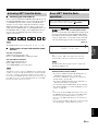
XM™ Satellite Radio tuning ............................... 58
Connecting XM™ Mini-Tuner Home Dock ........... 58
Activating XM™ Satellite Radio ............................ 59
Basic XM™ Satellite Radio operations................... 59
Setting the XM™ Satellite Radio
preset channels .................................................... 62
Displaying the XM™ Satellite Radio
information .......................................................... 63
Using iPod™.......................................................... 64
Controlling iPod™................................................... 64
Recording .............................................................. 66
Advanced sound configurations...........................67
Changing sound field parameter settings................. 67
Selecting decoders ................................................... 72
Customizing this unit (MANUAL SETUP).........75
Using SET MENU ................................................... 79
1 BASIC MENU...................................................... 80
2 VOLUME MENU ................................................ 84
3 SOUND MENU.................................................... 85
4 INPUT MENU...................................................... 88
5 OPTION MENU................................................... 91
Saving and recalling the system settings
(SYSTEM MEMORY)......................................96
Saving the current system settings........................... 96
Loading the stored system settings .......................... 97
Using examples........................................................ 98
Remote control features......................................100
Controlling this unit, a TV,
or other components .......................................... 100
Setting remote control codes ................................. 102
Programming codes
from other remote controls ................................ 104
Changing source names in the display window..... 105
Macro programming features ................................ 106
Clearing configurations ......................................... 109
Using multi-zone configuration..........................111
Connecting the Zone 2 and Zone 3
components........................................................ 111
Controlling Zone 2 or Zone 3 ................................ 112
Advanced setup....................................................117
Using the advanced setup menu ............................ 117
Troubleshooting...................................................121
Resetting the system............................................129
Glossary................................................................130
Sound field program information......................134
Parametric equalizer information .....................135
Specifications .......................................................136
Index .....................................................................138
(at the end of this manual)
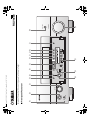
Front Panel ...............................................................i
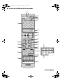
Remote Control ...................................................... ii
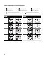
Sound output in each sound field program......... iii
List of remote control codes ...................................v
Contents
INTRODUCTION
PREPARATION
BASIC OPERATION
ADVANCED OPERATION
ADDITIONAL INFORMATION
APPENDIX
“
A
MASTER ON/OFF” or “
1
DVD” (example) indicates
the name of the parts on the front panel or the remote control.
Refer to the attached sheet or the pages at the end of this
manual for the information about each position of the parts.

NOTICE
2 En
We Want You Listening For A Lifetime
Yamaha and the Electronic Industries Association’s
Consumer Electronics Group want you to get the
most out of your equipment by playing it at a safe
level. One that lets the sound come through loud and
clear without annoying blaring or distortion – and,
most importantly, without affecting your sensitive
hearing. Since hearing damage from loud sounds is often
undetectable until it is too late, Yamaha and the Electronic
Industries Association’s Consumer Electronics Group
recommend you to avoid prolonged exposure from excessive
volume levels.
Manufactured under license from Dolby Laboratories.
“Dolby”, “Pro Logic”, and the double-D symbol are trademarks
of Dolby Laboratories.
Manufactured under license under U.S. Patent No’s:
5,451,942;5,956,674;5,974,380;5,978,762;6,226,616;6,487,535
& other U.S. and worldwide patents issued & pending. DTS is a
registered trademark and the DTS logos, Symbol, DTS-HD and
DTS-HD Master Audio are trademark of DTS, Inc. © 1996-2007
DTS, Inc. All Rights Reserved.
“iPod” is a trademark of Apple Inc., registered in the U.S. and
other countries.
“HDMI”, the “HDMI” logo and “High-Definition Multimedia
Interface” are trademarks, or registered trademarks of HDMI
Licensing LLC.
“SILENT CINEMA” is a trademark of YAMAHA
CORPORATION.
The XM name and related logos are registered trademarks of XM
Satellite Radio Inc.
This product is manufactured under license from Neural Audio
Corporation and THX Ltd. YAMAHA CORPORATION hereby
grants the user a non-exclusive, non-transferable, limited right of
use to this product under U.S.A. and foreign patent, patent
pending and other technology or trademarks owned by Neural
Audio Corporation and THX Ltd. “Neural Surround”, “Neural
Audio”, “Neural” and “NRL” are trademarks and logos owned by
Neural Audio Corporation. THX is a trademark of THX Ltd.,
which may be registered in some jurisdictions. All rights
reserved.
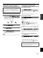
Notice
About this manual
• y indicates a tip for your operation.
• Some operations can be performed by using either the
buttons on the front panel or the ones on the remote
control. In case the button names differ between the front
panel and the remote control, the button name on the
remote control is given in parentheses.
• This manual is printed prior to production. Design and
specifications are subject to change in part as a result of
improvements, etc. In case of differences between the
manual and product, the product has priority.
•“
A
MASTER ON/OFF” or “
1
DVD” (example)
indicates the name of the parts on the front panel or the
remote control. Refer to the attached sheet or the pages at
the end of this manual for the information about each
position of the parts.
•
The symbol “☞ ” with page number(s) indicates the
corresponding reference page(s).
iPod
TM

FEATURES
3 En
INTRODUCTION
English
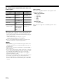
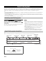
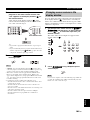
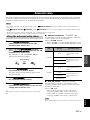
Built-in 7-channel power amplifier
◆ Minimum RMS output power
(20 Hz to 20 kHz, 0.04% THD, 8 Ω)
Front: 130 W + 130 W
Center: 130 W
Surround: 130 W + 130 W
Surround back: 130 W + 130 W
Sound field programs
◆ Proprietary Yamaha technology for the creation of sound
fields
◆ Compressed Music Enhancer mode to improve the sound
quality of compression artifacts (such as the MP3 format) to
that of a high-quality multi-channel source playback
◆ Virtual CINEMA DSP
◆ SILENT CINEMA
Digital audio decoders
◆ Dolby TrueHD, Dolby Digital Plus decoder
◆ DTS-HD Master Audio, DTS-HD High Resolution Audio
decoder
◆ Dolby Digital/Dolby Digital EX decoder
◆ DTS/DTS-ES Matrix 6.1, Discrete 6.1, DTS 96/24 decoder
◆ Dolby Pro Logic/Dolby Pro Logic II/Dolby Pro Logic IIx
decoder
◆ DTS NEO:6 decoder
◆ Neural-THX Surround decoder
(U.S.A. and Canada models only)
Sophisticated FM/AM tuner
◆ 40-station random and direct preset tuning
◆ Automatic preset tuning
◆ Preset station shifting capability (preset editing)
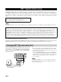
XM™ Satellite Radio
◆ XM Satellite Radio tuning capability (using XM Mini-Tuner
and Home Dock, sold separately)
◆ Neural-THX Surround decoder to play back the XM HD
content of XM Satellite Radio broadcasts in multi-channels,
resulting in a full surround sound experience
◆ XM Satellite Radio information displaying capability
HDMI™ (High-Definition Multimedia Interface)
◆ HDMI interface for standard, enhanced or
high-definition video as well as multi-channel digital audio
based on HDMI version 1.3a
◆ Automatic audio and video synchronization (lip sync)
information capability
◆ Deep Color video signal (30/36 bit) transmission capability
◆ High refresh rate and high resolution video signals capability
◆ High definition digital audio format signals capability
◆ Analog video to HDMI digital video up-conversion
(composite video ↔ S-video ↔ component video → HDMI
digital video) capability for monitor out
◆ Analog video up-scaling from 480i (NTSC)/576i (PAL) or
480p/576p to 720p, 1080i or 1080p
iPod™ controlling capability
◆ DOCK terminal to connect a Yamaha iPod universal dock
(such as the YDS-10, sold separately), which supports iPod
(Click and Wheel), iPod nano, and iPod mini
Other features
◆ YPAO (Yamaha Parametric Room Acoustic Optimizer) for
automatic speaker setup
◆ 192-kHz/24-bit D/A converter
◆ OSD (on-screen display) menus that allow you to optimize
this unit to suit your individual audiovisual system
◆ 6 or 8-channel additional input jacks for discrete multi-
channel input
◆ Analog video interlace/progressive conversion from
480i (NTSC)/576i (PAL) to 480p/576p
◆ S-video signal input/output capability
◆ Component video input/output capability includes
(3 COMPONENT VIDEO INs and 1 MONITOR OUT)
◆ Optical and coaxial digital audio signal jacks
◆ Pure Direct mode for pure hi-fi sound for all sources
◆ Adaptive dynamic range controlling capability
◆ Adaptive DSP effect level controlling capability
◆ Remote control with preset remote control codes, learning and
macro capability
◆ ZONE 2/ZONE 3 custom installation facility
◆ Zone switching capability between the main zone and
ZONE 2/ZONE 3 using ZONE CONTROLS
◆ SYSTEM MEMORY capability for saving and recalling
multiple system parameter settings
◆ Sleep timer
Features

Features
4 En
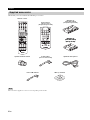
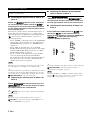
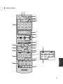
Check that you received all of the following accessories.
The form of the supplied accessories varies depending on the models.
Supplied accessories
Note
Remote control
Batteries (6)
(AAA, R03, UM-4)
(except Europe model)
AM loop antenna
Optimizer microphoneSpeaker terminal wrench Power cables
(Two for Asia model)
Indoor FM antenna
TUNER
CD
CD-R
MD/TAPE DVD BD/HD DVD
PHONO
DTV/CBL
VCR
V-AUX/DOCK
DVR
POWER
XM
STANDBY
A-E/CAT.
PRESET/CH
A/B/C/D/E
PRESET
VOLUME
ZONE 3
ZONE 2
ID2
ID1
NUMBER
CAT.
ALL
PRESET
DISPLAY
MUTE
1
2
3
4
5
ENT
6
7
8
9
0
Zone 2/Zone 3
remote control
(except Europe model)
Batteries (4)
(AAA, R03, UM-4)
(Europe model)
Batteries (4)
(AAA, R03, UM-4)
(Europe model)
–
+
+
––
+
ENTER
DISPLAY
AUDI O
MENU
TITLE
TV MUTE
TV INPUT
MUTE
4
3
2
ENT
+
10
0
9
5
1
AV
TV
7
6
8
RETURN
ON
OFF
CLEAR
LEARN
RENAME
MACRO
REC
DISC SKIP
VOLUME
CH
TV VOL
EFFECT
PARAMETER
STRAIGHT
XM MEMORY
A-E/CAT.
SRCH MODE
PURE DIRECT
PRESET/CH
SET MENU
BAN
D
LEVEL
CLASSICAL LIVE/CLUB
ENTERTAIN
MOVIE
SYSTEM MEMORY
SUR. DECODE
ENHANCERSTEREO
TV
SOURCE
AMP
SELECT
DTV/CBL VCRDVR
V-AUX/DOCK
TUNER CD CD-R
MULTI CH IN
POWER
POWER
POWER
STANDBY
SLEEPAUDIO SELXM
DVD BD/HD DVD PHONOMD/TAPE

GETTING STARTED
5 En
INTRODUCTION
English
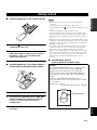
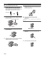
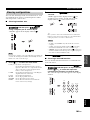
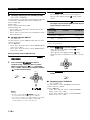
■ Installing batteries in the remote control
1 Press the part and slide the battery
compartment cover off.
2 Insert the four supplied batteries
(AAA, R03, UM-4) according to the polarity
markings (+ and –) on the inside of the
battery compartment.
3 Slide the cover back until it snaps into place.
■ Installing batteries in the Zone 2/Zone 3
remote control (Except Europe model)
1 Take off the battery compartment cover.
2 Insert the two supplied batteries (AAA, R03,
UM-4) according to the polarity markings
(+ and –) on the inside of the battery
compartment.
3 Snap the battery compartment cover back
into place.
• Change all of the batteries if you notice the following
conditions:
– the operation range of the remote control decreases.
– the transmit indicator (
O
) does not flash or its light becomes
dim.
• Do not use old batteries together with new ones.
• Do not use different types of batteries (such as alkaline and
manganese batteries) together. Read the packaging carefully as
these different types of batteries may have the same shape and
color.
• If the batteries have leaked, dispose of them immediately. Avoid
touching the leaked material or letting it come into contact with
clothing, etc. Clean the battery compartment thoroughly before
installing new batteries.
• Do not throw away batteries with general house waste; dispose
of them correctly in accordance with your local regulations.
• If the remote control is without batteries for more than 2
minutes, or if exhausted batteries remain in the remote control,
the contents of the memory may be cleared. When the memory
is cleared, insert new batteries, set up the remote control code
and program any acquired functions that may have been
cleared.
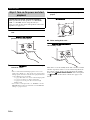
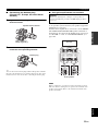
■ VOLTAGE SELECTOR
(Asia and General models only)
Getting started
1
3
2
1
3
2
Notes
Caution
The VOLTAGE SELECTOR on the rear panel of this
unit must be set for your local voltage BEFORE
plugging the power cable into the AC wall outlet.
Improper setting of the VOLTAGE SELECTOR may
cause damage to this unit and create a potential fire
hazard.
Rotate the VOLTAGE SELECTOR clockwise or
counterclockwise to the correct position using a straight
slot screwdriver.
Voltages are as follows:
........................AC 110/120/220/230–240 V, 50/60 Hz
230-
240V
VOLTAGE
SELECTOR
Voltage indication

QUICK START GUIDE
6 En
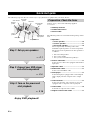
The following steps describe the easiest way to enjoy DVD movie playback in your home theater.
In these steps, you need the following supplied
accessories.
❏ AM loop antenna
❏ Indoor FM antenna
❏ Power cable
The following items are not included in the package of this
unit.
❏ Speakers
❏ Front speaker ..................................... x 2
❏ Center speaker ................................... x 1
❏ Surround speaker .............................. x 4
Select magnetically shielded speakers. The
minimum required speakers are two front speakers.
The priority of the requirement of other speakers is
as follows:
1. Two surround speakers
2. One center speaker
3. One (or two) surround back speaker(s)
❏ Active subwoofer ................................... x 1
Select an active subwoofer equipped with an RCA
input jack.
❏ Speaker cable ......................................... x 7
❏ Subwoofer cable ..................................... x 1
Select a monaural RCA cable.
❏ DVD player .............................................. x 1
Select DVD player equipped with coaxial digital
audio output jack and composite video output
jack.
❏ Video monitor .......................................... x 1
Select a TV monitor, video monitor or projector
equipped with a composite video input jack.
❏ Video cable ............................................. x 2
Select RCA composite video cables.
❏ Digital coaxial audio cable .................... x 1
Quick start guide
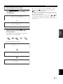
Front right
speaker
Subwoofer
Surround back
right speaker
Surround left
speaker
Front left
speaker
Surround back left
speaker
Surround right
speaker
Center
speaker
Video monitor
DVD player
Enjoy DVD playback!
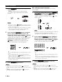
Step 1: Set up your speakers
☞ P. 7
Step 2: Connect your DVD player
and other components
Step 3: Turn on the power and
start playback
☞ P. 8
☞ P. 10
Preparation: Check the items

Quick start guide
7 En
INTRODUCTION
English
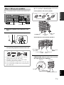
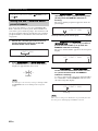
Place your speakers in the room and connect them to this
unit.
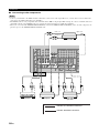
1 Place your speakers and subwoofer in the
room.
2 Connect speaker cables to each speaker.
3 Connect each speaker cable to the
corresponding speaker terminal of this unit.
1 Make sure that this unit and the subwoofer are
unplugged from the AC wall outlets.
2 Twist the exposed wires of the speaker cables
together to prevent short circuits.
3 Do not let the bare speaker wires touch each other.
4 Do not let the bare speaker wires touch any metal
part of this unit.
Be sure to connect the left channel (L), right channel
(R), “+” (red) and “–” (black) properly.
Front speakers and center speaker
Surround and surround back speakers
4 Connect the subwoofer cable to the
SUBWOOFER PRE OUT jack of this unit and
the input jack of the subwoofer.
Step 1: Set up your speakers
AC IN
AC OUTLETS
SWITCHED
HOLDER
WRENCH
SPEAKERS
CENTER
BI-AMP
SURROUND BACK/
PRESENCE/ZONE 2/ZONE 3
SP1
FRONT
SURROUND
ZONE 2/ZONE 3
SINGLE
SP2
ANTENNA
FM
GND
AM
75Ω UNBAL.
VIDEO
S VIDEO
MONITOR OUT
VIDEO
REMOTE
PHONO
GND
CD
IN(PLAY)
OUT(REC)
CD-R
HDMI
COMPONENT VIDEO
AUDIO
DOCK
XM
DIGITAL INPUT
MULTI CH INPUT
PRE OUT
TRIGGER OUT
RS-232C
DIGITAL OUTPUT
ZONE OUT
SUB
WOOFER
SUB
WOOFER
CENTER
CENTER
FRONT(6CH)
FRONT
SURROUND
SURROUND
PRESENCE
SUR.BACK/
SINGLE(SB)
ZONE 2
ZONE 3
CD
DVD
DVR
COAXIAL
1
2
CD
BD/
HD DVD
DTV/
CBL
MD/
TAPE
DVD CD-R
OPTICAL
987
65
4
321
SB(8CH)
DVD
TAPE
MD/
(REC)
(PLAY)
IN
OUT
BD/HD DVD
VCR
DVR
DTV/CBL
OUT OUT
ININ
BD/HD DVD
DVD
DTV/CBL
MONITOR OUT
Y
P
R
Y
P
R
P
B
P
B
IN
OUT
DVR
DTV/
CBL
DVD
BD/
HD DVD
OUT
+
+
+
A B C
R
L
R
R
L
R
L
+ + +
R
L
+ +
R
L
+ +
R
L
L
IN2
IN3
IN4
IN1
SUBWOOFER PRE OUT Speaker terminals
12 3 4
12 3 4
To the front left
speaker
To the front right
speaker
Loosen Insert
Speaker terminal wrench
To the center
speaker
Tighten
To the surround
back
right speaker
To the surround
back left
speaker
To the surround right
speaker
To the surround left
speaker
SUBWOOFER PRE OUT jack
Input jack
AV receiverSubwoofer
Subwoofer cable

Quick start guide
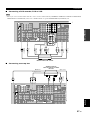
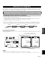
8 En
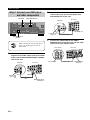
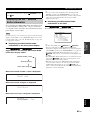
1 Connect the digital coaxial audio cable to the
digital coaxial audio output jack of your DVD
player and the DVD DIGITAL INPUT COAXIAL
jack of this unit.
2 Connect the video cable to the composite
video output jack of your DVD player and
DVD VIDEO jack of this unit.
3 Connect the video cable to the VIDEO
MONITOR OUT jack of this unit and the video
input jack of your video monitor.
Step 2: Connect your DVD player
and other components
AC IN
AC OUTLETS
SWITCHED
HOLDER
WRENCH
SPEAKERS
CENTER
BI-AMP
SURROUND BACK/
PRESENCE/ZONE 2/ZONE 3
SP1
FRONT
SURROUND
ZONE 2/ZONE 3
SINGLE
SP2
ANTENNA
FM
GND
AM
75Ω UNBAL.
VIDEO
S VIDEO
MONITOR OUT
VIDEO
REMOTE
PHONO
GND
CD
IN(PLAY)
OUT(REC)
CD-R
HDMI
COMPONENT VIDEO
AUDIO
DOCK
XM
DIGITAL INPUT
MULTI CH INPUT
PRE OUT
TRIGGER OUT
RS-232C
DIGITAL OUTPUT
ZONE OUT
SUB
WOOFER
SUB
WOOFER
CENTER
CENTER
FRONT(6CH)
FRONT
SURROUND
SURROUND
PRESENCE
SUR.BACK/
SINGLE(SB)
ZONE 2
ZONE 3
CD
DVD
DVR
COAXIAL
1
2
CD
BD/
HD DVD
DTV/
CBL
MD/
TAPE
DVD CD-R
OPTICAL
987
65
4
321
SB(8CH)
DVD
TAPE
MD/
(REC)
(PLAY)
IN
OUT
BD/HD DVD
VCR
DVR
DTV/CBL
OUT OUT
ININ
BD/HD DVD
DVD
DTV/CBL
MONITOR OUT
Y
P
R
Y
P
R
P
B
P
B
IN
OUT
DVR
DTV/
CBL
DVD
BD/
HD DVD
OUT
+
+
+
A B C
R
L
R
R
L
R
L
+ + +
R
L
+ +
R
L
+ +
R
L
L
IN2
IN3
IN4
IN1
Make sure that this unit and the DVD
player are unplugged from the AC
wall outlets.
VIDEO MONITOR OUTDVD VIDEO
DVD DIGITAL INPUT
COAXIAL
Digital coaxial
audio output
jack
Digital coaxial audio
cable
DVD DIGITAL INPUT
COAXIAL jack
DVD player
AV receiver
Composite video
output jack
Video cable
DVD VIDEO jack
DVD player
AV receiver
Video monitor
AV receiver
Video cable
VIDEO MONITOR
OUT jack
Video input jack

Quick start guide
9 En
INTRODUCTION
English
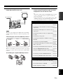
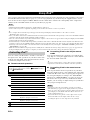
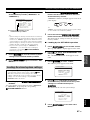
4 Connect the supplied AM loop antenna and
indoor FM antenna to this unit.
The types of the supplied indoor FM antenna and the FM
antenna terminal of this unit are different depending on the
models.
Connecting the wire of the AM loop antenna
y
The wire of the AM loop antenna does not have any polarity
and you can connect either end of the wire to AM or GND
terminal.
Assembling the supplied AM loop antenna
5 Connect the supplied power cable to this unit
and then plug of the power cable and other
components into the AC wall outlet.
y
• This unit is equipped with AC OUTLET(S) that provide(s)
power to other components (except Korea model). See
page 32 for details.
• (Asia model only) Select one of the supplied power cables
suitable for the type of AC wall outlet in your location
before plugging this unit into the AC wall outlet.
Note
Indoor FM antenna
AM loop antenna
Press and hold
the tab
Insert Release the tab
For further connections
• Using other kinds of speaker combinations
☞ P. 14
• Connecting a video monitor via various ways of
connection ☞ P. 24
• Connecting a DVD player via various ways of
connection ☞ P. 25
• Connecting a DVD recorder or a digital video
recorder ☞ P. 27
• Connecting a set-top box ☞ P. 27
• Connecting a CD player, an MD recorder, or a
turntable ☞ P. 28
• Connecting an external amplifier ☞ P. 29
• Connecting a DVD player via multi-channel analog
audio connection ☞ P. 30
• Connecting a Yamaha iPod universal dock ☞ P. 31
• Using the REMOTE IN/OUT jacks ☞ P. 31
• Using the VIDEO AUX jacks on the front panel
☞ P. 31
• Connecting an outdoor FM/AM antenna ☞ P. 32
• Connecting XM Mini-Tuner Home Dock ☞ P. 58
General connection information
• General information on jacks and cable plugs
☞ P. 20
• General information on HDMI ☞ P. 21–22
• Speaker impedance settings ☞ P. 33

Quick start guide
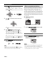
10 En
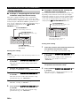
1 Turn on the video monitor connected to this
unit.
2 Press
A
MASTER ON/OFF inward to the ON
position on the front panel.
3 Rotate the
C
INPUT selector to set the input
source to “DVD”.
y
• The recommended sound field program is set for each
input source (DVD, etc.). You can also use various sound
field programs and other sound modes for playback. Refer
to the following pages for details:
– see pages 46 to 50 to use various sound field programs
– see page 51 to turn on or off the sound effect
– see page 52 to use the pure direct mode for high
fidelity sound
• You can also set the input source to “TUNER” to use the
FM/AM tuning feature. For information on the FM/AM
tuning, see pages 54 to 57.
4 Start playback of the desired DVD on your
player.
5 Rotate
Q
VOLUME to adjust the volume.
■ After using this unit...
Press
B
MAIN ZONE ON/OFF to set this unit to
the standby mode.
This unit is set to the standby mode and consumes a small
amount of power in order to receive infrared signals from
the remote control. To turn on this unit from the standby
mode, press
B
MAIN ZONE ON/OFF on the front panel
(or
8
POWER on the remote control). See page 33 for
details.
Step 3: Turn on the power and start
playback
Check the type of the connected speakers.
If the speakers are 6-ohm speakers, set “SPEAKER
IMP.” to “6Ω MIN” before using this unit (see
page 33). You can also use 4-ohm speakers as the front
speakers (see page 117).

Quick start guide
11 En
INTRODUCTION
English
What do you want to do with this unit?
Using various input sources
• Basic operations of this unit ☞ P. 42
• Enjoying FM/AM radio programs ☞ P. 54
• Enjoying XM Satellite Radio programs ☞ P. 58
• Using your iPod with this unit ☞ P. 64
Using various sound features
• Using various sound field programs ☞ P. 46
• Using the Pure Direct mode for high fidelity sound
☞ P. 52
• Adjusting the tonal quality of the speakers ☞ P. 52
• Customizing the sound field programs ☞ P. 67
Adjusting the parameters of this unit
• Automatically optimizing the speaker parameters for
your listening room (AUTO SETUP) ☞ P. 37
• Setting the remote control ☞ P. 100
Additional features
• Displaying the current input source signal
information in the OSD ☞ P. 44
• Saving and recalling the system settings of this unit
(SYSTEM MEMORY) ☞ P. 96
• Using headphones ☞ P. 43
• Using this unit in multiple rooms simultaneously
(multi-zone configuration) ☞ P. 111
• Automatically turning off this unit ☞ P. 45
Manually adjusting various parameters
of this unit
• Setting the basic speaker configuration ☞ P. 80
• Adjusting the balance of the speaker levels ☞ P. 82
• Setting the distance of each speaker ☞ P. 83
• Setting the parameters related to the volume level
☞ P. 84
• Adjusting the tonal quality by using the graphic
equalizer ☞ P. 85
• Adjusting the lip sync function for the HDMI
connection ☞ P. 87
• Assigning the input/output jacks of this unit
☞ P. 89
• Setting the parameters of the front panel display or
OSD ☞ P. 91
• Setting the parameters related to the video signals
☞ P. 92
• Protecting the various settings ☞ P. 93
• Setting the parameters of the multi-zone feature
☞ P. 94
Adjusting the advanced parameters
• Setting the speaker impedance of the connected
speakers ☞ P. 117
• Setting the parameters of this unit to default values
☞ P. 120

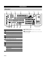
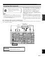
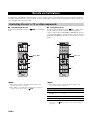
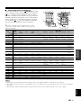
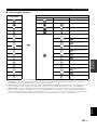
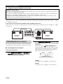
12 En
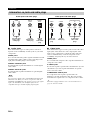
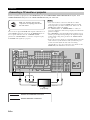
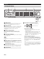
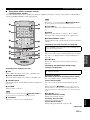
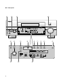
A TRIGGER OUT jacks
These are control expansion terminals for custom installation.
B RS-232C terminal
This is a control expansion terminal for factory use only. Consult
your dealer for details.
Connections
Rear panel
AC IN
AC OUTLETS
SWITCHED
HOLDER
WRENCH
SPEAKERS
CENTER
BI-AMP
SURROUND BACK/
PRESENCE/ZONE 2/ZONE 3
SP1
FRONT
SURROUND
ZONE 2/ZONE 3
SINGLE
SP2
ANTENNA
FM
GND
AM
75Ω UNBAL.
VIDEO
S VIDEO
MONITOR OUT
VIDEO
REMOTE
PHONO
GND
CD
IN(PLAY)
OUT(REC)
CD-R
HDMI
COMPONENT VIDEO
AUDIO
DOCK
XM
DIGITAL INPUT
MULTI CH INPUT
PRE OUT
TRIGGER OUT
RS-232C
DIGITAL OUTPUT
ZONE OUT
SUB
WOOFER
SUB
WOOFER
CENTER
CENTER
FRONT(6CH)
FRONT
SURROUND
SURROUND
PRESENCE
SUR.BACK/
SINGLE(SB)
ZONE 2
ZONE 3
CD
D
VD
D
VR
COAXIAL
1
2
CD
BD/
HD DVD
DTV/
CBL
MD/
TAP E
DVD CD-R
OPTICAL
987
65
4
321
SB(8CH)
DVD
TAP E
MD/
(REC)
(PLAY)
IN
OUT
BD/HD DVD
VCR
DVR
DTV/CBL
OUT OUT
ININ
BD/HD DVD
DVD
DTV/CBL
MONITOR OUT
Y
P
R
Y
P
R
P
B
P
B
IN
OUT
DVR
DTV/
CBL
DVD
BD/
HD DVD
OUT
+
+
+
A B C
R
L
R
R
L
R
L
+ + +
R
L
+ +
R
L
+ +
R
L
L
IN2
IN3
IN4
IN1
2 314567
A
B098C
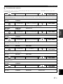
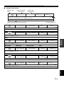
Name Page
1 HDMI jacks 21
2 COMPONENT VIDEO jacks 24 – 27
3 Audio component jacks 28
REMOTE IN/OUT jacks 31, 111
4 Video component jacks 24 – 27
5 ANTENNA terminals 32
6 VOLTAGE SELECTOR
(Asia and General models only)
32
7 AC IN 32
AC OUTLET(S) 32
8 DOCK terminal 31
9 XM jack (U.S.A. and Canada models only) 58
0 DIGITAL INPUT/OUTPUT jacks 25
C MULTI CH INPUT jacks 30
PRE OUT jacks 29
ZONE OUT jacks 111
Speaker terminals 16
WRENCH HOLDER 18

13 En
Connections
PREPARATION
English
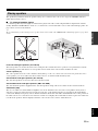
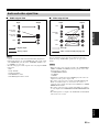
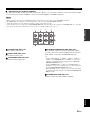
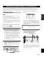
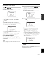
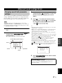
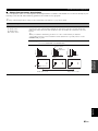
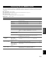
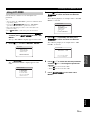
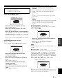
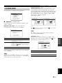
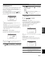
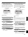
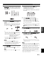
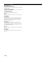
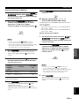
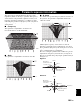
The speaker layout below shows the speaker setting we recommend. You can use it to enjoy the CINEMA DSP and
multi-channel audio sources.
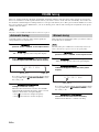
■ 7.1-channel speaker layout
7.1-channel speaker layout is highly recommended to play back of the sound of high definition digital audio formats
(Dolby TrueHD, DTS-HD Master Audio, etc.) as well as the conventional audio sources with sound field programs. See
page 16 for connection information.
y
We recommend that you also add the presence speakers for the effect sounds of the CINEMA DSP sound field program. See page 46 for
details.
Front left and right speakers (FL and FR)
The front speakers are used for the main source sound plus effect sounds. Place these speakers at an equal distance from the
ideal listening position. The distance of each speaker from each side of the video monitor should be the same.
Center speaker (C)
The center speaker is for the center channel sounds (dialog, vocals, etc.). If for some reason it is not practical to use a
center speaker, you can do without it. Best results, however, are obtained with the full system.
Surround left and right speakers (SL and SR)
The surround speakers are used for effect and surround sounds.
Surround back left and right speakers (SBL and SBR)
The surround back speakers supplement the surround speakers and provide more realistic front-to-back transitions.
Subwoofer (SW)
The use of a subwoofer with a built-in amplifier, such as the Yamaha Active Servo Processing Subwoofer System, is
effective not only for reinforcing bass frequencies from any or all channels, but also for reproducing the high fidelity
sound of the LFE (low-frequency effect) channel included in bitstreams and multi-channel PCM sources. The position of
the subwoofer is not so critical, because low bass sounds are not highly directional. But it is better to place the subwoofer
near the front speakers. Turn it slightly toward the center of the room to reduce wall reflections.
Placing speakers
SW
FR
FL
SBR
SBL
SL
SR
C
60˚
30˚
SBR
SBL
FL
FR
C
SL
SR
SR
80˚
SL
1.8 m (6 ft)
30 cm (12 in) or more

14 En
Connections
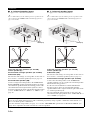
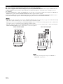
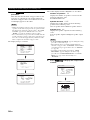
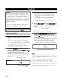
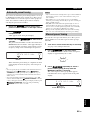
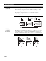
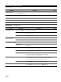
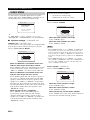
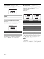
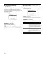
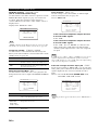
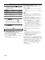
■ 6.1-channel speaker layout
See page 17 for connection information.
y
We recommend that you also add the presence speakers for the
effect sounds of the CINEMA DSP sound field program. See
page 15 for details.
Front left and right speakers (FL and FR)
Center speaker (C)
Surround left and right speakers (SL and SR)
Subwoofer (SW)
The function and settings of each speaker are the same as
those for the 7.1-channel speaker layout (see page 13).
Surround back speaker (SB)
Connect a single surround speaker to the SURROUND
BACK (SINGLE) speaker terminals and place the single
surround back speaker behind the listening position. The
surround back left and right channel signals are mixed
down and output at the single surround back speaker when
you set “SUR.B L/R SP” to “SMLx1” or “LRGx1” (see
page 81).
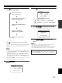
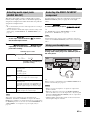
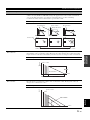
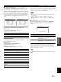
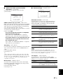
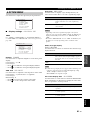
■ 5.1-channel speaker layout
See page 17 for connection information.
y
We recommend that you also add the presence speakers for the
effect sounds of the CINEMA DSP sound field program. See
page 15 for details.
Front left and right speakers (FL and FR)
Center speaker (C)
Subwoofer (SW)
The function and settings of each speaker are the same as
those for the 7.1-channel speaker layout (see page 13).
Surround left and right speakers (SL and SR)
Connect the surround speakers to the SURROUND
speaker terminals even if you place the surround speakers
behind the listening position.
For the smooth and unbroken sound field behind the
listening position, place the surround left and right
speakers farther back compared with the placement in the
7.1-channel speaker layout.
The surround back channel signals are directed to the
surround left and right speakers when “SUR.B L/R SP” is
set to “NONE” (see page 81).
SW
FR
FL
SB
SL
SR
C
60˚
30˚
SB
FL
FR
C
SL
SR
SR
80˚
SL
1.8 m (6 ft)
SW
FR
FL
SL
SR
C
60˚
30˚
FL
FR
C
SL
SR
SR
80˚
SL
1.8 m (6 ft)
For other speaker combinations
You can enjoy multi-channel sources with sound field programs by using a speaker combination other than the 7.1/
6.1/5.1-channel speaker combinations.
Use the automatic setup feature (see page 37) or set the “SPEAKER SET” parameters in “MANUAL SETUP” (see
page 80) to output the surround sounds at the connected speakers.

15 En
Connections
PREPARATION
English
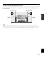
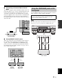
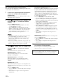
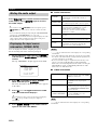
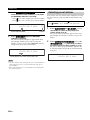
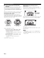
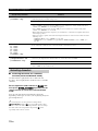
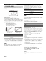
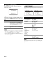
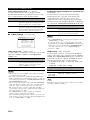
■ Presence left and right speakers (PL and PR)
The presence speakers supplement the sound from the front speakers with extra ambient effects produced by the sound field
programs (see page 46). We recommend that you use the presence speakers especially for the CINEMA DSP sound field
programs. To use the presence speakers, connect the speakers to SP1 speaker terminals and then set “PRESENCE SP” to
“YES” (see page 81).
You can connect both surround back and presence speakers to this unit, but they do not output sound simultaneously. This unit
automatically switches the presence speakers and surround back speakers depending on the input sources and the selected sound field
programs. You can set to prioritize either set of speakers using the “PRIORITY” parameter in “MANUAL SETUP” (see page 82).
Note
FR
PRPL
C
FL
1.8 m (6 ft)
0.5 to 1 m (1 to 3 ft) 0.5 to 1 m (1 to 3 ft)
1.8 m (6 ft)

16 En
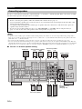
Connections
Be sure to connect the left channel (L), right channel (R), “+” (red) and “–” (black) properly. If the connections are faulty,
this unit cannot reproduce the input sources accurately.
• A speaker cord is actually a pair of insulated cables running side by side. Cables are colored or shaped differently, perhaps with a
stripe, groove or ridge. Connect the striped (grooved, etc.) cable to the “+” (red) terminals of this unit and your speaker. Connect the
plain cable to the “–” (black) terminals.
• You can use the SP1 terminals to connect the Zone 2 or Zone 3 speakers as well as the presence speakers (see page 111).
• You can connect both surround back and presence speakers to this unit, however they do not output sound simultaneously. This unit
automatically switches the presence speakers and surround back speakers depending on the input sources and the selected sound field
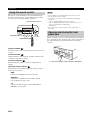
programs. You can set to prioritize either set of speakers using the “PRIORITY” parameter in “MANUAL SETUP” (see page 82).
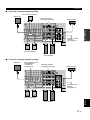
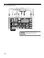
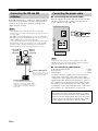
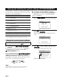
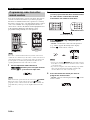
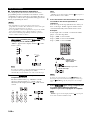
■ For the 7.1-channel speaker setting
Connecting speakers
Caution
• Before connecting the speakers, make sure that this unit is turned off (see page 33).
• Do not let the bare speaker wires touch each other or do not let them touch any metal part of this unit. This could
damage this unit and/or speakers.
• Use magnetically shielded speakers. If this type of speaker still creates interference with the monitor, place the
speakers away from the monitor.
• If you are to use 6-ohm speakers, be sure to set “SPEAKER IMP.” to “6Ω MIN” before using this unit (see
page 33). You can also use 4-ohm speakers as the front speakers (see page 117).
Notes
SPEAKERS
CENTER
BI-AMP
SURROUND BACK/
PRESENCE/ZONE 2/ZONE 3
SP1
FRONT
SURROUND
ZONE 2/ZONE 3
SINGLE
SP2
PRE OUT
SUB
WOOFER
+
+
+
R
L
R
L
+ + +
R
L
+ +
R
L
+ +
R
L
Front speakers
Surround speakers
Presence speakers
Subwoofer
Right
Left
Left
Center speaker
Surround back speakers
Right
Left
Left
Right
Right
Zone 2 or Zone 3
speakers
(see page 111)
Sayfa yükleniyor...
Sayfa yükleniyor...
Sayfa yükleniyor...
Sayfa yükleniyor...
Sayfa yükleniyor...
Sayfa yükleniyor...
Sayfa yükleniyor...
Sayfa yükleniyor...
Sayfa yükleniyor...
Sayfa yükleniyor...
Sayfa yükleniyor...
Sayfa yükleniyor...
Sayfa yükleniyor...
Sayfa yükleniyor...
Sayfa yükleniyor...
Sayfa yükleniyor...
Sayfa yükleniyor...
Sayfa yükleniyor...
Sayfa yükleniyor...
Sayfa yükleniyor...
Sayfa yükleniyor...
Sayfa yükleniyor...
Sayfa yükleniyor...
Sayfa yükleniyor...
Sayfa yükleniyor...
Sayfa yükleniyor...
Sayfa yükleniyor...
Sayfa yükleniyor...
Sayfa yükleniyor...
Sayfa yükleniyor...
Sayfa yükleniyor...
Sayfa yükleniyor...
Sayfa yükleniyor...
Sayfa yükleniyor...
Sayfa yükleniyor...
Sayfa yükleniyor...
Sayfa yükleniyor...
Sayfa yükleniyor...
Sayfa yükleniyor...
Sayfa yükleniyor...
Sayfa yükleniyor...
Sayfa yükleniyor...
Sayfa yükleniyor...
Sayfa yükleniyor...
Sayfa yükleniyor...
Sayfa yükleniyor...
Sayfa yükleniyor...
Sayfa yükleniyor...
Sayfa yükleniyor...
Sayfa yükleniyor...
Sayfa yükleniyor...
Sayfa yükleniyor...
Sayfa yükleniyor...
Sayfa yükleniyor...
Sayfa yükleniyor...
Sayfa yükleniyor...
Sayfa yükleniyor...
Sayfa yükleniyor...
Sayfa yükleniyor...
Sayfa yükleniyor...
Sayfa yükleniyor...
Sayfa yükleniyor...
Sayfa yükleniyor...
Sayfa yükleniyor...
Sayfa yükleniyor...
Sayfa yükleniyor...
Sayfa yükleniyor...
Sayfa yükleniyor...
Sayfa yükleniyor...
Sayfa yükleniyor...
Sayfa yükleniyor...
Sayfa yükleniyor...
Sayfa yükleniyor...
Sayfa yükleniyor...
Sayfa yükleniyor...
Sayfa yükleniyor...
Sayfa yükleniyor...
Sayfa yükleniyor...
Sayfa yükleniyor...
Sayfa yükleniyor...
Sayfa yükleniyor...
Sayfa yükleniyor...
Sayfa yükleniyor...
Sayfa yükleniyor...
Sayfa yükleniyor...
Sayfa yükleniyor...
Sayfa yükleniyor...
Sayfa yükleniyor...
Sayfa yükleniyor...
Sayfa yükleniyor...
Sayfa yükleniyor...
Sayfa yükleniyor...
Sayfa yükleniyor...
Sayfa yükleniyor...
Sayfa yükleniyor...
Sayfa yükleniyor...
Sayfa yükleniyor...
Sayfa yükleniyor...
Sayfa yükleniyor...
Sayfa yükleniyor...
Sayfa yükleniyor...
Sayfa yükleniyor...
Sayfa yükleniyor...
Sayfa yükleniyor...
Sayfa yükleniyor...
Sayfa yükleniyor...
Sayfa yükleniyor...
Sayfa yükleniyor...
Sayfa yükleniyor...
Sayfa yükleniyor...
Sayfa yükleniyor...
Sayfa yükleniyor...
Sayfa yükleniyor...
Sayfa yükleniyor...
Sayfa yükleniyor...
Sayfa yükleniyor...
Sayfa yükleniyor...
Sayfa yükleniyor...
Sayfa yükleniyor...
Sayfa yükleniyor...
Sayfa yükleniyor...
Sayfa yükleniyor...
Sayfa yükleniyor...
Sayfa yükleniyor...
Sayfa yükleniyor...
Sayfa yükleniyor...
Sayfa yükleniyor...
Sayfa yükleniyor...
Sayfa yükleniyor...
Sayfa yükleniyor...
Sayfa yükleniyor...
Sayfa yükleniyor...
Sayfa yükleniyor...
Sayfa yükleniyor...
Sayfa yükleniyor...
Sayfa yükleniyor...
Sayfa yükleniyor...
-
 1
1
-
 2
2
-
 3
3
-
 4
4
-
 5
5
-
 6
6
-
 7
7
-
 8
8
-
 9
9
-
 10
10
-
 11
11
-
 12
12
-
 13
13
-
 14
14
-
 15
15
-
 16
16
-
 17
17
-
 18
18
-
 19
19
-
 20
20
-
 21
21
-
 22
22
-
 23
23
-
 24
24
-
 25
25
-
 26
26
-
 27
27
-
 28
28
-
 29
29
-
 30
30
-
 31
31
-
 32
32
-
 33
33
-
 34
34
-
 35
35
-
 36
36
-
 37
37
-
 38
38
-
 39
39
-
 40
40
-
 41
41
-
 42
42
-
 43
43
-
 44
44
-
 45
45
-
 46
46
-
 47
47
-
 48
48
-
 49
49
-
 50
50
-
 51
51
-
 52
52
-
 53
53
-
 54
54
-
 55
55
-
 56
56
-
 57
57
-
 58
58
-
 59
59
-
 60
60
-
 61
61
-
 62
62
-
 63
63
-
 64
64
-
 65
65
-
 66
66
-
 67
67
-
 68
68
-
 69
69
-
 70
70
-
 71
71
-
 72
72
-
 73
73
-
 74
74
-
 75
75
-
 76
76
-
 77
77
-
 78
78
-
 79
79
-
 80
80
-
 81
81
-
 82
82
-
 83
83
-
 84
84
-
 85
85
-
 86
86
-
 87
87
-
 88
88
-
 89
89
-
 90
90
-
 91
91
-
 92
92
-
 93
93
-
 94
94
-
 95
95
-
 96
96
-
 97
97
-
 98
98
-
 99
99
-
 100
100
-
 101
101
-
 102
102
-
 103
103
-
 104
104
-
 105
105
-
 106
106
-
 107
107
-
 108
108
-
 109
109
-
 110
110
-
 111
111
-
 112
112
-
 113
113
-
 114
114
-
 115
115
-
 116
116
-
 117
117
-
 118
118
-
 119
119
-
 120
120
-
 121
121
-
 122
122
-
 123
123
-
 124
124
-
 125
125
-
 126
126
-
 127
127
-
 128
128
-
 129
129
-
 130
130
-
 131
131
-
 132
132
-
 133
133
-
 134
134
-
 135
135
-
 136
136
-
 137
137
-
 138
138
-
 139
139
-
 140
140
-
 141
141
-
 142
142
-
 143
143
-
 144
144
-
 145
145
-
 146
146
-
 147
147
-
 148
148
-
 149
149
-
 150
150
-
 151
151
-
 152
152
-
 153
153
-
 154
154
-
 155
155
-
 156
156
-
 157
157


Yamaha RX-V1800 El kitabı
- Kategori
- AV alıcıları
- Tip
- El kitabı
- Bu kılavuz aynı zamanda aşağıdakiler için de uygundur:
diğer dillerde
- español: Yamaha RX-V1800 El manual del propietario
- français: Yamaha RX-V1800 Le manuel du propriétaire
- italiano: Yamaha RX-V1800 Manuale del proprietario
- svenska: Yamaha RX-V1800 Bruksanvisning
- čeština: Yamaha RX-V1800 Návod k obsluze
- polski: Yamaha RX-V1800 Instrukcja obsługi
- Deutsch: Yamaha RX-V1800 Bedienungsanleitung
- português: Yamaha RX-V1800 Manual do proprietário
- English: Yamaha RX-V1800 Owner's manual
- dansk: Yamaha RX-V1800 Brugervejledning
- русский: Yamaha RX-V1800 Инструкция по применению
- suomi: Yamaha RX-V1800 Omistajan opas
- Nederlands: Yamaha RX-V1800 de handleiding
- română: Yamaha RX-V1800 Manualul proprietarului
İlgili makaleler
-
Yamaha RX-V3800 El kitabı
-
Yamaha RX-V2500 El kitabı
-
-
-
Yamaha RX-V459 - AV Receiver - 6.1 Channel Kullanım kılavuzu
-
-
-
-
-
Yamaha RX-V3900 Kullanım kılavuzu