
Owner’s Manual
AV Receiver English

En 2
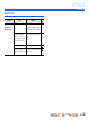
CONTENTS
INTRODUCTION
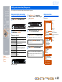
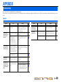
Features and capabilities................................................... 3
About this manual............................................................. 4
Supplied accessories.........................................................4
Part names and functions.................................................. 5
Front panel........................................................................5
Rear panel.........................................................................6
Front panel display ...........................................................7
Remote control ................................................................. 8
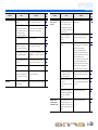
CONNECTIONS
Connecting speakers .......................................................... 9
Speaker channels and functions........................................ 9
Speaker layout ................................................................10
Connecting speakers.......................................................10
Connecting external devices............................................12
Cable plugs and jacks .....................................................12
Connecting a TV monitor...............................................13
Connecting BD/DVD players and other devices ............15
Connecting the FM antenna............................................17
Setting up speaker parameters .......................................18
STEP 1: Display the setting menu..................................18
STEP 2: Set the speaker status and size .........................18
STEP 3: Set the distance from the listening point..........19
STEP 4: Playback a test tone.......................................... 20
STEP 5: Adjust the volume ............................................20
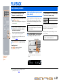
PLAYBACK
Basic playback procedure ............................................... 21
Adjusting high/low-frequency sound (Tone control) .....21
Changing input settings with a single key
(SCENE function) ............................................................22
Registering input sources/sound field program .............. 22
Enjoying sound field programs.......................................22
Selecting sound field programs and sound decoders......22
Sound field programs ..................................................... 24
FM tuning......................................................................... 26
Selecting a frequency for reception (Normal tuning)..... 26
Registering and recalling a frequency (Preset tuning) ... 27
Clearing preset stations .................................................. 29
SETUP
Configuring the settings specific for each input source
(Option menu) .................................................................. 30
Option menu display and setup ...................................... 30
Option menu items ......................................................... 30
Setting various functions (Setup menu)......................... 33
Setup menu display and settings .................................... 33
Setup menu items ........................................................... 33
Manages settings for speakers........................................ 34
Setting the audio output function of this unit................. 37
Setting HDMI functions ................................................. 38
Making the receiver easier to use ................................... 40
Setting sound field program parameters......................... 41
Prohibiting setting changes ............................................ 41
Setting sound field program parameters ....................... 42
Setting sound field parameters ....................................... 42
Extended functionality that can be configured
as needed (Advanced Setup menu)................................. 44
Displaying/Setting the Advanced Setup menu............... 44
Avoiding crossing remote control signals when using
multiple Yamaha receivers ............................................. 44
Changing FM frequency steps
(Asia and General models only)..................................... 45
Initializing various settings for this unit......................... 45
Using the HDMI Control function ................................. 46
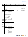
APPENDIX
Troubleshooting ............................................................... 49
General ........................................................................... 49
HDMI™ ......................................................................... 52
Tuner (FM) ..................................................................... 52
Remote control............................................................... 53
Glossary............................................................................ 54
Audio information.......................................................... 54
Sound field program information................................... 55
Video information .......................................................... 55
Information on HDMI™................................................. 56
About trademarks ........................................................... 56
Specifications.................................................................... 57
Index ................................................................................. 58

En 3
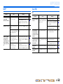
INTRODUCTION
■ Built-in high-quality, high-power 5-channel amplifier
■ 1-button input/sound field program switching (SCENE function) .......................22
■ Speaker connections for 2- to 5.1-channel configurations
– Speaker channels and functions .................................................................................................................9
– Speaker layout..........................................................................................................................................10
– Speaker/subwoofer cable connection.......................................................................................................10
■ Acoustic parameter adjustment to match your speakers and listening
environment
– Setting for speaker acoustic parameters...................................................................................................18
– Specifying the settings for each speaker..................................................................................................34
– Volume control for each speaker..............................................................................................................35
– Speaker distance settings .........................................................................................................................35
– Sound quality control with the equalizer <Graphic Equalizer> ..............................................................36
– Test tone speaker adjustment ...................................................................................................................36
– Bass and treble level adjustment <Tone Control> ...................................................................................21
■ External device connection and playback
– Cables and input/output jacks for this unit ..............................................................................................12
– TV connection..........................................................................................................................................13
– TV audio playback through this receiver.................................................................................................13
– Connections for BD/DVD players (recorders) and other devices............................................................15
– Audio signal output to the TV connected via the HDMI jack .................................................................39
– Correction of lag between audio and video signals <Lipsync>...............................................................37
– HDMI video input combining other audio input .....................................................................................31
– Changing the input source names <Input Rename> ................................................................................40
– Configuring the settings specific for each input source <Option menu> ................................................30
– Playback from external devices ...............................................................................................................21
■ FM Tuner
– FM broadcast listening.............................................................................................................................26
– Simple preset tuning ................................................................................................................................27
– Changing FM frequency steps initializing various settings for this unit .................................................26
■ Multi-channel, multi-format playback
– Sound field effect selection......................................................................................................................22
– Playback without sound field effects .......................................................................................................23
– Stereo playback........................................................................................................................................23
– Sound field effect configuration...............................................................................................................42
– Compressed-music playback ...................................................................................................................22
■ Front panel information display
– Front panel display information switching ................................................................................................7
– Front panel display brightness adjustment <Dimmer>............................................................................41
– Digital video/audio signal information display <Signal Info> ................................................................31
■ Volume/sound quality adjustment functions
– Easy listening at low volumes <Adaptive DRC> ....................................................................................37
– Maximum volume settings.......................................................................................................................38
– Startup volume settings............................................................................................................................38
– Adjusting volume between input sources <Volume Trim> .....................................................................31
■ Remote control operation
– Remote control names and functions.........................................................................................................8
– Insert batteries into the remote control ......................................................................................................4
– Multiple Yamaha receiver operation without signal interference <Remote ID Switching>....................44
■ Other features
– Standby mode after prolonged non-operation <Auto Power Down function>........................................41
– Standby mode after a specific amount of time <Sleep timer>...................................................................8
– Initializing various settings for this unit ..................................................................................................45
– Prohibiting setting changes <Memory Guard>........................................................................................41
Features and capabilities

En 4
INTRODUCTION
Features and capabilities
About this manual Supplied accessories
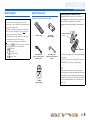
Check that you received all of the following parts.
• This manual is printed prior to production. Design and
specifications are subject to change in part as a result of
improvements, etc. In case of differences between the manual and
product, the product has priority.
• “
dHDMI1” (example) indicates the name of the parts on the
remote control. Refer to the “Remote control” (☞
p. 8) for the
information about each position of the parts.
• J
1 indicates that the reference is in the footnote. Refer to the
corresponding numbers on the bottom of the page.
• ☞
indicates the page describing the related information.
• Click on the “ ” at the bottom of the page to display the
corresponding page in “Part names and functions.”
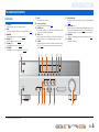
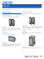
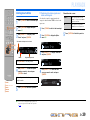
Front panel
Rear panel
Front panel display
Remote control
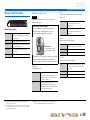
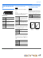
Remote control Batteries (2)
(AAA, R03, UM-4)
Indoor FM antenna
(for U.S.A., Canada, General,
and Asia models)
Indoor FM antenna
(for U.K., Europe and Australia
models)
CD-ROM
(Owner’s Manual)
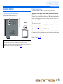
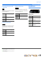
■ Installing batteries in the remote control
When inserting batteries in the remote control, remove the
battery compartment cover from the reverse side of the remote
control, and insert two AAA batteries into the battery
compartment so that they match with the polarity markings (+
and -).
Replace the batteries with new ones if the following symptoms
become evident:
• The remote control can only be operated within a narrow range.
•
bTRANSMIT does not light up, or only lights dimly.
NOTE
If there are remote control codes for external components
registered to the remote control, removing the batteries for more
than two minutes, or leaving exhausted batteries in the remote
control, the remote control codes may be cleared. If this should
occur, replace the batteries with new ones, and set the remote
control codes.
a
c
b
Battery compartment
cover
Battery compartment

En 5
INTRODUCTION
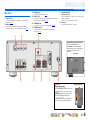
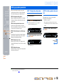
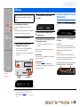
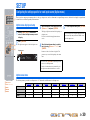
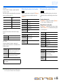
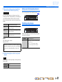
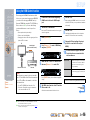
Front panel
a A (Power)
Switches this unit between on and standby modes.
b INFO
Changes the information shown on the front panel display (☞
p. 7).
c MEMORY
Registers FM stations as preset stations (☞
p. 28). J1
d PRESET j / i
Selects an FM preset station (☞
p. 28). J1
e TUNING jj / ii
Changes FM tuner frequencies (☞
p. 26). J1
f FM MODE
Switch FM reception stereo and monaural (☞
p. 27). J1
g MUTE
Switch muted and non-muted.
h Front panel display
Displays information on this unit (☞
p. 7).
i PHONES jack
For plugging headphones in. Sound effects applied during playback
can also be heard through the headphones.
j INPUT l / h
Selects an input source from which to playback. Press either the left or
right key repeatedly to cycle through the input sources in order.
k SCENE
Switches the input source and the sound field program with a single
button (☞
p. 22). Press this key when this unit is in standby mode to
switch on the unit.
l TONE CONTROL
Adjusts high-frequency/low-frequency output of speakers/headphones
(☞
p. 21).
m PROGRAM l / h
Switches between the sound field effect (sound field program) you are
using and the surround sound decoder (☞
p. 22). Press either the left
or right key repeatedly to cycle through the input sources in order.
n STRAIGHT
Changes a sound field program to straight decoding mode (☞
p. 23).
o VOLUME
Adjusts the volume level.
Part names and functions
PHONES
SILENT
CINEMA
TONE
CONTROL
STRAIGHT
VOLUME
TV
BD
DVD
CD
RADIO
INPUT
PROGRAM
SCENE
INFO
MEMORY
PRESET
FM MODE MUTETUNING
hb
l n oj m
a d e
ki
c fg
J
1 : Usable when you have selected tuner input.

En 6
INTRODUCTION
Part names and functions
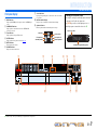
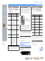
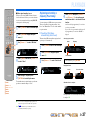
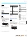
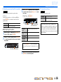
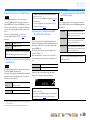
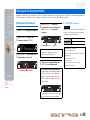
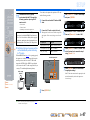
Rear panel
a HDMI OUT jack
For connecting an HDMI - compatible TV to output audio/video
signals to (☞
p. 13).
b HDMI1-3 jacks
For connecting external components equipped with HDMI-
compatible outputs to receive audio/video signals from (☞
p. 15).
c ANTENNA jacks
For connecting an FM antenna (☞
p. 17).
d AUDIO1-6 jacks
For connecting to external components equipped with audio outputs to
input audio signals into this unit (☞
p. 16).
e SUBWOOFER jack
For connecting a subwoofer with a built-in amplifier (☞
p. 11).
f SPEAKER terminals
For connecting the front, center, and surround speakers, and a
subwoofer (☞
p. 11).
g VOLTAGE SELECTOR
(General model only)
Select the switch position according to your local voltage using a
straight slot screwdriver.
Voltages are AC 110-120/220-240 V, 50/60 Hz.
h Power cord
For connecting this unit to an AC wall outlet.
ANT
E
F
M
(
CD
)
(
TV
)
COAXIALCOAXIAL
OPTICAL
OPTICAL
AUDIO 6
HDMI 2 HDMI 3
HDMI
SUBWOOFER
AUDIO 5AUDIO 4AUDIO 3AUDI O 2AUDI O 1
ANTE
FM
(
C
D
)
(
TV
)
CO
AXIAL
CO
AXIA
L
O
PTI
C
AL
O
PTI
C
A
L
A
U
DI
O
6
HDMI 2
HDMI
3
A
U
DI
O
5
A
U
DI
O
4
AU
DI
O
3
AU
DI
O
2A
U
DI
O
1
ANTENNA
FM
75
(
CD
)
(
TV
)
COAXIALCOAXIAL
OPTICAL
OPTICAL
AUDIO 6
CENTER
FRONT
HDMI 1
(
BD/DVD
)
HDMI 2 HDMI 3
SUB
WOOFER
SURROUND
HDMI
OUT
SUBWOOFER
SPEAKERS
VOLTAGE
SELECTOR
110V-
120V
220V-
240V
AUDIO 5AUDIO 4AUDIO 3AUDIO 2AUDIO 1
b
d
ca
h
ARC
gef
Distinguishing the input and output jacks
The area around HDMI OUT and
SUBWOOFER jacks is marked in white to
prevent connection errors. Use these jacks to
output audio/video signals to a TV or a
subwoofer.
Output jacks
CAUTION
(General model only)
The VOLTAGE SELECTOR on the rear panel
of this unit must be set for your local voltage
BEFORE plugging the power cable into the
AC wall outlet. Improper setting of the
VOLTAGE SELECTOR may cause damage to
this unit and create a potential fire hazard.
SELECTOR
110V-
120V
220V-
240V
VOLTAGE SELECTOR

En 7
INTRODUCTION
Part names and functions
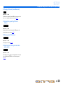
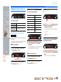
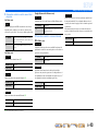
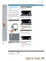
Front panel display
a HDMI indicator
Lights up when HDMI signals are input at the selected HDMI input
source.
b CINEMA DSP indicator
Lights up when a sound field effect that uses CINEMA DSP
technology is selected.
c Tuner indicator
Lights up when receiving an FM broadcast.
d SLEEP indicator
Lights up when the sleep timer is activated (☞
p. 8).
e MUTE indicator
Flashes when audio is muted.
f VOLUME indicator
Displays the current volume level.
g Cursor indicators
Light up if corresponding cursors on the remote control are available
for operations.
h Multi information display
Displays a range of information on menu items and settings.
i Speaker indicators
Indicate speaker terminals from which signals are output.
SW
C
LR
SL SR
Front speaker L
Surround speaker L
Subwoofer
Front speaker R
Surround speaker R
Center speaker
■ Changing the front panel display
The front panel can display sound field programs and surround
decoder names as well as the active input source.
Press fINFO repeatedly to cycle through input source →
sound field program → surround decoder in order. J1
SW
C
L
SL SR
R
STRAIGHT
HDMI1
VOL.
Input source name
Sound field program (DSP program)
STEREO
SLEEP
VOL.
TUNED
SW
C
LR
SL SR
MUTE
abcdfe
gh ig
J
1 : While selecting a tuner input, the FM frequency is displayed instead of the input source.

En 8
INTRODUCTION
Part names and functions
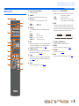
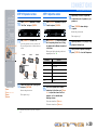
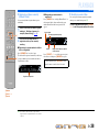
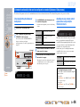
Remote control
a Remote control signal transmitter
Transmits infrared signals.
b TRANSMIT
Lights up when a signal is output from the remote control.
c Input selector
Select an input source on this unit from which to playback.
d TUNER keys
Operates the FM tuner. These keys are used when using the tuner
input.
e INFO
Cycles the information displayed on the front panel display (the name
of the currently selected input source, the sound field program, the
surround decoder, the FM tuner frequency, etc.)(☞
p. 7).
f SOUND selection keys
Switch between the sound field effect (sound field program) you are
using and the surround decoder (☞
p. 22).
g SCENE
Switches the input source and the sound field program with a single
button (☞
p. 22). Press this key when this unit is in standby mode to
switch on the unit.
h SETUP
Displays a detailed Setup menu for this unit (☞
p. 33).
i Cursor B / C / D / E, ENTER, RETURN
j SLEEP
Sets this unit to place itself in standby mode automatically after a
specified period of time has elapsed (sleep timer). Press this key
repeatedly to set the time for the sleep timer function. The front panel
display indicator lights up when the sleep timer is activated.
k RECEIVER A (RECEIVER Power)
Switches this unit between on and standby modes.
l OPTION
Displays the Option menu for each input source (☞
p. 30).
m VOLUME +/-
Adjusts the volume level (☞
p. 21).
n MUTE
Turns the mute function of the sound output on and off (☞
p. 21).
RECEIVER
SCENE
OPTION
SETUP
RETURN
VOLUME
TRANSMIT
SLEEP
BD
DVD
TV
CD
RADIO
MUTE
ENTER
123
123
456
HDMI
AUDIO
TUNER
SOUND
INFO
TUNER
MEMORY
PRESET
TUNING
SUR. DECODE
STRAIGHT
ENHANCER
STEREO
MUSICMOVIE
l
m
n
j
k
a
c
b
d
e
g
h
i
f
HDMI1-3 HDMI1-3 jacks
AUDIO1-6 AUDIO1-6 jacks
TUNER FM tuner
MEMORY Presets radio stations.
PRESET F / G Selects a preset station.
TUNING H / I Changes tuning frequencies.
Cursor B / C / D / E Select menu items and change settings when
settings menus, etc are displayed.
ENTER Confirms a selected item.
RETURN Returns to the previous screen when setting
menus are displayed, or ends the menu display.
Sleep 120min. Sleep 90min.
Sleep 60min.Sleep 30min.Sleep Off

En 9
CONNECTIONS
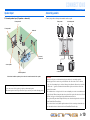
This unit uses acoustic field effects and sound decoders to bring you the impact of a real movie theater or concert hall. These effects will be brought to you with ideal speaker positioning and
connections in your listening environment.
Speaker channels and functions
■
Front left and right speakers
The front speakers are used for the front channel sounds (stereo sound) and effect sounds.
Front speaker layout:
Place these speakers at an equal distance from the ideal listening position in the front of the room.
When using a projector screen, the appropriate top positions of the speakers are about 1/4 of the screen
from the bottom.
■
Center speaker
The center speaker is for the center channel sounds (dialog, vocals, etc.).
Center speaker layout:
Place it halfway between the left and right speakers. When using a TV, place the speaker just above or
just under the center of the TV with the front surfaces of the TV and the speaker aligned.
When using a screen, place it just under the center of the screen.
■
Surround left and right speakers
The surround speakers are for effect and vocal sounds with the 5.1-channel speakers providing rear-
area sounds.
Surround speaker layout:
Place the speakers at the rear of the room on the left and right sides facing the listening position. They
should be placed between 60 degrees and 80 degrees from the listening position and with the speaker
tops at a height of 1.5 – 1.8 m from the floor.
■
Subwoofer
The subwoofer speaker is used for bass sounds and low-frequency effect (LFE) sounds included in
Dolby Digital and DTS.
Subwoofer speaker layout:
Place it exterior to the front left and right speakers facing slightly inward to reduce echoes from the
wall.
Connecting speakers
Ex.
Ex.
Ex.
Ex.

En 10
CONNECTIONS
Connecting speakers
Speaker layout
5.1-channel speaker layout (5 speakers + subwoofer)
Connecting speakers
Connect your speakers to their respective terminals on the rear panel.
• Connect at least two speakers (front left and right).
• If you cannot connect all five speakers, give priority to the surround speakers.
• The surround speakers should be placed between 60 degrees and 80 degrees from the listening position.
Front speaker R
Front speaker L
Center speaker
Surround speaker L
Surround
speaker R
Subwoofer
About how to install the speakers, please refer to the instruction manual of the speaker.
CAUTION
• Remove the AC power cord of this unit from the power outlet before connecting the speakers.
• Generally speaker cables consist of two parallel insulated cables. One of these cables is a different
color, or has a line running along it, to indicate different polarity. Insert the different colored (or lined)
cable into the “+” (positive, red) terminal on this unit and the speakers, and the other cable into the “-”
(minus, black) terminal.
• Be careful that the core of the speaker cable does not touch anything or come into contact with the metal
areas of this unit. This may damage this unit or the speakers. If the speaker cables short circuit, “Check
SP Wires” will appear on the front panel display when this unit is switched on.
• Use speakers having more than 6 Ω impedance when you use other than the speakers that are included
in the Yamaha Home Theatre Package.
• Use a subwoofer that is active (built-in amplier) and turn it off before connecting to the unit when you
use other than the subwoofer that is included in the Yamaha Home Theatre Package.
VOLTAGE
SELECTOR
110V-
120V
220V-
240V
ANTENNA
FM
75
CENTER
FRONT
SUB
WOOFER
SURROUND
SUBWOOFER
SPEAKERS
Front speaker Surround speaker
Center speaker Subwoofer
RL RL

En 11
CONNECTIONS
Connecting speakers
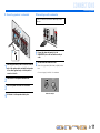
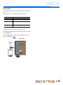
■
Connecting speakers / a subwoofer
1
Remove approximately 10mm of insulation from the
ends of the speaker cables, and twist the bare wires
of the cables together firmly so that they will not
cause short circuits.
2
Press the tab on the speaker terminal down.
3
Insert the speaker cable end into the terminal.
4
Lift the tab to fix the speaker cable in place.
■
Connecting an active subwoofer
1
Connect the subwoofer input jack to the
SUBWOOFER jack on this unit with an audio pin
cable.
2
Set the subwoofer volume as follows.
Volume: Set to approximately half volume (or slightly less than
half).
Crossover frequency (if available): Set to maximum.
CENTER
FRONT
SPEAKERS
SUB
WOOFER
SURROUND
4
1
2
2
4
3
3
Connect to a subwoofer jack as follows when using an active
subwoofer.
VOLUME
MIN MAX
CROSSOVER/
HIGH CUT
MIN MAX
Subwoofer examples

En 12
CONNECTIONS
Cable plugs and jacks
The main unit is equipped with the following input/output jacks. Use jacks and cables appropriate for
components that you are going to connect.
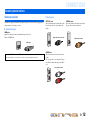
■
Audio/Video jacks
HDMI jacks
Digital video and digital sound are transmitted through a single jack.
Only use an HDMI cable.
■
Audio jacks
Connecting external devices
• Use a 19-pin HDMI cable with the HDMI logo.
• We recommend using a cable less than 5.0 m long to prevent signal quality degradation.
HDMI cable
OPTICAL jacks
These jacks transmit optical digital audio signals.
Use fiber-optic cables for optical digital audio
signals.
COAXIAL jacks
These jacks transmit coaxial digital audio signals.
Use pin cables for digital audio signals.
AUDIO jacks
These jacks transmit conventional analog audio
signals.
Use stereo pin cables, connecting the red plug to
the red R jack, and the white plug to the white L
jack.
AUDIO 4
OPTICAL
(TV)
Digital audio fiber-optic cable
AUDIO 2
COAXIAL
Digital audio pin cable
AUDIO 5
Stereo audio pin cable

En 13
CONNECTIONS
Connecting external devices
Connecting a TV monitor
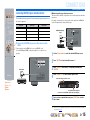
■
Connecting an HDMI video monitor
Connect the HDMI cable to the HDMI OUT jack.
■
Listening to TV audio
To transmit sound from the TV to this unit, connect as followings according to the TV:
When using a TV that supports the Audio Return Channel function and HDMI
Control function
When your TV supports both HDMI Control (Ex. Panasonic VIERA Link) and Audio Return Channel
functions, audio/video output from the unit to the TV and audio output from the TV to the unit are
possible using a single HDMI cable.
The input source is switched automatically to match operations carried out on the TV, and that makes
TV sound control easier to use.
For the connections and settings, refer to “Single HDMI cable input to TV audio with Audio Return
Channel function” (☞
p. 48).
When using a TV that supports the HDMI Control functions
When using a TV that supports HDMI Control functions (Ex. Panasonic VIERA Link), if HDMI
Control functions are enabled on the unit, then input source can be switched automatically to match
operations carried out on the TV.
For the connections and settings, refer to “Switching the input source on this unit automatically when
listening to TV audio” (☞
p. 47).
• Use a 19-pin HDMI cable with the HDMI logo.
• We recommend using a cable less than 5.0 m long to prevent signal quality degradation.
• When using a TV that supports Audio Return Channel function, audio/video signals can be transmitted
mutually between the unit and TV with a single HDMI cable (☞
p. 48).
HDMI
OUT
(
CD
)
(
TV
)
CO
AXIAL
CO
AXIAL
O
PTI
C
AL
O
PTI
C
AL
A
U
DI
O
6
HDMI 1
(
B
D
/
DV
D
)
HDMI 2
HDMI
3
AU
DI
O
5
A
U
DI
O
4
AU
DI
O
3
A
U
DI
O
2
AU
DI
O
1
HDMI
HDMI
HDMI
HDMI input
TV

En 14
CONNECTIONS
Connecting external devices
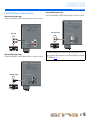
When using other TVs
To transmit sound from the TV to this unit, connect its AUDIO 1-6 jacks to the TV’s audio output
jacks.
Depending on the connection on TV, connect the TV’s audio output to the AUDIO 1-6.
Select the input source connected via TV’s audio output jack to enjoy the TV sound.
If the TV supports optical digital audio output, we recommend that you connect the TV audio output to
the receiver’s AUDIO 4 jack.
Connecting to AUDIO 4 allows you to switch the input source to AUDIO 4 with just a single key
operation using the SCENE function (☞
p. 22).
TV audio output Connection
Optical digital audio output Connect to AUDIO 1 or AUDIO 4 OPTICAL jack with a fiber-optic cable.
Coaxial digital audio output Connect to AUDIO 2 or AUDIO 3 COAXIAL jack with a digital audio pin
cable.
Analog stereo output Connect to AUDIO 5 or AUDIO 6 jack with a stereo pin cable.
(
CD
)
(
TV
)
COAXIALCOAXIAL
OPTICAL
OPTICAL
HDMI 1
(
BD/DV
D
)
HDMI
2
HDMI
3
HDMI
OU
T
OPTICAL
O
O
Audio output
(Optical)
TV
Available input jacks

En 15
CONNECTIONS
Connecting external devices
Connecting BD/DVD players and other devices
This unit has the following input jacks. Connect them to the appropriate output jacks on
the external components.
■
Connecting BD/DVD players and other devices with
HDMI
Connect the device with an HDMI cable to one of the HDMI1-3 jacks.
Select the HDMI input (HDMI1-3) that the external device is connected to for
playback.
■ Receiving audio from other input sources
This unit can use the AUDIO 1-6 input jacks to receive audio signals from other audio
input sources.
For example, if an external device cannot produce audio signals from an HDMI jack,
use the following method to change the audio input.
1
Use the cInput selector to select the desired HDMI input source.
2
Press lOPTION to display the Option menu. J1
3
Press iCursor C until “Audio In” is displayed, and then press
iENTER.
4
Press iCursor D / E to select the audio input source.
5
Once you have completed the setup, press lOPTION to close the
Option menu.
OPTION
ENTER
123
HDMI
RE
C
EIVE
R
SC
ENE
S
ET
U
P
RETURN
V
O
LUM
E
TRAN
S
MI
T
S
LEE
P
BD
DVD
T
V
CD
R
ADI
O
MUT
E
1
2
3
4
5
6
AUDI
O
TU
NE
R
SOU
ND
I
NF
O
TUNER
M
EM
O
RY
PRE
S
ET
TU
NIN
G
SU
R. DE
CO
DE
S
TRAI
G
HT
E
NHAN
C
ER
S
TERE
O
MU
S
I
C
MO
VIE
c
i
l
cInput selector
iCursor C / D / E
iENTER
lOPTION
Input jack Video input Audio input
HDMI1-3 HDMI HDMI
AUDIO 1, 4 — Optical digital
AUDIO 2, 3 — Coaxial digital
AUDIO 5, 6 — Analog (Stereo)
(
BD/DVD
)
(
C
D
)
(
TV
)
CO
AXIAL
CO
AXIAL
O
PTI
C
AL
O
PTI
C
A
L
AU
DI
O
6
HDMI
O
UT
AU
DI
O
5
A
U
DI
O
4
AU
DI
O
3
A
U
DI
O
2
AU
DI
O
1
HDMI
HDMI
HDMI
HDMI output
BD/DVD player
OPTICAL
(
BD/DVD
)
(
CD
)
(
TV
)
COAXIA
L
COAXIA
L
OPTICA
L
AUDI O
6
HDMI 2 HDMI
3
H
DMI
OU
T
AUDIO
5
A
UDIO
4
AUDIO
3
A
UDIO 2
HDMI
OPTICAL
HDMI
HDMI
O
O
HDMI/Audio (Optical)
output
BD/DVD player
SW
C
L
SL SR
R
Audio;;;AUDIO1
HDMI1
VOL.
If you have selected AUDIO 1 input audio (optical digital)
Inputs that change the audio source
Assignable audio input jacks
J
1 : See the section on “Configuring the settings specific for each input source (Option menu)” for details on
the Option menu (☞
p. 30).

En 16
CONNECTIONS
Connecting external devices
■
Connecting CD players and other audio devices
Using analog stereo output sources
Select the audio input (AUDIO 5 or AUDIO 6) that the external device is connected to for playback.
Using optical digital output sources
Select the audio input (AUDIO 1 or AUDIO 4) that the external device is connected to for playback.
Using coaxial digital output sources
Select the audio input (AUDIO 2 or AUDIO 3) that the external device is connected to for playback.
(
C
D
)
(
TV
)
CO
AXIAL
CO
AXIAL
O
PTI
C
AL
O
PTI
C
A
L
H
DMI 1
(
B
D
/
DV
D
)
HDMI 2
HDMI
3
HDMI
O
UT
A
U
DI
O
4
AU
DI
O
3
A
U
DI
O
2
AU
DI
O
1
AUDIO
R
L
R
L
Audio output
CD player
(
TV
)
OPTICAL
(
C
D
)
CO
AXIAL
CO
AXIAL
O
PTI
C
A
L
AU
DI
O
6
H
DMI
1
(
BD
/
DVD
)
HDMI 2
HDMI
3
HDMI
O
UT
AU
DI
O
5
AU
DI
O
3
AU
DI
O
2
A
U
DI
O
1
O
O
OPTICAL
CD player
Audio (Optical) output
We recommend connecting audio devices with an coaxial digital output to the AUDIO 3 coaxial
digital jack on this unit. This connection allows you to switch to the AUDIO 3 just by pressing the
“CD” SCENE key (☞
p. 22).
(
CD
)
COAXIALCOAXIAL
(
TV
)
O
PTI
C
A
L
O
PTI
C
AL
A
U
DI
O
6
HDMI
1
(
BD
/
DV
D
)
HDMI 2
HDMI
3
HDMI
O
U
T
A
U
DI
O
5
AU
DI
O
4
A
U
DI
O
1
C
C
COAXIAL
Audio (Coaxial) output
CD player

En 17
CONNECTIONS
An indoor FM antenna is included with this receiver. Connect these antenna properly to the ANTENNA
jack.
Connecting the FM antenna
■ Improving FM reception
We recommend using an outdoor antenna. For more information, consult the nearest authorized
dealer.
ANTENNA
FM
75
AU
DI
O
6
C
ENTER
F
R
O
N
T
H
DMI
3
S
UB
W
OO
FE
R
S
URR
O
UN
D
S
PEAKER
S
VOL
S
EL
E
1
1
0V
-
1
2
0
V
22
0
V-
240V
Indoor FM antenna

En 18
CONNECTIONS
When you have finished connecting your speakers,
configure this unit so that they output sound normally.
Carry out the following steps to configure this unit.
STEP 1: Display the setting menu
Display the Setup menu from which you can configure
all settings for this unit, and then display the menu for
speaker settings.
STEP 2: Set the speaker status and size
Set the size and connection status of speakers and
subwoofers, and whether to designate a specific speaker
(or subwoofer) for low-frequency sound.
STEP 3: Set the distance from the listening
point
Set the distance between the speakers and the listening
point so that the sound from each speaker reaches the
listening point at the appropriate timing.
STEP 4: Playback a test tone
Playback a test tone to allow you to configure sound
volumes while listening to the actual effect your settings
are having.
STEP 5: Adjust the volume
Adjust the volume for each speaker and configure them
so that the sound is balanced.
STEP 1: Display the setting menu
1
Switch this unit on.
2
Press hSETUP on the remote control.
The Setup menu that allows you to configure all
parameters on this unit appears. J1
3
Check that “Speaker Setup” appears and
press iENTER.
This completes step 1.
STEP 2: Set the speaker status and
size
The settings in step 2 are not necessary with the
following speaker configuration:
– Subwoofer: connected
– Front speaker: woofer diameter is 16 cm or larger
– Center/surround speakers: woofer diameter is 16 cm or
smaller
4
Check that “Config” appears and press
iENTER.
Setting up speaker parameters
SETUP
ENTER
RE
C
EIVE
R
SC
ENE
O
PTI
ON
RETURN
V
O
LUM
E
TRAN
S
MI
T
S
LEE
P
BD
DVD
T
V
CD
R
ADI
O
MUT
E
1
2
3
1
2
3
4
5
6
HDMI
AUDI
O
TU
NE
R
SOU
ND
I
NF
O
TUNER
M
EM
O
RY
PRE
S
ET
TU
NIN
G
SU
R. DE
CO
DE
S
TRAI
G
HT
E
NHAN
C
ER
S
TERE
O
MU
S
I
C
MO
VIE
i
h
hSETUP
iENTER
SW
C
L
SL SR
R
SpeakerSetup
SETUP
VO L.
SW
C
L
SL SR
R
Config
SP SET
VO L.
SW
C
L
SL SR
R
Subwoofer;;Yes
CONFIG
VOL.
Continues to the
next page
J
1 : See the section “Setting various functions (Setup menu)” for
details on the Setup menu (☞
p. 33).

En 19
CONNECTIONS
Setting up speaker parameters
5
Use iCursor B / C to select the speaker
(subwoofer) you want to configure, and
then use iCursor D / E to select speaker
status and size.
When you have completed the settings for one speaker,
repeat the same procedure for all speakers to complete
settings.
6
Press iRETURN when setting is complete.
Return to the previous menu.
This completes step 2.
STEP 3: Set the distance from the
listening point
7
Press iCursor C to display “Distance” and
press iENTER.
8
Press iCursor B / C to select the speaker
that you want to configure, and press
iCursor D / E to change the distance.
If necessary, you can change the setting units under
“Unit.”
When you have completed the settings for one speaker,
repeat the same procedure for all speakers to complete
settings.
9
Press iRETURN when setting is complete.
Return to the previous menu.
This completes step 3.
RETURN
ENTER
RE
C
EIVE
R
SC
ENE
O
PTI
ON
S
ET
U
P
V
O
LUM
E
TRAN
S
MI
T
S
LEE
P
BD
DVD
T
V
CD
R
ADI
O
MUT
E
1
2
3
1
2
3
4
5
6
HDMI
AUDI
O
TU
NE
R
SOU
ND
I
NF
O
TUNER
M
EM
O
RY
PRE
S
ET
TU
NIN
G
SU
R. DE
CO
DE
S
TRAI
G
HT
E
NHAN
C
ER
S
TERE
O
MU
S
I
C
MO
VIE
i
iCursor B / C / D / E
iENTER
iRETURN
Information Description Setting
Subwoofer Sets the subwoofer status. Yes / None
Front Selects the size (sound
reproduction capacity) of the
front speakers.
Small /
Large
Center Selects the size of the center
speakers. Choose “None” if
you do not have a center
speaker connected.
None /
Small /
Large
Sur. LR Selects the size of the surround
speakers. Choose “None” if
you do not have surround
speakers connected.
None /
Small /
Large
Crossover Audio with a frequency below
this limit will be output from
the subwoofer or the front
speakers.
40Hz to
200Hz
SWFR Phase Switches the phase of the
subwoofer.
NRM / REV
Extra Bass Selects whether to play front
channel low-frequency
components through either of
the front speakers or the
subwoofer (Off), or through
both the subwoofer and front
speakers (On).
On / Off
This setting is not needed when you use the speakers
that are included in the Yamaha Home Theatre
Package.
■ The case of general speakers
• Whether or not you set “Crossover,” “SWFR Phase,”
and “Extra Bass” is optional. Check how the effects
sound and then configure them to your liking.
• Use the following as a guide when setting speaker
sizes.
When speaker size is set to “Small,” low-frequency
components of the speakers you configured are
produced from the subwoofer (or from the front
speakers if there is no subwoofer).
Woofer diameter
• 16 cm or larger → Large
• 16 cm or smaller → Small
SW
C
L
SL SR
R
Unit;;;;meters
DIST
VOL.
Information Description Setting
Unit Switches between setting
units (feet / meters).
meters (m) /
feet (ft)
Front L Front speaker L 0.30 m to 24.00 m
(1.0 ft to 80.0 ft)
Front R Front speaker R 0.30 m to 24.00 m
(1.0 ft to 80.0 ft)
Center Center speaker 0.30 m to 24.00 m
(1.0 ft to 80.0 ft)
Sur. L Surround speaker L 0.30 m to 24.00 m
(1.0 ft to 80.0 ft)
Sur. R Surround speaker R 0.30 m to 24.00 m
(1.0 ft to 80.0 ft)
SWFR Subwoofer 0.30 m to 24.00 m
(1.0 ft to 80.0 ft)
Continues to the
next page

En 20
CONNECTIONS
Setting up speaker parameters
STEP 4: Playback a test tone
10
Press iCursor C repeatedly to display
“Test Tone” and press iENTER.
11
Use iCursor D / E to select “On.”
A test tone plays back as soon as you select “On.”
The test tone plays back in a clockwise fashion, as
follows.
12
Check that the test tone is playing back
and press iRETURN.
Return to the previous menu.
This completes step 4.
STEP 5: Adjust the volume
13
Press iCursor B repeatedly to display
“Level” and press iENTER.
14
Use iCursor B / C to switch the speaker
that is outputting the test tone, looking
for speakers with a different volume level
to the others.
The front panel display shows the speaker that is
outputting the test tone. J1
15
If you find a speaker with a different
volume level to the others, use iCursor
D / E to adjust the volume. Use Front
speaker L or R as a default when
adjusting volumes.
To raise the volume: Press iCursor E.
To lower the volume: Press
iCursor D.
16
Repeat steps 14 and 15 to adjust the
volume balance for all speakers to your
preference.
17
Press iRETURN when setting is
complete.
Return to the previous menu.
This completes step 5.
18
Repeat procedures 10-12 (step 4) to stop
playback of the test tone.
19
Once you have completed all settings,
press hSETUP to close the Setup menu.
SETUP
RETURN
ENTER
RE
C
EIVE
R
SC
ENE
O
PTI
ON
V
O
LUM
E
TRAN
S
MI
T
S
LEE
P
BD
DVD
T
V
CD
R
ADI
O
MUT
E
1
2
3
1
2
3
4
5
6
HDMI
AUDI
O
TU
NE
R
SOU
ND
I
NF
O
TUNER
M
EM
O
RY
PRE
S
ET
TU
NIN
G
SU
R. DE
CO
DE
S
TRAI
G
HT
E
NHAN
C
ER
S
TERE
O
MU
S
I
C
MO
VIE
i
h
hSETUP
iCursor B / C / D / E
iENTER
iRETURN
SW
C
L
SL SR
R
>OffOn
TEST
VOL.
Front L Front RCenter
Subwoofer
Surround L Surround R
Information Speakers
FL Front speaker L
FR Front speaker R
C Center speaker
SL Surround speaker L
SR Surround speaker R
SWFR Subwoofer
SW
C
L
SL SR
R
FL----d----
d
LEVEL
VOL.
J
1 : Only speakers configured for use in procedure 5 output the test
tone.
Sayfa yükleniyor...
Sayfa yükleniyor...
Sayfa yükleniyor...
Sayfa yükleniyor...
Sayfa yükleniyor...
Sayfa yükleniyor...
Sayfa yükleniyor...
Sayfa yükleniyor...
Sayfa yükleniyor...
Sayfa yükleniyor...
Sayfa yükleniyor...
Sayfa yükleniyor...
Sayfa yükleniyor...
Sayfa yükleniyor...
Sayfa yükleniyor...
Sayfa yükleniyor...
Sayfa yükleniyor...
Sayfa yükleniyor...
Sayfa yükleniyor...
Sayfa yükleniyor...
Sayfa yükleniyor...
Sayfa yükleniyor...
Sayfa yükleniyor...
Sayfa yükleniyor...
Sayfa yükleniyor...
Sayfa yükleniyor...
Sayfa yükleniyor...
Sayfa yükleniyor...
Sayfa yükleniyor...
Sayfa yükleniyor...
Sayfa yükleniyor...
Sayfa yükleniyor...
Sayfa yükleniyor...
Sayfa yükleniyor...
Sayfa yükleniyor...
Sayfa yükleniyor...
Sayfa yükleniyor...
Sayfa yükleniyor...
Sayfa yükleniyor...
-
 1
1
-
 2
2
-
 3
3
-
 4
4
-
 5
5
-
 6
6
-
 7
7
-
 8
8
-
 9
9
-
 10
10
-
 11
11
-
 12
12
-
 13
13
-
 14
14
-
 15
15
-
 16
16
-
 17
17
-
 18
18
-
 19
19
-
 20
20
-
 21
21
-
 22
22
-
 23
23
-
 24
24
-
 25
25
-
 26
26
-
 27
27
-
 28
28
-
 29
29
-
 30
30
-
 31
31
-
 32
32
-
 33
33
-
 34
34
-
 35
35
-
 36
36
-
 37
37
-
 38
38
-
 39
39
-
 40
40
-
 41
41
-
 42
42
-
 43
43
-
 44
44
-
 45
45
-
 46
46
-
 47
47
-
 48
48
-
 49
49
-
 50
50
-
 51
51
-
 52
52
-
 53
53
-
 54
54
-
 55
55
-
 56
56
-
 57
57
-
 58
58
-
 59
59


diğer dillerde
- español: Yamaha HTR-2064 El manual del propietario
- français: Yamaha HTR-2064 Le manuel du propriétaire
- italiano: Yamaha HTR-2064 Manuale del proprietario
- svenska: Yamaha HTR-2064 Bruksanvisning
- Deutsch: Yamaha HTR-2064 Bedienungsanleitung
- português: Yamaha HTR-2064 Manual do proprietário
- English: Yamaha HTR-2064 Owner's manual
- dansk: Yamaha HTR-2064 Brugervejledning
- русский: Yamaha HTR-2064 Инструкция по применению
- suomi: Yamaha HTR-2064 Omistajan opas
- Nederlands: Yamaha HTR-2064 de handleiding
- română: Yamaha HTR-2064 Manualul proprietarului