Yamaha DTX700 Kullanım kılavuzu
- Kategori
- Müzik davulları
- Tip
- Kullanım kılavuzu

DRUM TRIGGER MODULE
DTX700
Reference Manual
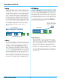
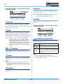
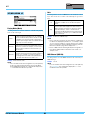
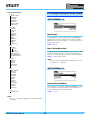
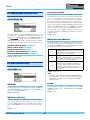
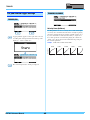
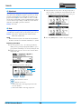
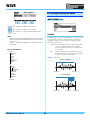
The DTX700 Reference Manual created via the PDF format is equipped with special features that are exclusive to electronic files, such as
the Link function and the Search function which let you jump to the desired page by clicking the specific term.
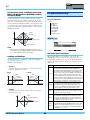
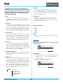
This illustration shows the page displayed on the DTX700 when the front panel’s [MENU] button is pressed. When you click on any of the
menu items, you will be taken to the start of the corresponding section.
This function built in the viewer software is very useful if you want to know the meaning of unfamiliar terms.
When using Adobe Reader to read this manual, enter a specific word in the search box, then press the <Enter> key of your computer key-
board to call up the relevant section in this manual.
NOTE
• Make sure to check and download the latest version of the Adobe Reader from the following site.
http://www.adobe.com/products/reader/
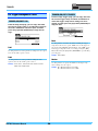
When using Adobe Reader, click to return to the previous page view/go to the next page view via the buttons in the toolbar.
This function is very useful if you want to return to the previous page view when jumping to a link page.
NOTE
• If the previous page view/next page view buttons are not shown in the toolbar, hold the <Alt> key and press < >/< > keys to move to
the previous/next page view.
• For more information on these and other functions in the software, refer to the owner’s manual of the software.
How to Use This Manual
Search Function
Previous Page View/Next Page View
EN

DTX700 Reference Manual 2
Internal Design of the DTX700
In this reference section, you will find a description of
what takes place within the DTX700 between striking
of a pad and the output of sound from speakers.
Understanding how signals flow and are processed
internally will allow you to utilize the powerful func-
tions of this versatile instrument to their maximum
potential.
Pads & Trigger Signals
Whenever you strike a pad, a trigger signal containing various
items of performance data will be produced. These signals typi-
cally reflect the strength with which the pad was struck, the actual
location of the strike, and the like; furthermore, they are delivered
via a cable and a trigger input jack to the DTX700’s internal tone
generator, which outputs the appropriate drum sounds in response.
If a pad is set up to generate just one sound, there will be a one-to-
one relationship between the trigger signal type and the drum voice
output. With certain types of pad, however, it is possible to produce
a range of different types of trigger signal that reflect the location
of the strike, the drumming technique being used, and other factors.
[Terminology]
Zone:
The term “zone” is used to refer to specific areas of the pad,
such as the rim, cup, and head. Pads with multiple zones (such
as two- and three-zone pads) can produce a different trigger sig-
nal for each. As their name suggests, one-zone pads produce
only one signal irrespective of where they are struck.
Trigger input source:
Trigger input sources are named in accordance with the way in
which the corresponding pad or pedal is struck or operated.
One-zone pads (producing a single trigger sig-
nal)
A mono pad such as the TP65 Single Zone Drum Pad or
PCY65 Single Zone Cymbal Pad transmits only one type of
trigger signal to the DTX700, irrespective of where it is struck.
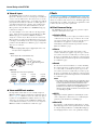
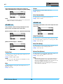
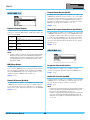
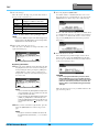
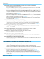
Two- and three-zone pads (producing multiple
trigger signals)
In contrast to the PCY65 Single Zone Cymbal Pad and other
mono pads, multi-zone pads such as the PCY65S Double Zone
Cymbal Pad can produce two different types of trigger signal
depending on the zone that is struck, while the PCY135 Triple
Zone Cymbal Pad can produce three. In specific terms, multi-
zone pads come in either the two-zone or three-zone variety.
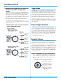
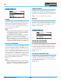
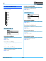
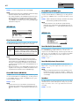
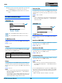
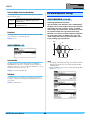
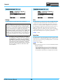
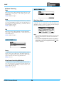
For instance, the PCY135 Triple Zone Cymbal Pad illustrated
below comprises three trigger input sources – the bow, the
edge, and the cup – each of which generates a trigger input sig-
nal when struck.
Example: PCY135 trigger input sources when connected
to the [yCRASH1] trigger input jack
Trigger input source:
“Crash1Bw”
The voice assigned
to the bow’s trigger
input source will be
played.
Trigger input source:
“Crash1Eg”
Trigger input source:
“Crash1Cp”
Bow
Edge
Cup
The voice assigned
to the edge’s trigger
input source will be
played.
The voice assigned
to the cup’s trigger
input source will be
played.

Internal Design of the DTX700
DTX700 Reference Manual
3
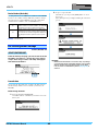
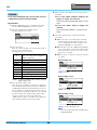
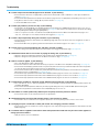
Example of how a pad controller can be used
to increase the number of trigger input
sources
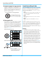
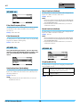
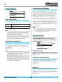
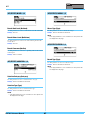
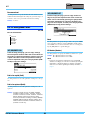
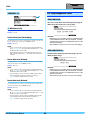
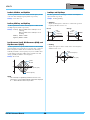
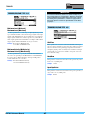
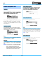
Consider, for example, a situation where an XP100SD Snare
Pad is connected to the [qSNARE] trigger input jack and the
PadCtrlType (Pad Control Type) parameter from the Menu
area’s Kit/Pad page is set to “snaresOn/Off”. As this pad com-
prises three zones – namely, the open rim (A), the closed rim
(B), and the head (C) – it will have three trigger input sources.
If the pad controller were then to be used to switch the
SnaresOn/Off (Snare Wire On/Off) parameter from “on” to
“off” or vice-versa, the pad could be made to have a total of six
trigger input sources.
Combining three zones and a pad controller to
give six trigger input sources
Trigger Setups
Your DTX700 uses a set of parameters called trigger setups to
ensure that trigger signals from pads and controllers are processed
in an ideal manner. In addition to the actual sensitivity of the pad
when it is struck, a trigger setup can include settings intended to
prevent a pair of trigger signals being produced in response to a
single strike (i.e., double triggering) and unwanted trigger signals
being produced by pads other than the one that was struck (i.e.,
crosstalk). The DTX700 comes pre-loaded with a total of 9 Preset
trigger setups suitable for many different needs, and you can also
create up to 20 unique User trigger setups to suit your own individ-
ual requirements.
Pads and trigger input jacks
As described above, some pads feature multiple trigger input
sources, each of which can generate its own trigger signals. It is the
role of the DTX700 to collect and process these signals, but the
types of trigger signal handled will depend on which of the trigger
input jacks is used for connection. For the most up-to-date infor-
mation on the correspondence between pad types and DTX700
trigger input jacks, please refer to the following web page.
http://dtxdrums.yamaha.com/
Drum Kits & Voices
Upon the receipt of a trigger signal, the DTX700’s internal tone
generator plays the voice assigned to the corresponding trigger
input source. The term “kit” is used to refer to a full set of voice
assignments for all trigger input sources, and the DTX700 comes
preloaded with 50 preset drum kits. You are, however, free to mod-
ify these drum kits in whatever way you see fit. In many cases, it is
sufficient to simply select one of the preset drum kits for your per-
formances, but if you wish to create original kits, it is important
that you understand the inner workings of the DTX700, including
the makeup of drum kits.
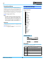
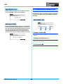
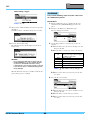
Voice assignments for trigger input sources
As voices may be freely assigned to each of the trigger input
sources sending trigger signals from the pads, original drum
kits may be easily configured. For details of the basic proce-
dure, see page16.
Example: XP100SD
When pad controller is
turned clockwise, setting
SnaresOn/Off to “on”:
Total of six
trigger input
sources
Trigger input
source:
“SnareOp”
Trigger input
source:
“SnareCl”
Trigger input
source:
“SnareHd”
When pad controller is turned
counter-clockwise, setting
SnaresOn/Off to “off”:
Trigger input
source:
“SnrOpOff”
Trigger input
source:
“SnrClOff”
Trigger input
source:
“SnrHdOff”
Individual voices for each trigger input source:
A: Drum voice assigned to
trigger input source A.
B: Drum voice assigned to
trigger input source B.
C: Drum voice assigned to
trigger input source C.

Internal Design of the DTX700
DTX700 Reference Manual
4
Instrument assignments for trigger input jacks
Assigning voices individually to each trigger input source can
be quite time consuming. In order to speed up this process, the
DTX700 features instrument parameters that group together the
drum voices assigned to the multiple trigger input sources cor-
responding to each trigger input jack – or in other words, the
drum voices assigned to each pad.
Voices grouped as kits
For most drummers, the preset drum kits built into the DTX700
are sufficient to provide a wide range of variation in perfor-
mances. If, however, you wish to customize these presets, you
can simply change the instrument set for each trigger input jack
to assign new voices to each of the corresponding pad’s trigger
input sources. If you wish to go even further, meanwhile, you
can also change voice assignments on an individual trigger
input source basis to create drum kits finely tuned to your indi-
vidual needs (see page16).
Sounds Produced Using the Pads
Whenever the DTX700’s internal tone generator receives a trigger
signal produced by striking a pad or by operating a controller, it will
play the voice or song assigned to that pad or controller. As
described below, three different types of assignment are supported –
namely, voices, songs, and waves.
• Voices
Drum sounds such as snares, bass drums, and cymbals; percus-
sion sounds; and pitched-instrument sounds such as piano,
xylophone, and guitar.
• Songs
Phrases containing performance data for a range of different
instruments.
•Waves
Audio files imported into the DTX700 from a variety of
sources.
The Menu area’s Kit/Voice page is used to assign voices, songs,
and waves to pads and controllers. On that page, available assign-
ments are categorized by musical instrument type (in the case of
voices), as songs, or as waves. While these three assignment types
can all be defined for pads in the same way, it is important to
remember that each type plays in a different way and is configured
using different parameters.
Voices
The DTX700 comes preloaded with a vast library of drum
sounds, such as snares, bass drums, and cymbals, together with
a broad spectrum of percussion-instrument sounds. Also
included are many pitched instruments, such as piano, xylo-
phone, and guitar. The term “voice” is used to refer to these
built-in instrument sounds. Drum and percussion voices from
this collection are not rooted at one specific pitch; instead, you
can intuitively adjust their tuning in order to match the sounds
of other instruments. Meanwhile, pitched-instrument voices
such as piano and guitar can be assigned to pads with a specific
pitch setting, thus allowing you to play several different notes
together to produce chords; in addition, you can also have pads
trigger successive notes from a phrase each time they are
struck, making it possible to play melodic parts (see page21).
With the timing and strength of your playing reflected in the
sound produced by preset voices, you can perform with practi-
cally the same level of expressiveness as afforded by acoustic
instruments.
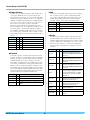
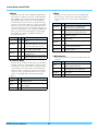
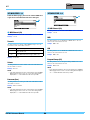
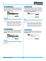
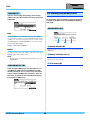
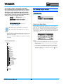
Choosing instruments for each trigger input jack
By selecting an instrument, all of the
voices assigned to a pad’s three trigger
input sources can be changed together.
Three-zone pads (like the PCY135):
Single-zone pads (like the KP65):
Trigger
input
source
Layer
*1
MIDI
note
number
Layer
*2
Instrument
Crash1Bw
Layer A Note No. Voice
Instrument
Layer B Note No. Voice
Layer C Note No. Voice
Layer D Note No. Voice
Crash1Eg
Layer A Note No. Voice
Layer B Note No. Voice
Layer C Note No. Voice
Layer D Note No. Voice
Crash1Cp
Layer A Note No. Voice
Layer B Note No. Voice
Layer C Note No. Voice
Layer D Note No. Voice
Trigger
input
source
Layer
*1
MIDI
note
number
Layer
*2
Instrument
Kick
Layer A Note No. Voice
Instrument
Layer B Note No. Voice
Layer C Note No. Voice
Layer D Note No. Voice
*1: See page 6 for details.
*2: Sounds set using the VoiceCategory
and VoiceNumber parameters from
the Menu area’s Kit/Voice page.

Internal Design of the DTX700
DTX700 Reference Manual
5
Songs
The DTX700 allows you to play complete songs simply by
striking one pad. In the same way as snare sounds are produced
by striking a pad to which a snare voice has been assigned, you
can start and stop the playback of songs by striking the pads to
which they are assigned. In effect, pads with song assignments
operate as start/stop switches whenever struck (regardless of
how hard or soft they are actually struck). Your DTX700 comes
pre-loaded with 63 songs containing performance data from a
host of different instrument genres (i.e., 2 demo songs, 44 prac-
tice songs, and 17 pad songs), and by assigning these freely to
pads, you can easily create highly individualized kits. For even
more flexibility, you can also copy performances you have
recorded (using the [REC] button) and even import standard
MIDI files (Format 0) to create a total of 93 songs (see
page36).
Waves
The DTX700 is fully equipped to play back audio files that can
be created, edited, and played on computers. Commonly called
“samples” or “sample data”, these files contain short portions
of sound. In the context of the DTX700, however, they are
referred to as “waves”. Either WAV or AIFF type audio files
can be imported into the instrument’s internal wave memory
and assigned to pads in much the same way as voices and songs
(see page55). You can also edit imported waves. As audio files
imported into the DTX700’s wave memory are assigned to pads
as a single sound much like voices and songs, the term “wave
data” is used within this manual in the same way as “voice
data” or “song data”. In contrast, the term “wave file” is used to
refer to data that has not yet been imported and is handled in the
form of a file on a computer, sampler, or USB memory device.
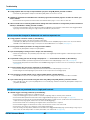
Kit Makeup
In terms of the DTX700, the term “kit” is used to refer to a collec-
tion of voices, songs, and waves assigned to the trigger input jacks
(q to !2) and the [HI-HAT CONTROL] jack (open and closed).
For added convenience, the drum trigger module comes pre-loaded
with 50 different Preset kits. You are, however, free to make your
own unique kits in whatever way you see fit, and up to 60 can also
be stored internally. And if, for whatever reason, you need to restart
your customizing from scratch, you can press the [KIT] button to
access the Kit area and then press the [F3] button (INIT KIT) to
restore the factory default settings.
Kits & Voices
Within the DTX700, voice data is grouped and stored in kit
units. In other words, each kit contains the voice-related infor-
mation for all of its pad and controller assignments. Whenever
a kit is created by editing voices, the voices themselves are not
stored within the kit; instead, the settings for all associated
parameters – such as tuning, stereo pan, attack time, release
time, effects, etc. – are stored. As you would expect, each of the
pads can have different parameter settings (see page16). There-
fore, even when the display shows the same voice assigned to
two or more pads, the sounds produced by each will not neces-
sarily be the same.
Preset songs (63)
Demo
songs (2)
Practice songs
(44)
Pad songs
(17)
Total capacity for songs (93)
Preset kits (50)
Total capacity for kits (60)
Using INIT KIT, you can
restore the factory default
settings for Preset kits.

Internal Design of the DTX700
DTX700 Reference Manual
6
Voices & Layers
The DTX700 provides four layers (A to D) for each trigger
input source. For this reason, you can assign up to four different
voices to each one. What’s more, these layered voices can also
be triggered in three different ways – for example, they will all
play together in Stack mode, a different one will be played for
each strike in Alternate mode, and they can be sustained and
turned off on each successive strike in Hold mode. (Use the
Mode parameter from the Menu area’s Kit/MIDI/Assign page
to make these settings.)
To overlay multiple voices, first of all select the trigger input
source, and use the Note parameter from the Menu area’s Kit/
MIDI/Assign page to ensure that a MIDI note number is
assigned to each of its layers. Then, use the above-mentioned
Mode parameter to set the way in which the layered voices are
to be triggered, and finally, use the VoiceCategory and Number
parameters from the Menu area’s Kit/Voice page to assign suit-
able voices to each layer.
NOTE
• When assigning a pad song to a trigger input source, only
one layer can be configured for it.
Voices and MIDI note numbers
It is important to realize that voices are actually assigned to
MIDI note numbers whenever Stack mode or Alternate mode is
used (see page21). With these modes, the sounds to be played
together are set using MIDI note numbers and not voices. To
change the correspondence between MIDI note numbers and
voices within the current kit, you can select voices assigned to
MIDI note numbers on the Menu area’s Kit/Voice page.
Effects
The effect processor built into your DTX700 applies special audio
effects to the output from the tone generator in order to modify and
enhance its sound in a wide variety of ways. Normally applied dur-
ing the final stages of editing, effects allow you optimize the sound
to better suit your own specific requirements.
Effect Processor Design
The DTX700 can apply effects to the tone generator’s output
using the following four effect units.
Variation Effect
Variation effects allow you to sculpt your sound in a variety
of different ways. A specific type of variation effect can be
selected for each kit, and you can also specify the degree to
which this effect is applied to each layer (using the
VarSend(Dry) (Variation Send Level) parameter from the
Menu area’s Kit/Voice page).
Chorus
Chorus effects change the spatial characteristics of the
sounds to which they are applied. A specific type of chorus
effect can be selected for each kit, and you can also specify
the degree to which this effect is applied to each layer (using
the ChoSend (Chorus Send Level) parameter from the Menu
area’s Kit/Voice page).
Reverb
Reverb effects add a warm ambience to sounds, simulating
the complex reflections of actual performance spaces, such
as a concert hall or a small club. A specific type of reverb
effect can be selected for each kit, and you can also specify
the degree to which this effect is applied to each layer (using
the RevSend (Reverb Send Level) parameter from the Menu
area’s Kit/Voice page).
NOTE
• The degree to which songs are processed by these effect
units can be specified using the VarSend(Dry) (Variation
Send Level) parameter, the ChoSend (Chorus Send
Level) parameter, and the RevSend (Reverb Send Level)
parameter from the Menu area’s Song/MIDI page; fur-
thermore, these settings can then be saved as part of the
corresponding song data.
Kit EQ
Supporting four-band equalization, the Kit EQ effect unit
can be configured in a different way for each kit (using the
parameters from the Menu area’s Kit/EQ page).
Master EQ
Processing the overall instrument sound just before output,
Master EQ supports three-band equalization. This effect unit
is configured using the Menu area’s Utility/Master EQ page,
and changing kits has no effect on its equalization settings.
Stack
All four layers will sound simultaneously.
Layer A
Layer B
Layer C
Layer D
Four sounds
produced together.
Alternate
Individual layers will sound sequentially.
Layer A
sounds.
Layer B
sounds.
Layer C
sounds.
Layer D
sounds.

Internal Design of the DTX700
DTX700 Reference Manual
7
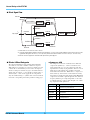
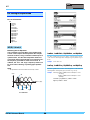
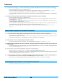
Effect Signal Flow
*1: Click-track voices cannot be sent to effects.
*2: Using the VarSend(Dry) (Variation Send Level) parameter, you can set the required balance between the amount of the
signal that will bypass the effect (i.e., the dry level) and the amount that will be sent to the effect (i.e., the wet level).
*3: Effects cannot be applied to external audio input via the [AUX IN] port.
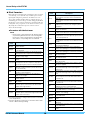
Effects & Effect Categories
The various individual effects provided by this instrument’s
effect units are sorted into a number of different categories.
What follows is a description of each category and the effects it
contains. We recommend that you refer to these descriptions
whenever setting effects. Each category’s effect table indicates
which of the effect units – i.e., Reverb (Rev), Chorus (Cho), or
Variation (Var) – can be used to apply the effect in question.
Any effect marked using a symbol can be selected and modi-
fied on the corresponding effect unit’s parameter setting pages.
Compressor & EQ
The compressor is an effect commonly used to limit and
compress the dynamics (i.e., softness or loudness) of an
audio signal. In the case of vocals, guitar parts, and other
signals that have widely varying dynamics, this effect essen-
tially squeezes the dynamic range, making soft sounds
louder and loud sounds softer. Furthermore, a compressor’s
attack and decay characteristics can be adjusted to modify
how punchy or sustained an audio signal sounds. Multi-band
compression, meanwhile, splits the input into three different
frequency bands for processing independent of each other;
accordingly, this type of effect can be thought of as combin-
ing compression with equalization.
AUX IN
Variation
Chorus
Reverb
Dry signal
Kit EQ Master EQ
RevReturn
ChoReturn
VarReturn
VarPan
ChoPan
RevPan
VarToRev
ChoToRev
VarToCho
RevSend
ChoSend
VarSend
VarSend(Wet)
VarSend(Dry)
*
1
*
3
*
2
Effect Type Var Description
Compressor
Relatively fast-acting compressor well
suited to solo performances.
MltBndComp Three-band compressor.
3 Band EQ
Three-band compressor also featuring
equalization.
Vintage EQ Vintage five-band parametric equalizer.
Enhancer
Adds higher-order harmonics to enhance a
sound’s presence.

Internal Design of the DTX700
DTX700 Reference Manual
8
Flanger & Phaser
A flanger creates a swirling, metallic sound, similar to that
of a jet plane. While this effect operates using the same
basic principles as chorus effects, it uses shorter delay times
and also incorporates feedback to produce a very distinctive
swelling sound. Rather than being used constantly through-
out a song, it is more suited to selective use in specific sec-
tions in order to add variety. A phaser, meanwhile,
introduces a phase shift into the sound being processed
before returning it to the effect input using a feedback circuit
in order to produce a characteristic animated yet mellow
tone. Gentler overall than a flanger, this effect can be put to
use in a wider range of situations, and for example, is often
used with electric pianos to sweeten their sound in a variety
of ways.
Distortion
As its name suggests, a distortion effect distorts the sound
fed into it. It produces a sound similar to that of an amplifier
turned up too high or fed with a signal that is already suffi-
ciently loud. This type of effect is widely used to add a
harsh, biting edge; furthermore, the resultant sound is char-
acterized by overall thickness and long sustain times. This
thickness comes from the large numbers of harmonics con-
tained within clipped signals. Meanwhile, the longer sustain
is not produced by the original sound being stretched; rather,
it is produced when the slowly-fading release portion that
cannot normally heard is amplified and distorted.
Wah
A wah effect dynamically changes the frequency character-
istic of a filter in order to produce a highly unique filter-
sweep sound. Auto wah changes the frequency in a cyclic
manner using an LFO, while touch wah performs filter
sweeps in response to the volume of the input signal.
Reverb
Reverb effects model the complex reverberation produced
by sounds within enclosed spaces. In this way, they add a
natural-sounding sustain, which produces a feeling of depth
and space. Furthermore, different types of reverb – such as
hall, room, plate, and stage – can be used to simulate the
sound of acoustic environments of varying sizes and con-
structions.
Effect Type Cho Var Description
SPX Flanger Produces a swirling, metallic sound.
TempoFlanger Tempo-synchronized flanger.
PhaserMono – Vintage sounding mono phaser.
PhaserStereo – Vintage sounding stereo phaser.
TempoPhaser – Tempo-synchronized phaser.
Effect Type Var Description
AmpSim 1 Guitar amp simulation.
AmpSim 2 Guitar amp simulation.
CompDist Combines compression and distortion.
CompDistDly
Combines compression, distortion, and
delay.
Effect Type Var Description
AutoWah Vintage automatic wah effect.
TouchWah Classic volume-responsive wah effect.
TouchWahDist
Touch wah with distortion applied at the
output.
Effect Type Rev Var Description
SPX Hall
Emulation of hall acoustics using an
algorithm derived from the classic
Yamaha SPX1000 Digital Multi-Effects
Processor.
SPX Room
Emulation of room acoustics using an
algorithm derived from the classic
Yamaha SPX1000 Digital Multi-Effects
Processor.
SPX Stage
Emulation of stage acoustics using an
algorithm derived from the classic
Yamaha SPX1000 Digital Multi-Effects
Processor.
R3 Hall –
Emulation of the acoustics of a con-
cert hall using an algorithm derived
from the Yamaha ProR3 – a digital
reverberator for professional-audio
applications.
R3 Room –
Emulation of room acoustics using an
algorithm derived from the above-
mentioned Yamaha ProR3.
R3 Plate –
Emulation of plate reverb using an
algorithm derived from the above-
mentioned Yamaha ProR3.
EarlyRef –
Early reflections without any subse-
quent reverberation.
GateReverb – Simulation of gated reverb.
ReverseGate –
Simulation of gated reverb played in
reverse.

Internal Design of the DTX700
DTX700 Reference Manual
9
Chorus
Chorus reproduces the sound of multiple instruments play-
ing in unison for a thicker, deeper tone. As all instruments
differ slightly from each other in terms of pitch and phase,
their playing together produces an overall sound that is
warmer and more spacious. In order to reproduce this type
of behavior, chorus effects make use of delay. Specifically, a
delayed, second version of the original signal is produced
and given a vibrato-type effect by varying its delay time over
a period of approximately one second using an LFO. When
this second version is mixed back into the original signal,
the resulting tone sounds as if multiple instruments are
being played in unison.
Tremolo & Rotary
Tremolo effects are characterized by the way in which they
modulate volume in a cyclical fashion. An auto-pan effect,
meanwhile, moves the sound from left to right in a similar
cyclical manner, and a rotary speaker effect simulates the
distinctive vibrato of rotary-type speakers often used with
organs. In a rotary speaker, the horn and rotor are spun in
order to create highly unique sounds using the Doppler
Effect.
Delay
Delay effects create a delayed version of the input signal,
and as such, they can be used for many different purposes,
such as creating a sense of spaciousness or thickening a
sound.
Miscellaneous
This category contains effect types not included in the other
categories.
Effect Type Var Cho Description
G Chorus
Rich, deep chorus with complex mod-
ulation.
2 Modulator
Chorus effect allowing pitch and
amplitude modulation to be adjusted
for a more natural, spacious tone.
SPX Chorus
Enhances modulation and spacious-
ness using a 3-phase LFO.
Symphonic
Multi-stage modulation for a wider-
sounding chorus.
Ensemble –
Modulation-free chorus achieved by
adding a slightly pitch-shifted sound.
Effect Type Var Description
AutoPan
Cyclically moves the sound between left
and right channels.
Tremolo
Cyclically modulates the volume of the pro-
cessed signal.
RotarySp Rotary speaker simulator.
Effect Type Var Description
CrossDelay
A pair of delays featuring cross-over feed-
back to produce a sound that swirls
between the left and right channels.
TempoCros-
Dly
A pair of delays with cross-over feedback
and a tempo-synchronized delay time.
TempoDly-
Mono
A single mono delay synchronized with the
instrument’s tempo.
TempoDlySt
A stereo delay synchronized with the instru-
ment’s tempo.
Delay LR
A delay with separate left and right chan-
nels.
Delay LCR
A triple delay processing left, right, and cen-
ter channels independently.
Delay LR St
A stereo delay with fully independent left
and right channels.
Effect Type Var Description
Isolator
Controls the volume of individual frequency
bands using powerful filters.
Telephone
Reproduces the sound of telephone speech
by cutting high and low frequencies.
TalkingMod
Incorporates a vowel-type formant into the
input signal.
PitchChange Changes the pitch of the input signal.

Internal Design of the DTX700
DTX700 Reference Manual
10
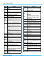
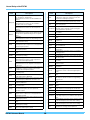
Effect Parameters
Each of the above-mentioned effects includes a range of param-
eters allowing you to adjust the way in which it processes the
input signal. Using these parameters, the behavior of each
effect can be optimized in line with, for example, the type of
sound being processed or the type of music being played. While
the function of each of these parameters is described in the fol-
lowing table, it is good practice to also listen to how they actu-
ally change the sound of the respective effect in order to
achieve the best settings.
Parameters with identical names
NOTE
• Certain effects contain parameters with identical names
yet performing different functions. In the following table,
the function of each such parameter is described sepa-
rately and the corresponding effects are identified.
Parameter
name
Descriptions
AMDepth
This parameter is used to set the depth of ampli-
tude modulation.
AmpType
This parameter is used to set the type of amplifier
to be simulated.
Attack
This parameter is used to set the amount of time
that elapses before compression is fully applied.
Bottom
*1
This parameter is used to set the lowest point in
the filter’s sweep range.
Color
*2
This parameter is used to set the fixed phase mod-
ulation.
CommonRel
This parameter is used to set the amount of time
that elapses before the compressor stops process-
ing the input signal (common for all three bands).
Compres
This parameter is used to set the input-signal level at
which the compressor starts to process the sound
(i.e., the threshold).
Cutoff
This parameter is used to set the offset value for
the filter’s control frequency.
Delay
This parameter is used to set the delay time in
terms of note lengths.
DelayC
This parameter is used to set the delay time for the
center channel.
DelayL
This parameter is used to set the delay time for the
left channel.
DelayL>R
This parameter is used to set the time that elapses
between input of sound via the left channel and
output via the right channel.
DelayR
This parameter is used to set the delay time for the
right channel.
DelayR>L
This parameter is used to set the time that elapses
between input of sound via the right channel and
output via the left channel.
Density
[Reverb effects other than EarlyRef]
This parameter is used to set the reverb density.
[Early Ref]
This parameter is used to set the density of early
reflections.
Depth
This parameter is used to set the amplitude of the
LFO wave that controls cyclic changes in phase
modulation.
Detune
This parameter is used to set the degree to which
pitches are detuned.
Device
This parameter is used to select one of a number
of devices that distort the sound in different ways.
Diffuse
[TempoPhaser and EarlyRef]
This parameter is used to adjust the spaciousness
of the sound produced.
[Reverb effects other than EarlyRef]
This parameter is used to set how wide the reverb
sounds.
Directn
This parameter is used to set the direction of enve-
lope-follower modulation.
Div.FreqH
This parameter is used to set the mid-high fre-
quency when splitting the sound into three bands.
Div.FreqL
This parameter is used to set the low-mid fre-
quency when splitting the sound into three bands.
DlyLvlC
This parameter is used to set the delay volume for
the center channel.
DlyMix
This parameter is used to set the mixing level for
the delayed sound.
DlyOfst
This parameter is used to set the modulation delay
time’s offset value.
Drive
This parameter is used to set the degree to which
the effect is applied.
DriveHorn
This parameter is used to set the depth of modula-
tion produced through rotation of the high-fre-
quency horn.
DriveRotor
This parameter is used to set the depth of modula-
tion produced through rotation of the low-frequency
rotor.
DstL.Gain
This parameter is used to set the degree by which
the low frequencies from the distorted sound are
boosted or cut.
DstM.Gain
This parameter is used to set the degree by which
the mid frequencies from the distorted sound are
boosted or cut.
Edge
This parameter is used to specify a curve that
determines how the sound is distorted.
EQ1Freq
This parameter is used to set the cutoff frequency
for the EQ1 band (i.e., low shelving).
EQ1Gain
This parameter is used to set the gain for the EQ1
band (i.e., low shelving).
EQ2Freq
This parameter is used to set the center frequency
for the EQ2 band.
EQ2Gain
This parameter is used to set the gain for the EQ2
band.
EQ2Q
This parameter is used to set the resonance of the
EQ2 band.
EQ3Freq
This parameter is used to set the center frequency
for the EQ3 band.
EQ3Gain
This parameter is used to set the gain for the EQ3
band.
Parameter
name
Descriptions
*1: The Bottom parameter’s setting is valid only when less than that
of the Top parameter.
*2: The Color parameter’s setting has no effect with certain combi-
nations of Mode and Stage settings.

Internal Design of the DTX700
DTX700 Reference Manual
11
EQ3Q
This parameter is used to set the resonance of the
EQ3 band.
EQ4Freq
This parameter is used to set the center frequency
for the EQ4 band.
EQ4Gain
This parameter is used to set the gain for the EQ4
band.
EQ4Q
This parameter is used to set the resonance of the
EQ4 band.
EQ5Freq
This parameter is used to set the cutoff frequency
for the EQ5 band (i.e., high shelving).
EQ5Gain
This parameter is used to set the gain for the EQ5
band (i.e., high shelving).
ER/Rev
This parameter is used to set the relative volumes
of early reflections and reverberation.
F/RDpth
This parameter is used to set the front-to-rear pan
depth (and is valid only when PanDirectn is set to
“Lturn” or “Rturn”).
FBHiDmp
This parameter is used to set how the feedback
sound decays in the high-frequency band (with
smaller values corresponding to faster decay).
FBLevel
[Chorus effects, Delay effects, and TempoFlanger]
This parameter is used to set how much of the
delay sound is fed back into the effect’s input (with
negative values indicating that its phase is to be
inverted).
[TempoPhaser]
This parameter is used to set how much of the
phaser’s output is fed back into its input (with nega-
tive values indicating that its phase is to be
inverted).
[Reverb effects]
This parameter is used to set the initial delay’s feed-
back level.
FBLvl1
This parameter is used to set the feedback level for
the first delay sound.
FBLvl2
This parameter is used to set the feedback level for
the second delay sound.
FBTime
This parameter is used to set the feedback delay
time.
FBTime1
This parameter is used to set the delay time for
feedback delay 1.
FBTime2
This parameter is used to set the delay time for
feedback delay 2.
FBTimeL
This parameter is used to set the delay time for the
left feedback delay.
FBTimeR
This parameter is used to set the delay time for the
right feedback delay.
Feedback
This parameter is used to set how much of the
effect’s output is fed back into its input.
Fine1
This parameter is used to adjust the first fine-pitch
setting.
Fine2
This parameter is used to adjust the second fine-
pitch setting.
H.Freq
This parameter is used to set the center frequency
of the high-frequency EQ band.
H.Gain
This parameter is used to set the amount by which
the high-frequency EQ band is boosted or cut.
Height
This parameter is used to set the height of the simu-
lated room.
Parameter
name
Descriptions
HiAtk
This parameter is used to set the amount of time
that elapses before compression is fully applied in
the high-frequency band.
HiGain
This parameter is used to set the output level of the
high-frequency band.
HiLvl
This parameter is used to set the high-frequency
level.
HiMute
This parameter is used to activate and deactivate
high-frequency muting.
HiRat
[MltBndComp]
This parameter is used to set the compression
ratio for the high-frequency band.
[Reverb effects]
This parameter is used to adjust the high-fre-
quency component.
HiTh
This parameter is used to set the input-signal level
at which the compressor starts to process the
sound in the high-frequency band.
HornF
This parameter is used to set the speed of rotation
of the high-frequency horn at the “fast” setting.
HornS
This parameter is used to set the speed of rotation
of the high-frequency horn at the “slow” setting.
HPF
This parameter is used to set the high-pass filter’s
cutoff frequency.
InitDly
This parameter is used to set the amount of time
that elapses before early reflections are produced.
InitDly1
This parameter is used to set the delay time for the
first delay.
InitDly2
This parameter is used to set the delay time for the
second delay.
InitDlyL
This parameter is used to set the delay time for the
left-channel delay.
InitDlyR
This parameter is used to set the delay time for the
right-channel delay.
InpMode
This parameter is used to switch between mono
and stereo input.
InpSelect This parameter is used to select an input.
L.Freq
This parameter is used to set the center frequency
of the low-frequency EQ band.
L.Gain
This parameter is used to set the amount by which
the low-frequency EQ band is boosted or cut.
L/RDiffuse
This parameter is used to set the difference
between left and right delay times in order to pro-
duce a more spacious sound.
L/RDpth
This parameter is used to set the depth of the left-
right panning effect.
Lag
This parameter is used to set a time lag for delay
times specified in terms of note lengths.
LFODpth
[SPX Flanger, TempoFlanger, SPX Chorus, and
Symphonic]
This parameter is used to set the depth of modula-
tion.
[Tempo Phaser]
This parameter is used to set the depth of phase
modulation.
LFODiff
This parameter is used to set the left-right phase
difference between modulation waveforms.
Parameter
name
Descriptions

Internal Design of the DTX700
DTX700 Reference Manual
12
LFOSpeed
[TempoFlanger, G Chorus, 2 Modulator, SPX Cho-
rus, Symphonic, and Tremolo]
This parameter is used to set the modulation fre-
quency.
[TempoPhaser]
This parameter is used to set the modulation
speed in terms of note lengths.
[AutoPan]
This parameter is used to set the auto-pan fre-
quency.
LFOWave
[AutoWah]
This parameter is used to specify whether the filter-
sweep effect is produced using a sine or square
wave.
[AutoPan]
This parameter is used to set the panning curve.
Livenss
This parameter is used to set the way in which
early reflections decay.
LowAtk
This parameter is used to set the amount of time
that elapses before compression is fully applied in
the low-frequency band.
LowGain
This parameter is used to set the output level of the
low-frequency band.
LowLvl
This parameter is used to set the low-frequency
level.
LowMute
This parameter is used to activate and deactivate
low-frequency muting.
LowRat
[MltBndComp]
This parameter is used to set the compression
ratio for the low-frequency band.
[Reverb effects]
This parameter is used to adjust the low-frequency
component.
LowTh
This parameter is used to set the input-signal level
at which the compressor starts to process the
sound in the low-frequency band.
LPF
This parameter is used to set the low-pass filter’s
cutoff frequency.
M.Freq
This parameter is used to set the center frequency
of the mid-frequency EQ band.
M.Gain
This parameter is used to set the amount by which
the mid-frequency EQ band is boosted or cut.
M.Width
This parameter is used to set the width of the mid-
frequency EQ band.
Manual
This parameter is used to set the phase-modula-
tion offset value.
MicAngl
This parameter is used to set the left-right inclina-
tion of the microphone used to capture the
speaker’s output.
MidAtk
This parameter is used to set the amount of time that
elapses before compression is fully applied in the
mid-frequency band.
MidGain
This parameter is used to set the output level of the
mid-frequency band.
MidLvl
This parameter is used to set the mid-frequency
level.
MidMute
This parameter is used to activate and deactivate
mid-frequency muting.
MidRat
This parameter is used to set the compression
ratio for the mid-frequency band.
Parameter
name
Descriptions
MidTh
This parameter is used to set the input-signal level
at which the compressor starts to process the
sound in the mid-frequency band.
MixLvl
This parameter is used to set how much of the
effect sound is mixed back into the dry sound.
Mode
This parameter is used to adjust the mode of oper-
ation of the phaser.
MoveSpeed
This parameter is used to specify the amount of
time that elapses until the sound set using the
Vowel parameter is produced.
On/Off
This parameter is used to activate and deactivate
the isolator.
OutLvl This parameter is used to set the output level.
OutLvl1
This parameter is used to set the first-stage output
level.
OutLvl2
This parameter is used to set the second-stage
output level.
Output This parameter is used to set the output level.
OverDr
This parameter is used to adjust the way in which
the sound distorts.
Pan1
This parameter is used to set the first stereo-pan-
ning position.
Pan2
This parameter is used to set the second stereo-
panning position.
PanDirectn This parameter is used to set the auto-pan type.
PhShiftOfst
This parameter is used to set the phase-modula-
tion offset value.
Pitch1
This parameter is used to set the first pitch in semi-
tone units.
Pitch2
This parameter is used to set the second pitch in
semi-tone units.
PMDepth
This parameter is used to set the depth of pitch
modulation.
Presenc
Often seen on guitar amplifiers and the like, this
parameter is used to control the high-frequency
band.
Ratio
This parameter is used to set the compression
ratio.
Release
This parameter is used to set the amount of time
that elapses until the sound is no longer being
compressed.
Resonance
This parameter is used to set the resonance of the
filter.
ResoOfst
This parameter is used to set the resonance offset
value.
RevDly
This parameter is used to set the interval between
early reflections and subsequent reverberation.
RevTime This parameter is used to set the reverb time.
RoomSize This parameter is used to set the size of the room.
Rotor/Horn
This parameter is used to set the relative volumes
of the high-frequency horn and the low-frequency
rotor.
RotorF
This parameter is used to set the speed of rotation
of the low-frequency rotor at the “fast” setting.
RotorS
This parameter is used to set the speed of rotation
of the low-frequency rotor at the “slow” setting.
Sens
This parameter is used to set how sensitive the
wah filter is to changes in the input level.
Parameter
name
Descriptions

Internal Design of the DTX700
DTX700 Reference Manual
13
*3: The Top parameter’s setting is valid only when equal to or
greater than that of the Bottom parameter.
DTX700 Internal Memory
By storing kits, songs, and waves that you have created and edited
in the DTX700’s internal memory, you ensure that they will be
always available for use, even after the instrument has been turned
off. In addition, trigger setups and the settings from the Menu
area’s Utility pages can also be stored in memory for reuse.
Data Retained by the DTX700
The following types of setting data can be stored in the
DTX700’s internal memory.
•Kits
• Songs
•Waves
• Trigger setups
• Other utility settings
NOTE
• Whenever data files are saved and loaded or waves and
MIDI files are imported, the corresponding data is automati-
cally stored in memory. Settings cannot be stored for a cer-
tain number of parameters.
Saving & Loading Data Files
All of the above-mentioned items of data that can be stored in
the DTX700’s internal memory can also be saved as files on a
USB storage device. Whenever needed, furthermore, these
memory files can be loaded back into the drum trigger module
from the storage device. For details, see the description of the
File pages from the Menu area (see page57).
S-FTmHorn
This parameter is used to set how long it takes for
the high-frequency horn to switch between fast and
slow rotation speeds.
S-FTmRotor
This parameter is used to set how long it takes for
the low-frequency rotor to switch between fast and
slow rotation speeds.
Speaker
This parameter is used to select the type of
speaker to be simulated.
Speed
[PhaserMono and PhaserStereo]
This parameter is used to set the frequency of the
LFO that controls cyclic changes in phase modula-
tion.
[AutoWah]
This parameter is used to set the LFO speed.
SpeedCtrl
This parameter is used to set the rotation speed as
“fast” or “slow”.
Spread
This parameter is used to set how wide the effect’s
output sounds.
Stage
This parameter is used to set the number of phase-
filter steps.
Thresh
This parameter is used to set the input-signal level
at which the effect starts to process the sound.
To p
*3
This parameter is used to set the highest point in
the filter’s sweep range.
Ty pe
[Wah effects]
This parameter is used to set the wah-effect type.
[EarlyRef, GateReverb, and ReverseGate]
This parameter is used to set the reflected-sound
type.
Vowel This parameter is used to select a vowel type.
Parameter
name
Descriptions

DTX700 Reference Manual 14
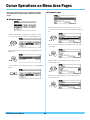
Cursor Operations on Menu Area Pages
The way in which the cursor is displayed and oper-
ated on Menu area pages differs from that of other
pages.
Navigation pages
When you turn the dial on navigation-type pages, the cursor
(i.e., the inverted text) moves in the corresponding direction.
By pressing the dial, you can move one level further into the
Menu area.
To move back one step towards the top page, press the [EXIT]
button.
Parameter pages
When you turn the dial on parameter-type pages, the cursor
(i.e., the inverted text) moves up and down within the displayed
list.
When you press the dial, the cursor will zoom in on the value
on the right.
In this condition, you can turn the dial to change the value
selected by the cursor.
When you press the dial again, the cursor will zoom out to
select the entire row.

DTX700 Reference Manual 15
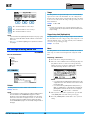
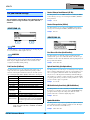
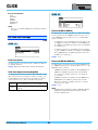
KIT
: The current kit number is reduced by 1.
: The current kit number is increased by 1.
: The current kit number is locked.
NOTE
• If you hold down the [SHIFT] button and press the [F1] or [F2]
button, the current kit number will be reduced or increased in
units of 10.
• See page 14 for details regarding cursor operations on Menu
area pages.
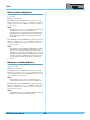
KIT/COMMON
List of Functions
Volume
Use this parameter to set the volume of the entire kit.
Settings: 0 to 127
NOTE
• If you change the Volume parameter setting for MIDI channel
10 on the Menu area’s Kit/MIDI/Other page, the Volume
parameter on this page will be automatically set to the same
value. The reverse does not apply, however – in other words,
the Volume parameter for MIDI channel 10 from the Menu
area’s Kit/MIDI/Other page is not affected by changes made on
this page.
Tempo
Use this parameter to specify the tempo to be set automatically
upon selection of the current drum kit. An “off” setting means
that the tempo will not change automatically when the current kit
is selected – in other words, the tempo of the previously selected
kit is maintained.
Settings: off, 30 to 300
NOTE
• If waves are assigned to any of the kit’s pads, the tempo (or
speed) at which they are played will not be affected by the kit’s
tempo setting.
Trigger Setup Link (TrgSetupLink)
Use this parameter to specify the trigger setup to be used when
the current kit is selected. A trigger setup can be assigned to each
different drum kit. Select “off” if the currently selected drum kit
does not need a special trigger setup.
Settings: off, 1 to 20
Name
Use this parameter to set a name for the currently-selected kit. A
name of up to 12 characters in length can be assigned to drum
kits.
Setting a Kit Name
1. Press the dial to call up the kit naming page.
2. Move the cursor within the name field using the [F1] and
[F3] buttons and select a character for that position by
turning the dial or pressing the [-/DEC] and [+/INC] but-
tons. The following characters can be used.
NOTE
• If you hold down the [SHIFT] button and press the [F1]
or [F3] button, the cursor will move to the start or end of
the kit name field.
• If you hold down the [SHIFT] button and press the [-/
DEC] or [+/INC] button, or alternatively, hold down the
[SHIFT] button and turn the dial, the cursor will jump
between the “ ”, “0”, “A”, “a”, and “~” characters.
3. When you have entered the required name, press the dial
or the [EXIT] button to return to the previous page.
4. Press the [STORE] button and the dial to store your new
setting.
For settings affecting entire kits
KIT/COMMON
Common
Volume
Tempo
TrgSetupLink
Name
Icon

KIT
DTX700 Reference Manual
16
Icon
An artist’s impression of what the current kit might look like can
be displayed on the right of the Kit page (accessed using the
[KIT] button). Using the Icon parameter, you can change the
illustration used for the kit. In addition, you can also select “off”
to display no icon.
Settings: Acoustic, Rock, Electric, Percuss, RhythmBox, Effect,
R&B/H-HOP, PadSong, off
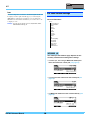
KIT/VOICE
List of Functions
The makeup of the Kit/Voice page depends on the
currently selected voice among other settings.
• If a voice (i.e., not a song or MIDI note number) has
been selected for the current pad (see page17):
• If a song has been selected for the current pad (see
page17):
• If a MIDI note number has been selected directly (see
page18):
For voice-related settings
KIT/VOICE 1/6
Voice
VoiceCategory
VoiceNumber
Tune
Note
Volume
Pan
Attack
Decay
Release
Filter
Q
VarSend(Dry)
ChoSend
RevSend
Mono/Poly
AltGroup
SliderSelect

KIT
DTX700 Reference Manual
17
[Page displayed when a voice has been selected
for the current pad]
q Current pad
This indicates the pad for which voice settings are being made.
You can change the current pad either by hitting a different one or
by pressing the [F1] button (PAD) to open the popup window and
turning the dial to make a selection.
PAD
This button is used to select the current pad. When pressed, a
popup window will appear, and you can then turn the dial to
change the pad. Press the [EXIT] button to return from the popup
window. You can also strike a pad to select it. Instead of selecting
a pad, meanwhile, you can specify a MIDI note number directly.
Settings: SnareHd, SnareOp, SnareCl, SnrHdOff, SnrOpOff,
Snr C l O ff, To m 1 H d , To m 1 R m 1 , To m 1 R m 2 , To m 2 H d ,
Tom2Rm1, Tom2Rm2, Tom3Hd, Tom3Rm1, Tom3Rm2,
RideBw, RideEg, RideCp, Crash1Bw, Crash1Eg,
Crash1Cp, Crash2Bw, Crash2Eg, Crash2Cp, HHBwOp,
HHEgOp, HHBwCl, HHEgCl, HHFtCl, HHSplsh, Kick,
Pad10, Pad11Hd, Pad11Rm1, Pad11Rm2, HHKick, C#-1
to A#5
+ PAD LOCK
This button combination is used to fix the pad indicated by q.
This means that you can play other pads without changing the
current selection.
LAYER
This button is used to select the layer you wish to set. Each pad
comprises up to four layers, each of which can be used to play a
different voice.
NOTE
• On this page, layers can be selected for a pad only when a
MIDI note number has been assigned to more than one of
them using the Note parameter from the Menu area’s Kit/MIDI/
Assign page.
AUDITION
This button can be pressed to hear the set voice without having to
play the pad.
VoiceCategory
Use this parameter to specify the category from which a voice
will be assigned. In addition, you can also indicate that a song or
wave is to be assigned.
Settings: Kick, Snare1, Snare2, Tom1, Tom2, Cymbal, Hi-Hat, Lat-
inPerc, AsiaPerc, AfrcArbcPerc, OrchPerc,
ElectricPerc, EFX, Melody, Wave, e Song
VoiceNumber
Use this parameter to specify the number of the voice to be
assigned.
[Page displayed when a song has been selected
for the current pad]
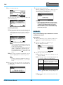
PLAYMODE (Song Playback Mode)
This button is used to set a playback mode when a song has been
assigned to the current pad.
NOTE
• Up to three songs can be played simultaneously.
• If the VoiceCategory parameter is set to “eSong”, no other pan-
els will be displayed for this page.
q
Play: The song will start playing from the begin-
ning.
Chase: One successive measure of the song will
be played each time you strike the pad.
Cut-off: Only one song set to this mode can play
at any time. In other words, whenever a cut-off
mode song is triggered, any other song already
playing in this mode will be automatically
stopped.

KIT
DTX700 Reference Manual
18
[Page displayed when a MIDI note number has
been selected directly using the [F1] button (PAD)]
NOTE
• The VoiceCategory parameter cannot be set to “eSong” when
a MIDI note number is selected directly.
The parameter used for tuning will depend on the
type of voice assigned to the current pad.
[Drum sounds or waves (i.e., imported audio files)]
[When VoiceCategory is “Melody”]
Tuning (Tune)
Use this parameter to adjust the tuning of the assigned voice in
one-cent steps (0.01 = 1 cent)
Settings: -24.00 to +0.00 to +24.00
NOTE
• A cent is a unit of pitch defined as one hundredth of a semi-
tone. (100 cents = 1 semitone)
Note
Use this parameter to set the pitch of the assigned voice as a
MIDI note number.
Settings: C-2 to G8
Volume
Use this parameter to set the volume of the voice.
Settings: 0 to 127
Voice Panorama (Pan)
Use this parameter to set the stereo pan of the voice.
Settings: L63 to C to R63
The following parameters are used to adjust the tone
of the voice.
Attack Time (Attack)
Use this parameter to set the amount of time it takes from when
the pad is struck until the assigned voice reaches its peak volume.
Settings: -64 to +0 to +63
Decay Time (Decay)
Use this parameter to set the amount of time it takes the voice to
drop to a steady level after reaching its peak level.
Settings: -64 to +0 to +63
Release Time (Release)
Use this parameter to set the amount of time it takes for the voice
to fade out after sending a MIDI Note Off message.
Settings: -64 to +0 to +63
NOTE
• MIDI Note Off messages are not sent for pads and layers for
which the RcvKeyOff (Receive Key Off) parameter from the
Menu area’s Kit/MIDI/Assign page is set to “off”. Therefore, the
release-time setting has no effect in such a case.
• With certain types of voices, modifying the tone parameters
above will have very little effect.
KIT/VOICE 2/6
KIT/VOICE 3/6

KIT
DTX700 Reference Manual
19
Filter Cutoff Frequency (Filter)
Use this parameter to set a cutoff frequency for the low-pass fil-
ter. Frequencies above this level will be removed from the
selected voice.
Settings: -64 to +0 to +63
Filter Resonance (Q)
Use this parameter to change the timbre of the voice by boosting
frequencies around the cutoff frequency.
Settings: -64 to +0 to +63
Using the following parameters, you can adjust the
degree to which the DTX700’s built-in variation, cho-
rus, and reverb effects are applied to individual
voices.
Variation Send Level (VarSend(Dry))
Use this parameter to specify how much of the sound produced
by the voice will be sent to the variation effect. (The dry level is
shown in parentheses.)
Settings: 0 to 127
NOTE
• If layers have been set for the current voice, you can set a
send level for each one.
Chorus Send Level (ChoSend)
Use this parameter to specify how much of the sound produced
by the voice will be sent to the chorus effect.
Settings: 0 to 127
NOTE
• The chorus send level for the entire kit can be adjusted using
the ChoSend (Chorus Send Level) parameter from the Menu
area’s Kit/Effect/Mixer page.
• If layers have been set for the current voice, you can set a
send level for each one.
Reverb Send Level (RevSend)
Use this parameter to specify how much of the sound produced
by the voice will be sent to the reverb effect.
Settings: 0 to 127
NOTE
• The reverb send level for the entire kit can be adjusted using
the Reverb Send Level (RevSend) parameter from the Menu
area’s Kit/Effect/Mixer page.
• If layers have been set for the current voice, you can set a
send level for each one.
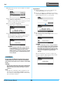
Polyphony (Mono/Poly)
Use this parameter to specify how overlapping sounds from the
same pad will be treated.
Settings: mono, poly
KIT/VOICE 4/6
KIT/VOICE 5/6
KIT/VOICE 6/6
mono
When two overlapping sounds are produced by
striking the same pad, the latter sound is given pri-
ority and the earlier sound is silenced.
poly
No such restriction applies and all overlapping
sounds are output.

KIT
DTX700 Reference Manual
20
Alternate Group (AltGroup)
Use this parameter to assign voices to alternate groups (i.e.,
monophonic sets of pads, only one of which can be producing a
sound at any time). If you do not want various individual voices
to be played together, they should be assigned to the same alter-
nate group. Whenever voices from the same alternate group are
triggered by playing the pads, the latter voice is given priority and
the earlier one is silenced. Set this parameter to “off” if you do
not want to assign to an alternate group.
Settings: off, hhOpen, hhClose, 1 to 124
NOTE
• The “hhOpen” and “hhClose” alternate groups operate in a
special way: If a voice from the “hhClose” group is triggered
after a voice from the “hhOpen” group, the hhOpen voice is
silenced and only the hhClose voice is played. No silencing of
the earlier sound is performed for any other triggering
sequence (for example, hhOpen followed by hhOpen; hhClose
followed by hhOpen; or hhClose followed by hhClose).
SliderSelect
Use this parameter to select the slider for controlling the volume
of the current pad’s voices.
Settings: kick, snare, tom, cymbal, hihat, no asg (selected when
no assignment is required)
KIT/MIDI
List of Functions
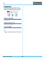
MessageType
Use this parameter to set the type of MIDI message that will be
sent whenever the current pad is struck.
For MIDI-related settings
KIT/MIDI/ASSIGN 1/5
note
A MIDI note will be sent. Use this setting if you wish
to produce a sound by striking the pad.
CC A Control Change message will be sent.
PC A Program Change message will be sent.
start
A sysex Start command (hexadecimal FA) will be
sent.
continue
A sysex Continue command (hexadecimal FB) will
be sent.
stop
A sysex Stop command (hexadecimal FC) will be
sent.
MIDI
Assign
MessageType
Mode
Note
MIDI Ch
GateTime
RcvKeyOff
TrgLink
MaskTime
VelLimitLo
VelLimitHi
VelCrossFade
TrgVel
TrgMonoPoly
Trg Al t G rp
TG MIDI Sw
TG Switch
MIDI Switch
Other
Transmit
Volume
Pan
MSB
LSB
PC
VarSend(Dry)
ChoSend
RevSend
CC No
CC Val
Sayfa yükleniyor ...
Sayfa yükleniyor ...
Sayfa yükleniyor ...
Sayfa yükleniyor ...
Sayfa yükleniyor ...
Sayfa yükleniyor ...
Sayfa yükleniyor ...
Sayfa yükleniyor ...
Sayfa yükleniyor ...
Sayfa yükleniyor ...
Sayfa yükleniyor ...
Sayfa yükleniyor ...
Sayfa yükleniyor ...
Sayfa yükleniyor ...
Sayfa yükleniyor ...
Sayfa yükleniyor ...
Sayfa yükleniyor ...
Sayfa yükleniyor ...
Sayfa yükleniyor ...
Sayfa yükleniyor ...
Sayfa yükleniyor ...
Sayfa yükleniyor ...
Sayfa yükleniyor ...
Sayfa yükleniyor ...
Sayfa yükleniyor ...
Sayfa yükleniyor ...
Sayfa yükleniyor ...
Sayfa yükleniyor ...
Sayfa yükleniyor ...
Sayfa yükleniyor ...
Sayfa yükleniyor ...
Sayfa yükleniyor ...
Sayfa yükleniyor ...
Sayfa yükleniyor ...
Sayfa yükleniyor ...
Sayfa yükleniyor ...
Sayfa yükleniyor ...
Sayfa yükleniyor ...
Sayfa yükleniyor ...
Sayfa yükleniyor ...
Sayfa yükleniyor ...
Sayfa yükleniyor ...
Sayfa yükleniyor ...
Sayfa yükleniyor ...
Sayfa yükleniyor ...
Sayfa yükleniyor ...
Sayfa yükleniyor ...
Sayfa yükleniyor ...
Sayfa yükleniyor ...
-
 1
1
-
 2
2
-
 3
3
-
 4
4
-
 5
5
-
 6
6
-
 7
7
-
 8
8
-
 9
9
-
 10
10
-
 11
11
-
 12
12
-
 13
13
-
 14
14
-
 15
15
-
 16
16
-
 17
17
-
 18
18
-
 19
19
-
 20
20
-
 21
21
-
 22
22
-
 23
23
-
 24
24
-
 25
25
-
 26
26
-
 27
27
-
 28
28
-
 29
29
-
 30
30
-
 31
31
-
 32
32
-
 33
33
-
 34
34
-
 35
35
-
 36
36
-
 37
37
-
 38
38
-
 39
39
-
 40
40
-
 41
41
-
 42
42
-
 43
43
-
 44
44
-
 45
45
-
 46
46
-
 47
47
-
 48
48
-
 49
49
-
 50
50
-
 51
51
-
 52
52
-
 53
53
-
 54
54
-
 55
55
-
 56
56
-
 57
57
-
 58
58
-
 59
59
-
 60
60
-
 61
61
-
 62
62
-
 63
63
-
 64
64
-
 65
65
-
 66
66
-
 67
67
-
 68
68
-
 69
69


Yamaha DTX700 Kullanım kılavuzu
- Kategori
- Müzik davulları
- Tip
- Kullanım kılavuzu
Diğer dillerde
- español: Yamaha DTX700 Manual de usuario
- français: Yamaha DTX700 Manuel utilisateur
- italiano: Yamaha DTX700 Manuale utente
- svenska: Yamaha DTX700 Användarmanual
- čeština: Yamaha DTX700 Uživatelský manuál
- polski: Yamaha DTX700 Instrukcja obsługi
- Deutsch: Yamaha DTX700 Benutzerhandbuch
- português: Yamaha DTX700 Manual do usuário
- English: Yamaha DTX700 User manual
- dansk: Yamaha DTX700 Brugermanual
- русский: Yamaha DTX700 Руководство пользователя
- suomi: Yamaha DTX700 Ohjekirja
- Nederlands: Yamaha DTX700 Handleiding
- română: Yamaha DTX700 Manual de utilizare