Yamaha NS-SW500 El kitabı
- Kategori
- Hoparlörler
- Tip
- El kitabı
Bu kılavuz aynı zamanda aşağıdakiler için de uygundur:


i En
Thank you for selecting this YAMAHA product.
Please read the following operating precautions before use.
YAMAHA will not be held responsible for any damage and/or
injury caused by not following the cautions below.
• To assure the finest performance, please read this manual
carefully. Keep it in a safe place for future reference.
• Install this unit in a cool, dry, clean place - away from
windows, heat sources, sources of excessive vibration, dust,
moisture and cold. Avoid sources of humming
(transformers, motors). To prevent fire or electrical shock,
do not expose this unit to rain or water.
• The voltage to be used must be the same as that specified on
the rear panel. Using this unit with a higher voltage than
specified is dangerous and may cause a fire and/or electric
shock.
• Do not use force on switches, controls or connection wires.
When moving the unit, first disconnect the power plug and
the wires connected to other equipment. Never pull the
wires themselves.
• When not planning to use this unit for a long period (ie., vacation,
etc.), disconnect the AC power plug from the wall outlet.
• To prevent lightning damage, disconnect the AC power plug
when there is an electric storm.
• Since this unit has a built-in power amplifier, heat will
radiate from the rear panel. Place the unit apart from the
walls, allowing at least 20 cm of space above, behind and on
both sides of the unit to prevent fire or damage.
Furthermore, do not position with the rear panel facing
down on the floor or other surfaces.
• Do not cover the rear panel of this unit with a newspaper, a
tablecloth, a curtain, etc., in order not to obstruct heat
radiation. If the temperature inside the unit rises, it may
cause fire, damage to the unit and/or personal injury.
• Do not place the following objects on this unit:
- Glass, china, small metallic, etc.
If glass, etc., falls as a result of vibrations and breaks, it
may cause bodily injury.
- A burning candle etc.
If the candle falls as a result of vibration, it may cause fire
and bodily injury.
- A vessel containing water
If the vessel falls as a result of vibration and water spills,
it may cause damage to the speaker, and/or you may get an
electric shock.
• Do not place this unit where foreign material, such as
dripping water. It might cause fire, damage to this unit, and/
or personal injury.
• Never put a hand or a foreign object into the YST port
located on the right side of this unit. When moving this unit,
do not hold the port, as it might cause personal injury and/or
damage to this unit.
• Never place a fragile object near the YST port of this unit. If
the object falls or drops as a result of the air pressure, it may
cause damage to the unit and/or personal injury.
• Never open the cabinet. It might cause an electric shock,
since this unit uses a high voltage. It might also cause
personal injury and/or damage to this unit. If something
drops into the set, contact your dealer.
• When using a humidifier, be sure to avoid condensation
inside this unit by allowing enough space around this unit or
avoiding excess humidification. Condensation might cause
fire, damage to this unit, and/or electric shock.
• Super-bass frequencies reproduced by this unit may cause a
turntable to generate a howling sound. In such a case, move
this unit away from the turntable.
• This unit may be damaged if certain sounds are
continuously output at high volume level. For example, if
20 Hz-50 Hz sine waves from a test disc, bass sounds from
electronic instruments, etc., are continuously output, or
when the stylus of a turntable touches the surface of a disc,
reduce the volume level to prevent this unit from being
damaged.
• If you hear distortion (i.e., unnatural, intermittent “rapping” or
“hammering” sounds) coming from this unit, reduce the volume
level. Extremely loud playing of a movie soundtrack’s low
frequency, bass-heavy sounds or similarly loud popular music
passages can damage this speaker system.
• Vibration generated by super-bass frequencies may distort
images on a TV. In such a case, move this unit away from
the TV set.
• Do not attempt to clean this unit with chemical solvents as
this might damage the finish. Use a clean, dry cloth.
• Be sure to read the “TROUBLESHOOTING” section
regarding common operating errors before concluding that
the unit is faulty.
• Install this unit near the wall outlet and where the AC power
plug can be reached easily.
• Secure placement or installation is the owner’s
responsibility. YAMAHA shall not be liable for any
accident caused by improper placement or installation
of speakers.
• VOLTAGE SELECTOR
(Asia and General models only)
The voltage selector switch on the rear panel of this unit
must be set to your local main voltage BEFORE
plugging this unit into the AC main supply. Voltages are
110-120 V/220-240 V.
For U.K. customers
If the socket outlets in the home are not suitable for the plug supplied
with this appliance, it should be cut off and an appropriate 3 pin plug
fitted. For details, refer to the instructions described below.
Note: The plug severed from the mains lead must be destroyed, as
a plug with bared flexible cord is hazardous if engaged in a live
socket outlet.
SPECIAL INSTRUCTIONS FOR U.K. MODEL
CAUTION: Read this before operating your unit
WARNING
TO REDUCE THE RISK OF FIRE OR ELECTRIC SHOCK, DO
NOT EXPOSE THIS APPLIANCE TO RAIN OR MOISTURE.
This unit is not disconnected from the AC power source as
long as it is connected to the wall outlet, even if this unit
itself is turned off. In this state, this unit is designed to
consume a very small quantity of power.
IMPORTANT:
THE WIRES IN MAINS LEAD ARE COLOURED IN
ACCORDANCE WITH THE FOLLOWING CODE:
Blue: NEUTRAL
Brown: LIVE
As the colours of the wires in the mains lead of this apparatus
may not correspond with the coloured markings identifying
the terminals in your plug, proceed as follows: The wire
which is coloured BLUE must be connected to the terminal
which is marked with the letter N or coloured BLACK. The
wire which is coloured BROWN must be connected to the
terminal which is marked with the letter L or coloured RED.
Make sure that neither wire is connected to the earth terminal
of a three pin plug.

ii En
English
Limited Guarantee for European Economic
Area (EEA) and Switzerland
Thank you for having chosen a Yamaha product. In the unlikely event that
your Yamaha product needs guarantee service, please contact the dealer
from whom it was purchased. If you experience any difficulty, please
contact Yamaha representative office in your country. You can find full
details on our website (http://www.yamaha-hifi.com/ or http://
www.yamaha-uk.com/ for U.K. resident).
The product is guaranteed to be free from defects in workmanship or
materials for a period of two years from the date of the original purchase.
Yamaha undertakes, subject to the conditions listed below, to have the
faulty product or any part(s) repaired, or replaced at Yamaha’s discretion,
without any charge for parts or labour. Yamaha reserves the right to replace
a product with that of a similar kind and/or value and condition, where a
model has been discontinued or is considered uneconomic to repair.
Conditions
1. The original invoice or sales receipt (showing date of purchase, product
code and dealer’s name) MUST accompany the defective product,
along with a statement detailing the fault. In the absence of this clear
proof of purchase, Yamaha reserves the right to refuse to provide free
of charge service and the product may be returned at the customer’s
expense.
2. The product MUST have been purchased from an AUTHORISED
Yamaha dealer within the European Economic Area (EEA) or
Switzerland.
3. The product must not have been the subject of any modifications or
alterations, unless authorised in writing by Yamaha.
4. The following are excluded from this guarantee:
a. Periodic maintenance and repair or replacement of parts due to
normal wear and tear.
b. Damage resulting from:
(1) Repairs performed by the customer himself or by an unauthorised
third party.
(2) Inadequate packaging or mishandling, when the product is in
transit from the customer. Please note that it is the customer’s
responsibility to ensure the product is adequately packaged when
returning the product for repair.
(3)
Misuse, including but not limited to (a) failure to use the product
for its normal purpose or in accordance with Yamaha’s instructions
on the proper use, maintenance and storage, and (b) installation or
use of the product in a manner inconsistent with the technical or
safety standards in force in the country where it is used.
(4) Accidents, lightning, water, fire, improper ventilation, battery
leakage or any cause beyond Yamaha’s control.
(5) Defects of the system into which this product is incorporated and/
or incompatibility with third party products.
(6) Use of a product imported into the EEA and/or Switzerland, not
by Yamaha, where that product does not conform to the technical
or safety standards of the country of use and/or to the standard
specification of a product sold by Yamaha in the EEA and/or
Switzerland.
5. Where the guarantee differs between the country of purchase and the
country of use of the product, the guarantee of the country of use shall
apply.
6. Yamaha may not be held responsible for any losses or damages,
whether direct, consequential or otherwise, save for the repair or
replacement of the product.
7. Please backup any custom settings or data, as Yamaha may not be held
responsible for any alteration or loss to such settings or data.
8. This guarantee does not affect the consumer’s statutory rights under
applicable national laws in force or the consumer’s rights against the
dealer arising from their sales/purchase contract
FEATURES......................................................................1
SUPPLIED ACCESSORY..............................................1
PLACEMENT .................................................................1
Subwoofer orientation.................................................1
CONTROLS AND THEIR FUNCTIONS.....................2
CONNECTIONS.............................................................3
Connecting to line output (pin jack) terminal(s)
of the amplifier.......................................................3
Connecting to speaker output terminals
of the amplifier.......................................................4
Connecting to the INPUT1/OUTPUT terminals of the
subwoofer
....................................................................4
SYSTEM CONNECTIONS .......................................5
Plugging the subwoofer into an AC outlet
........................5
AUTOMATIC POWER-SWITCHING FUNCTION
...........5
Setting the AUTO STANDBY switch ........................5
ADJUSTING THE BALANCE......................................6
Subwoofer frequency characteristics ..........................7
ADVANCED YAMAHA ACTIVE SERVO
TECHNOLOGY II .........................................................7
TROUBLESHOOTING..................................................8
SPECIFICATIONS .........................................................8
Information for Users on Collection and Disposal of Old
Equipment
This symbol on the products, packaging, and/
or accompanying documents means that used
electrical and electronic products should not
be mixed with general household waste.
For proper treatment, recovery and recycling
of old products, please take them to applicable
collection points, in accordance with your
national legislation and the Directives 2002/
96/EC.
By disposing of these products correctly, you
will help to save valuable resources and prevent
any potential negative effects on human health
and the environment which could otherwise
arise from inappropriate waste handling.
For more information about collection and
recycling of old products, please contact your
local municipality, your waste disposal service or
the point of sale where you purchased the items.
[Information on Disposal in other Countries
outside the European Union]
This symbol is only valid in the European Union.
If you wish to discard these items, please contact
your local authorities or dealer and ask for the
correct method of disposal.
Taking care of the speaker
To maintain the spotless glossy surface of the polished finish,
wipe it with a soft, dry cloth. To avoid damage to the finish, do
not apply chemical solvents, such as alcohol, benzine, thinner,
insecticide, etc. Also, do not use a damp cloth, or any type of
cloth that contains chemical solvents, or place a plastic or vinyl
sheet on top of the speaker. Otherwise, the finish may peel, the
color may fade, or the sheet may stick to the surface.
Yamaha recommends that you use a Yamaha Unicon cloth (sold
separately). For heavy dirt, use a Yamaha Piano Unicon (sold
separately). You can purchase a Yamaha Unicon cloth and Piano
Unicon at your nearest Yamaha dealer.
CONTENTS
1
2

1 En
• This subwoofer system employs Advanced Yamaha
Active Servo Technology II, which Yamaha has
developed for the production of higher quality, super-
bass sound. (Refer to page 7 for details on Advanced
Yamaha Active Servo Technology II.) This super-bass
sound adds a more realistic, theater-in-the-home effect to
your stereo system.
• This subwoofer can easily be added to your existing audio
system by connecting to either the speaker terminals or the
line output (pin jack) terminals of the amplifier.
• For effective use of the subwoofer, the subwoofer’s
super-bass sound should be matched to the sounds of
your front speakers. You can create the best sound
quality for various listening conditions by using the
HIGH CUT control and the PHASE switch.
• The Automatic power-switching function saves you the
trouble of pressing the power switch to turn the power on
and off.
• The subwoofer can be linked to a Yamaha component for
simultaneous power on/off operation.
Use the supplied system control cable to connect the
subwoofer to a Yamaha component that features a
system connector jack. When you turn on or off the
power to the connected component, the subwoofer will
also be turned on or off.
• You can select a bass effect suitable for the source by
using the B.A.S.S. switch.
• This subwoofer system is equipped with a linear port
unique to Yamaha that provides smooth bass response
during playback, minimizing extraneous noise not
included in the original input signal.
After unpacking, check that the following accessory is
contained.
FEATURES
SUPPLIED ACCESSORY
System control cable (5 m x 1)
Since the low-end frequencies of audio signals feature long wavelengths, they are almost non-directional to human ears.
The super-bass range does not create a stereo image. Therefore, a single subwoofer may be enough to produce a high-
quality super-bass sound. However, using two subwoofers (similarly to L and R front speakers) can enhance your acoustic
experience.
Notes
• This unit features a magnetically shielded design. However, there is still a chance that placing it too close to a CRT-type TV set
might impair picture color. Should this happen, move this unit away from the TV set.
• If the speaker volume is very loud, furniture or window glass may resonate and the subwoofer itself may vibrate. In this case,
lower the volume level. To limit resonance, use a thick curtain or similar cloth that tends to absorb sound vibrations effectively.
Also, changing the subwoofer position may be helpful.
Place the subwoofer as shown in fig. or for the optimum effect.
: subwoofer : front speaker
Using one subwoofer
Place the subwoofer on the
outside of either the left or right
front speaker.
Using two subwoofers
Place them on the outside of
each front speaker.
The placement shown in fig. is also possible. However,
if the subwoofer system is placed directly facing the wall,
the bass effect may suffer due to cancellation of direct and
reflected sounds. To prevent this from happening, place the
subwoofer system at an angle, as in fig. or .
Note
There may be a case that you
cannot obtain enough super-bass
sound from the subwoofer due to
standing waves.
PLACEMENT
Subwoofer orientation
A
B
A
B
C
A
B
C

2 En
English
Indicator
Port
Outputs super-bass sound.
OUTPUT (TO SPEAKERS) terminals ( page 3)
Can be used for connecting to the main speakers.
Signals from the INPUT1 terminals are sent to these
terminals.
INPUT2 (NORMAL) terminals ( page 3)
Used to input line level signals from the amplifier.
INPUT3 (LFE) terminals ( page 3)
The HIGH CUT control has no effect on the signals
input to these terminals.
SYSTEM CONNECTOR jack ( page 5)
Connect the supplied system control cable here. If you
use the system control cable to connect a subwoofer to
a Yamaha component (that features a system connector
jack), turning on or off the power to the connected
component automatically turns the subwoofer on or
off.
INPUT1 (FROM AMPLIFIER) terminals
( page 4)
Used to connect the subwoofer with the speaker
terminals of the amplifier.
AUTO STANDBY (HIGH/LOW/OFF) switch
( page 5)
This switch is originally set to the OFF position. By
setting this switch to the HIGH or LOW position, the
subwoofer’s automatic power-switching function
operates. If you do not need this function, leave this
switch in the OFF position.
Note
Be sure to set the POWER switch to OFF before you set
the AUTO STANDBY switch.
PHASE switch ( page 6)
This switch is to be set to the REV (reverse) position.
However, depending on your speaker system or listening
conditions, there may be a case when better sound quality
is obtained by setting this switch to the NORM (normal)
position. Select the best position by ear.
B.A.S.S. (Bass Action Selector System) switch
( page 6)
When this switch is set to
MUSIC, the bass sound in
audio software is well
reproduced. When the switch is set to MOVIE, the bass
sound in video software is well reproduced.
HIGH CUT control ( page 6)
Adjusts the high frequency cut off point.
Frequencies higher than
the frequency selected by
this control are all cut off
(and not output).
VOLUME control
Adjusts the volume level. Turn the control clockwise to
increase the volume, and counterclockwise to decrease
the volume.
POWER switch
During normal usage, set this switch to ON. If you plan
not to use the subwoofer for a long period of time, set the
switch to OFF.
CONTROLS AND THEIR FUNCTIONS
Front
panel
Rear panel
Top panel
Green:
Red:
Off:
The subwoofer is turned on.
The Automatic power-switching function
has activated, and the subwoofer is in
standby mode.
The subwoofer is turned off.
* One graduation
of this control
represents 10 Hz.

3 En
Choose one of the following connection methods most suitable for your audio system.
Choose this method if your amplifier has line output (pin jack) terminal(s).
( this page)
Choose this method if your amplifier has no line output (pin jack)
terminals. ( page 4)
Notes
• Unplug the subwoofer and other audio/video components before making connections, and do
not plug them in until all connections are completed.
• Connecting methods and terminal names on your component (such as an amplifier or receiver)
may be different from those used in this book. Please refer to the owner’s manual that came
with your component.
• All connections must be correct, that is to say L (left) to L; R (right) to R; “+” to “+” and “–” to “–”.
Audio signals input from the /MONO and INPUT 2 terminals on the subwoofer will not be output from the OUTPUT (TO SPEAKERS) terminals.
Example: Connecting one subwoofer
Use a commercially-available Mono pin cable 1 or a commercially-available Audio
pin cable 2 to make the connections.
• Connect the SUBWOOFER (or LOW PASS, etc.) terminal on the rear of the amplifier
(or AV receiver) to the /MONO INPUT2 terminal of the subwoofer using a
commercially-available Mono pin cable 1.
Alternatively,
•
When connecting the subwoofer to the SPLIT SUBWOOFER terminals (
featuring L and
R channels) on the rear panel of the amplifier, use a commercially-available Audio pin
cable 2 to connect the
/MONO INPUT2 terminal to the “L” side, and the
INPUT2 terminal to the “R” side of the SPLIT SUBWOOFER terminals.
Example: Connecting two subwoofers
Connecting to the INPUT3 (LFE) terminal(s)
If your amplifier can cut off high frequencies from
signals sent to the subwoofer, connect the amplifier to
the subwoofer’s INPUT3 (LFE) terminal(s). This will
promote higher sound quality because the signal routing
in the subwoofer is shortened by passing the built-in
HIGH CUT circuit.
CONNECTIONS
1
2
Connecting to line output (pin jack) terminal(s) of the amplifier
1
Subwoofer
To AC outlet
2 Audio pin cable
Amplifier or
receiver
1 Mono pin cable
Amplifier or
receiver
To AC outlet To AC outlet
Subwoofer
1 Mono pin cable
Subwoofer
1 Mono pin cable

4 En
English
■ Example: Connecting the subwoofer to an amplifier that
features one set of speaker output terminals
Use speaker cables to connect the speaker output terminals of the amplifier to the
subwoofer’s INPUT 1 (FROM AMPLIFIER) terminals. Connect the front speakers to the
subwoofer’s OUTPUT (TO SPEAKERS) terminals. Although the subwoofer is connected
between the front speakers and the amplifier, the sound volume or quality will not be
affected.
Connecting one subwoofer
Connecting two subwoofers
■
Before connecting
Remove 10 mm (3/8") of insulation from the ends of the
speaker cables.
■ How to connect
1. Loosen the terminal’s knob, as shown in the figure.
2. Insert the bare wire.
3. Tighten the knob.
4. Test the firmness of the connection by pulling lightly
on the cable at the terminal.
Notes
• Make sure that the “+” and “–” polarity markings of the speaker cables are observed and set
correctly. If these cables are reversed, the sound will be unnatural and lack bass.
• Do not let the bare speaker wires touch each other, because this could damage the subwoofer
or the amplifier.
• If the connections are faulty, no sound will be heard from the subwoofer or the speakers. Do
not insert the insulation into the hole. Sound may not be produced.
• To avoid accidents resulting from tripping over loose speaker cables, fix them to the floor.
Connecting to speaker output terminals of the amplifier
2
Right front
speaker
Subwoofer
To AC outlet
Left front
speaker
Speaker output
terminals
Amplifier or
receiver
Right front
speaker
To AC outlet
To AC outlet
Subwoofer Subwoofer
Left front
speaker
Speaker output
terminals
Amplifier or
receiver
■ Example: Connecting the subwoofer to an amplifier featuring two
sets of speaker output terminals (A and B) that can output sound
signals simultaneously
Set the amplifier so that both sets of speaker output terminals (A and B) will output
sound signals simultaneously. Then, connect the front speakers to terminals A, and
connect the subwoofer to terminals B.
Note
If your amplifier features two sets of speaker output terminals that do NOT output sound
signals simultaneously, please refer to the example for connecting an amplifier that has
only one set of speaker output terminals (see the figure on the left).
Connecting to the INPUT1/OUTPUT terminals of the subwoofer
■ Connecting the banana plug
1. Tighten the terminal knob.
2. Simply insert the banana plug into the terminal.
10 mm
(3/8")
Good No Good
2
1
3
Red:
positive (+)
Black:
negative (
–)
2
1

5 En
If you use the supplied system control cable to connect a subwoofer to a Yamaha component
(e.g., Yamaha Digital Sound Projector that features a system connector jack), turning on or off
the power to the connected component automatically turns the subwoofer on or off.
■ Connection example
How the System Connection works
Notes
• For this feature to be available, the POWER switch on the subwoofer must be set to ON.
• Powering on/off via the system connection takes priority over the Automatic power-switching
function. (While the unit is turned on, the Automatic power-switching function is enabled.)
• To modify the settings of the connected components, please refer to the owner’s manual that
came with the respective component.
After all connections are completed, plug the subwoofer
and other audio/video components into AC outlets.
This function automatically places the subwoofer in standby mode if the subwoofer does
not detect a signal from the amplifier for a certain period of time. The subwoofer
automatically turns on as soon as it detects a signal from the amplifier.
The Automatic power-switching function works as follows when the AUTO STANDBY
(HIGH/LOW/OFF) switch is set to LOW or HIGH. (Normally, set the switch to LOW.)
How the Automatic power-switching function works
*1
When the Automatic power-switching function is enabled, the subwoofer will detect a bass signal input of
below 200Hz (such as sound effects of explosion in action movies, bass guitar or bass drum sound, etc.).
*2
This value may vary depending on the system environment. For example, it may be affected by noise
generated from other equipment.
Note
The Automatic power-switching function is available only when the POWER switch is set to ON.
Note
Be sure to set the POWER switch to OFF before you set the AUTO STANDBY switch.
LOW: The Automatic power-switching function activates at a certain level of input signal.
To enable the function, select this position.
HIGH:If the Automatic power-switching function does not work well when the AUTO
STANDBY switch is set to LOW, select this position. If the function still does not
work, slightly raise the LFE LEVEL on the amplifier.
OFF:
The Automatic power-switchingy function may unexpectedly activate due to the
system environment, for example, if the subwoofer detects noise generated from the
peripheral components. In this case, select this position to disable the Automatic power-
switching function, and manually turn the unit on or off by using the POWER switch.
Notes
• The subwoofer uses a small amount of power in auto-standby mode.
• If you plan not to use the subwoofer for a long period of time, set the POWER switch on the
rear panel to OFF, or unplug the power cable from the AC outlet.
SYSTEM CONNECTIONS
Turning on the power to the connected component will automatically turn on the subwoofer.
* The indicator lights green.
Turning off the power to the connected component will automatically turn off the subwoofer.
* The indicator turns off.
Plugging the subwoofer into an AC outlet
Subwoofer
Supplied system
control cable
Yamaha Digital Sound Projector
To AC outlet
AUTOMATIC POWER-SWITCHING FUNCTION
The subwoofer automatically enters standby mode if it does not receive an input signal
(*1) from the amplifier for 7 or 8 minutes (*2).
* The indicator color changes from green to red.
When the subwoofer detects an input signal (*1) from the amplifier, the subwoofer
automatically turns on. * The indicator color changes from red to green.
Setting the AUTO STANDBY switch

6 En
English
To achieve natural sound with an effective super-bass
component, you must adjust the volume and tone balance
between the subwoofer and the front speakers. Follow the
procedure described below.
1. Set the VOLUME control to minimum (0).
2. Turn on the power to the component(s) connected to
the subwoofer.
If the component is connected to the subwoofer’s
SYSTEM CONNECTOR jack, turn on the power to
that component.
3. Set the POWER switch on the subwoofer to ON.
* The indicator lights green.
4. Play a source that contains low-frequency components
and adjust the output level of the front speakers using
the amplifier’s volume control to the desired listening
level. (Set all tone controls to flat.)
5. Adjust the HIGH CUT control to the position where the
desired response can be obtained.
Normally, set the control to a level a little higher than
the front speaker’s rated minimum reproducible
frequency*.
* The front speaker’s rated minimum reproducible frequency can
be looked up in the speakers’ catalog or owner’s manual.
* The HIGH CUT control has no effect on signals input to the
INPUT 3 LFE terminals.
6. Increase the volume gradually to adjust the volume
balance between the subwoofer and the front speakers.
Normally, set the control to a level where you can
obtain a little more bass effect than when the subwoofer
is not used.
7. Set the PHASE switch to the position which yields the
more natural (or preferable) phasing.
8. Set the B.A.S.S. switch to “MOVIE” or “MUSIC”
according to the played source.
MOVIE:
When a movie type source is played, the low-frequency
effects are enhanced to allow listeners to enjoy a more
powerful sound. (The sound will be richer and deeper.)
MUSIC:
When an ordinary music source is played, the excessive
low-frequency components are cut off to make the
sound clearer. (The sound will carry less bass and
reproduce the melody line more clearly.)
Note
Once the volume balance between the subwoofer and the front
speakers is adjusted, you can adjust the volume of your entire
sound system by using the amplifier’s volume control.
However, if you replace the front speakers, you will need to
make this adjustment again.
ADJUSTING THE BALANCE
Rear panel
PHASE switch
In most situations, set this switch to select the
reverse mode. However, depending on your speaker
systems or listening condition, there may be a case
when better sound quality is obtained by selecting
the normal mode. Select the better mode by
monitoring the sound.

7 En
The figures below show the optimum adjustment of each
control and the frequency characteristics when the
subwoofer is combined with a typical front speaker system.
■ When combined with 10 cm (4") or 13 cm (5")
acoustic suspension, 2-way system front
speakers
■ When combined with 20 cm (8") or 25 cm (10")
acoustic suspension, 2-way system front
speakers
* This diagram does not depict actual frequency
response characteristics.
In 1988, Yamaha brought to the marketplace speaker
systems utilizing YST (Yamaha Active Servo Technology)
to give powerful, high quality bass reproduction. This
technique uses a direct connection between the amplifier
and speaker, allowing accurate signal transmission and
precise speaker control.
As this technology uses speaker units controlled by the
negative impedance drive of the amplifier and resonance
generated between the speaker cabinet volume and port, it
creates more resonant energy (the “air woofer” concept)
than the standard bass reflex method. This allows for bass
reproduction from much smaller cabinets than was
previously possible.
Yamaha’s newly developed Advanced YST II adds many
refinements to Yamaha Active Servo Technology,
allowing better control of the forces driving the amplifier
and speaker. From the amplifier’s point of view, the
speaker impedance changes depending on the sound
frequency. Yamaha developed a new circuit design
combining negative-impedance and constant-current
drives, which provides a more stable performance and clear
bass reproduction, without any murkiness.
Subwoofer frequency characteristics
20 50 100 200 500Hz
40
50
60
70
80
90
dB
HIGH CUT 40 Hz
HIGH CUT 90 Hz
HIGH CUT 140 Hz
20 50 100 200 500Hz
40
50
60
70
80
90
dB
PHASE
Frequency response graph*
(70 Hz) (REV)
Front
speaker
20 50 100 200 500Hz
40
50
60
70
80
90
dB
Frequency response graph*
PHASE
Front
speaker
(50 Hz) (REV)
ADVANCED YAMAHA
ACTIVE SERVO TECHNOLOGY II
High-
amplitude
bass sound
Port
Cabinet
Advanced impedance
Converter
Active Servo
Processing
Amplifier
Signals of low amplitude
Air woofer
(Helmholtz resonator)
Signals

8 En
English
Refer to the chart below if this unit does not function properly. If the problem you are
experiencing is not listed below, or if the instructions given below do not help, disconnect
the power cord and contact an authorized YAMAHA dealer or service center.
Type............................................................. Advanced Yamaha Active Servo Technology
Driver ........................................................................................... 25 cm (10") cone woofer
Magnetic shielding type
Amplifier Output (100 Hz, 5 ohms, 10% THD) .................................................... 250 W
Frequency Response .................................................................................. 20 Hz - 160 Hz
Power Supply
U.K. and Europe models ......................................................................AC 230 V, 50 Hz
Australia model.................................................................................... AC 240 V, 50 Hz
China model ......................................................................................... AC 220 V, 50 Hz
Asia and General models ......................................... AC 110-120/220-240 V, 50/60 Hz
Power Consumption................................................................................................... 80 W
Standby Power Consumption ......................................................................0.3 W or less
Dimensions (W × H × D)......................... 380 × 368 × 420 mm (15" × 14-1/2" × 16-1/2")
Weight ............................................................................................. 18.5 kg (40 lbs. 13 oz.)
Please note that all specifications are subject to change without notice.
TROUBLESHOOTING
Problem Cause What to Do
Power is not supplied
even though the
POWER switch is set
to the ON position.
The power plug is not securely
connected.
Connect it securely.
The subwoofer does
not turn on
automatically via the
system connection.
The system control cable is not
connected properly or securely.
Connect the system control cable
properly.
The POWER switch is set to
OFF.
Set the POWER switch to ON.
No sound. The volume is set to minimum. Increase the volume.
Speaker cables are not connected
securely.
Connect speaker cables securely.
Sound level is too low. Speaker cables are not connected
correctly.
Connect them correctly, that is L
(left) to L; R (right) to R; “+” to
“+” and “–” to “–”.
The PHASE switch is not set
correctly.
Set the PHASE switch to the
other position.
A source sound with little bass
frequency content is being
played.
Play a source sound with bass
frequencies.
Set the HIGH CUT control to a
higher position.
The sound is influenced by
standing waves.
Reposition the subwoofer or
break up parallel surfaces by
placing bookshelves, etc., along
the walls.
The subwoofer does
not turn on
automatically.
The POWER switch is set to the
OFF position.
Set the POWER switch to the
ON position.
The AUTO STANDBY switch is
set to the OFF position.
Set the AUTO STANDBY
switch to the HIGH or LOW
position.
The level of input signal is too
low.
Set the AUTO STANDBY switch
to the HIGH position, and increase
the output level of the amplifier.
No bass frequency content is being
output from the amplifier.
Check the bass output setting of
the amplifier.
The subwoofer does
not enter standby
mode automatically.
Noise generated from external
appliances etc., is activating the
subwoofer.
Move the subwoofer farther away
from such appliances, and/or
reposition the connected speaker
cables.
Set the AUTO STANDBY switch
to the HIGH or LOW position.
The AUTO STANDBY switch is
set to the OFF position.
Set the AUTO STANDBY
switch to the HIGH or LOW
position.
The subwoofer enters
standby mode
unexpectedly.
The level of input signal is too
low.
Set the AUTO STANDBY
switch to the HIGH position, and
increase the output level of the
amplifier.
The subwoofer turns
on unexpectedly.
Noise generated from external
appliances etc., is activating the
subwoofer.
Move the subwoofer farther
away from such appliances, and/
or reposition the connected
speaker cables.
If the AUTO STANDBY switch
is set to HIGH, set it to LOW.
Alternatively, set the AUTO
STANDBY switch to the OFF
position.
SPECIFICATIONS
Problem Cause What to Do

i Fr
Nous vous remercions d’avoir choisi ce produit YAMAHA.
Lisez attentivement les précautions d’utilisation suivantes.
YAMAHA décline toute responsabilité en cas de
dommages et/ou de blessures découlant du non respect de
ces consignes.
• Pour utiliser l’appareil au mieux de ses possibilités, lisez
attentivement ce mode d’emploi. Conservez-le
soigneusement pour référence.
• Installez cet appareil dans un endroit frais, sec et propre,
à l’écart des fenêtres et à l’abri des sources de chaleur,
des vibrations, de la poussière, de l’humidité et du froid.
Évitez toute source de bruit électrique (transformateurs,
moteurs). Pour éviter un incendie ou une électrocution,
n’exposez pas cet appareil à la pluie ni à l’humidité.
• La tension à utiliser est indiquée sur le panneau arrière.
Il est dangereux d’utiliser cet appareil avec une tension
supérieure à celle spécifiée, car vous risquez de
provoquer un incendie et/ou de vous électrocuter.
• Ne forcez pas sur les prises, les commandes ou les câbles
de connexion. Lorsque vous déplacez cet appareil,
veillez tout d’abord à débrancher la prise et les câbles
connectés à un autre équipement. Ne tirez jamais sur les
câbles mêmes; saisissez toujours leur fiche.
• Si vous n’utilisez pas cet appareil pendant une période
prolongée (par exemple lorsque vous partez en vacances),
débranchez le câble d’alimentation de la prise secteur.
• En cas d’orage, débranchez le câble d’alimentation de la
prise secteur afin de ne pas endommager l’appareil.
• Cet appareil est muni d’un amplificateur de puissance
intégré et dégage donc de la chaleur par son panneau arrière.
N’installez pas l’appareil trop près d’un mur ; laissez au
moins 20 cm au dessus, derrière et sur les côtés afin d’éviter
tout risque d’incendie. Veillez en outre à ne pas placer le
panneau arrière face au sol ou à une autre surface.
• Ne couvrez pas le panneau arrière de cet appareil avec un
journal, une nappe, un rideau, etc., afin d’éviter
l’accumulation de chaleur à l’intérieur de l’appareil.
L’augmentation de la température interne peut
provoquer un incendie ou endommager l’appareil.
• Ne placez pas les objets suivants sur l’appareil :
- Des objets en verre, en porcelaine, de petits objets
métalliques, etc.
Les vibrations risqueraient de faire tomber ces objets et
de causer des blessures.
- Une bougie se consumant, etc.
Si la bougie venait à tomber sous l’effet des vibrations,
cela pourrait provoquer un incendie et des blessures.
- Un récipient contenant de l’eau
Si le récipient venait à tomber sous l’effet des
vibrations et que l’eau se répande, ceci risquerait
d’endommager l’enceinte et/ou de provoquer une
électrocution.
• Évitez de placer cet appareil à proximité de substances
dangereuses. Vous risquez de provoquer un incendie ou
de vous blesser.
• N’introduisez jamais votre main ou un objet dans le port
YST situé sur le côté droit de l’appareil. Lorsque vous
déplacez l’appareil, veillez à ne pas le saisir par ce port ;
vous risquez de vous blesser et/ou d’endommager
l’appareil.
• Ne placez aucun objet fragile à proximité du port YST de
cet appareil. Si l’objet tombe à cause de la pression de
l’air, vous risquez d’endommager l’appareil ou de vous
blesser.
• N’ouvrez le coffret sous aucun prétexte. Vous risquez de
vous électrocuter, car cet appareil fonctionne sous haute
tension. Vous risquez également de vous blesser et/ou
d’endommager l’appareil. Si un objet tombe par mégarde
à l’intérieur de l’appareil, contactez votre revendeur.
• Si vous utilisez un humidificateur, veillez à éviter la
condensation à l’intérieur de l’appareil. Pour cela, laissez
de l’espace autour de l’appareil et évitez une trop forte
humidification. La condensation peut provoquer un
incendie, une électrocution ou endommager l’appareil.
• Les très basses fréquences produites par cet appareil
peuvent provoquer un effet Larsen quand vous utilisez
une platine. Le cas échéant, éloignez l’appareil de la
platine.
• Vous risquez d’endommager l’appareil si certains sons
sont continuellement émis à un volume important. Par
exemple, si vous reproduisez continuellement les ondes
sinusoïdales d’un disque de test comprises entre 20 Hz et
50 Hz ou les graves d’instruments électroniques, ou si
l’aiguille d’une platine touche la surface d’un disque,
réduisez le niveau de volume afin de ne pas endommager
l’appareil.
• Si vous remarquez une distorsion du son (notamment
lorsque le son manque de naturel, ou si des petits coups
secs intermittents ou un “martèlement” se produisent),
diminuez le volume. La reproduction des sons de basses
fréquences de forte intensité contenus dans les bandes
originales de films à un volume excessif risque
d’endommager cette enceinte.
• Les vibrations générées par les très basses fréquences
risquent de déformer les images sur un téléviseur. Le cas
échéant, éloignez l’appareil du téléviseur.
• Ne nettoyez pas l’appareil au moyen de solvants
chimiques, car vous risquez d’endommager la finition.
Utilisez un chiffon propre et sec.
• Lisez attentivement la section “DÉPANNAGE” avant de
conclure que l’appareil est défectueux.
• Installez cet appareil à proximité d’une prise secteur et
dans un endroit où le câble d’alimentation est facilement
accessible.
• L’utilisateur est entièrement responsable de la mise
en place et de l’installation correctes du système.
YAMAHA décline toute responsabilité en cas
d’accident provoqué par une mise en place ou une
installation inadéquates de l’enceinte.
• VOLTAGE SELECTOR
(Modèles standard et modèles pour l’Asie uniquement)
Vous devez régler le sélecteur de tension situé sur le
panneau arrière de l’appareil conformément à la
tension dans votre pays AVANT de brancher
l’appareil au réseau électrique. Ce sélecteur permet
de choisir les tensions suivantes: 110-120 V/220-
240 V.
ATTENTION: lisez les consignes suivantes avant d’utiliser l’appareil.

ii Fr
Français
CARACTÉRISTIQUES .................................................1
ACCESSOIRE FOURNI ................................................1
DISPOSITION ................................................................1
Orientation du caisson de graves .................................1
PRÉSENTATION DES COMMANDES
ET DE LEURS FONCTIONS....................................2
BRANCHEMENTS ........................................................3
Branchement aux bornes de sortie de ligne
(fiches
RCA) de l’amplificateur
..........................................3
Branchement aux bornes de sortie haut-parleurs
de l’amplificateur....................................................4
Branchement aux bornes INPUT1/OUTPUT
du caisson de graves .....................................................4
CONNEXIONS SYSTÈME ........................................5
Branchement du caisson de graves au secteur
....................5
FONCTION DE COMMUTATION D’ALIMENTATION
AUTOMATIQUE
...............................................................5
Réglage du commutateur AUTO STANDBY
.....................5
RÉGLAGE DE BALANCE............................................6
Caractéristiques de fréquence du caisson
de graves...................................................................7
ADVANCED YAMAHA ACTIVE SERVO
TECHNOLOGY II .........................................................7
DÉPANNAGE..................................................................8
CARACTÉRISTIQUES TECHNIQUES
.........................9
AVERTISSEMENT
POUR ÉVITER TOUT RISQUE D’INCENDIE OU
D’ÉLECTROCUTION, N’EXPOSEZ PAS CET APPAREIL
À LA PLUIE OU À L’HUMIDITÉ.
Tant que cet appareil est branché à la prise de courant, il
reste alimenté, même s’il est éteint. L’appareil
consomme donc une faible quantité d’électricité.
Entretien de l’enceinte
Pour conserver intact le brillant de la finition laquée,
essuyez-la avec un chiffon doux et sec. Afin d’éviter
d’endommager la finition, n’utilisez jamais de solvants
chimiques tels que de l’alcool, du benzène, du dissolvant
ou d’autres produits comme de l’insecticide, etc. Veillez
en outre à ne pas utiliser de chiffon humide ni tout type
de chiffon contenant des solvants chimiques; et ne posez
pas de film plastique ou vinyle sur le caisson. Cela
risquerait d’écailler la finition, de décolorer la surface du
caisson ou de provoquer l’adhésion de la feuille.
Yamaha vous recommande d’utiliser un chiffon Yamaha
Unicon (disponible en option). Pour les taches rebelles,
utilisez du produit d’entretien Yamaha Piano Unicon
(disponible en option). Procurez-vous un chiffon
Yamaha Unicon et du produit d’entretien Yamaha Piano
Unicon chez votre revendeur Yamaha.
Information concernant la Collecte et le Traitement
des déchets d’équipements électriques et
électroniques.
Le symbole sur les produits, l’emballage
et/ou les documents joints signifie que
les produits électriques ou électroniques
usagés ne doivent pas être mélangés
avec les déchets domestiques habituels.
Pour un traitement, une récupération et un
recyclage appropriés des déchets
d’équipements électriques et
électroniques, veuillez les déposer aux
points de collecte prévus à cet effet,
conformément à la réglementation
nationale et aux Directives 2002/96/EC.
En vous débarrassant correctement des
déchets d’équipements électriques et
électroniques, vous contribuerez à la
sauvegarde de précieuses ressources et à
la prévention de potentiels effets négatifs
sur la santé humaine qui pourraient
advenir lors d’un traitement inapproprié
des déchets.
Pour plus d’informations à propos de la
collecte et du recyclage des déchets
d’équipements électriques et
électroniques, veuillez contacter votre
municipalité, votre service de traitement
des déchets ou le point de vente où vous
avez acheté les produits.
[Information sur le traitement dans
d’autres pays en dehors de l’Union
Européenne]
Ce symbole est seulement valables dans
l’Union Européenne. Si vous souhaitez
vous débarrasser de déchets
d’équipements électriques et
électroniques, veuillez contacter les
autorités locales ou votre fournisseur et
demander la méthode de traitement
appropriée.
INDEX
1
2

1 Fr
• Cette enceinte à caisson de graves utilise la technologie
Advanced Yamaha Active Servo Technology II mise au
point par Yamaha pour la reproduction de basses
fréquences de haute qualité. (Pour plus d’informations
sur la technologie Advanced Yamaha Active Servo
Technology II, reportez-vous à la page 7.) Ces basses
fréquences confèrent un effet “cinéma à la maison” plus
réaliste au son de votre chaîne stéréo.
• Ce caisson de graves peut être facilement raccordé à votre
chaîne actuelle soit aux bornes d’enceintes, soit aux
bornes de sortie de ligne (fiche RCA) de l’amplificateur.
• Pour une utilisation efficace de ce caisson de graves, les
basses fréquences doivent correspondre au type de son de
vos enceintes avant. Il est en outre possible d’optimiser la
qualité sonore suivant les conditions d’écoute au moyen
de la commande HIGH CUT et du commutateur PHASE.
• La fonction de commutation d’alimentation automatique
vous évite d’utiliser le commutateur d’alimentation pour
mettre le caisson de graves sous et hors tension.
• Vous pouvez relier le caisson de graves à un élément
Yamaha et bénéficier de la fonction de mise sous
tension/hors tension simultanée.
Le câble de commande système fourni permet de connecter
le caisson de graves à un élément Yamaha équipé d’une
prise pour câble de commande système. Quand vous mettez
l’élément connecté sous tension/hors tension, le caisson de
graves est simultanément mis sous tension/hors tension.
• Vous pouvez sélectionner un effet de grave adapté à la
source à l’aide du commutateur B.A.S.S.
• Cette enceinte à caisson de graves est dotée d’un évent
linéaire spécialement conçu par Yamaha qui assure une
réponse régulière dans les basses fréquences pendant la
lecture tout en minimisant les bruits étrangers qui
perturbent le signal de la source.
Ouvrez l’emballage et
vérifiez qu’il contient
l’accessoire suivant.
CARACTÉRISTIQUES
ACCESSOIRE FOURNI
Câble de commande
système (5 m x 1)
Vu que les fréquences graves des signaux audio comportent des longueurs d’onde étendues, elles sont perçues comme
quasi non directionnelles par l’oreille humaine. La plage des très basses fréquences ne produit pas d’image stéréo. Un seul
caisson de graves suffit donc pour produire des sons très graves de haute qualité. Toutefois, l’utilisation de deux caissons
de graves (comme pour les enceintes avant G et D) peut contribuer à intensifier votre plaisir acoustique.
Remarques
• Cet appareil bénéficie d’un blindage magnétique. Toutefois, évitez de le placer trop près d’un téléviseur de type CRT, car cela
pourrait détériorer les couleurs. Le cas échéant, éloignez l’appareil du téléviseur.
• Si vous utilisez le caisson de graves à un volume extrême, les meubles ou surfaces en verre dans la pièce pourraient résonner et
le caisson lui-même pourrait en outre vibrer. Le cas échéant, réduisez le volume. Pour limiter la résonance, utilisez un rideau
épais ou un tissus similaire afin d’absorber les vibrations sonores. Vous pouvez aussi résoudre le problème en déplaçant le
caisson de graves.
Placez le caisson de graves comme décrit sur le schéma ou pour obtenir un rendement optimal.
: caisson de graves : enceinte avant
Utilisation d’un seul caisson de
graves
Placez le caisson de graves à
droite ou à gauche des enceintes
avant.
Utilisation de deux caissons de
graves
Placez les deux caissons de
graves à gauche et à droite des
enceintes avant.
La disposition décrite sur le schéma est également
possible. Néanmoins, si le caisson de graves est placé
directement contre le mur, il est possible que l’effet de
grave soit amoindri car le son direct et le son réfléchi
s’annulent mutuellement. Pour éviter ce problème, placez
le caisson de graves dans un angle, comme indiqué sur le
schéma ou .
Remarque
Dans certains cas, la présence
d’ondes stationnaires peut nuire à
la perception des sons ultra graves
produits par le caisson de graves.
DISPOSITION
Orientation du caisson de graves
A
B
A
B
C
A
B
C

2 Fr
Français
Témoin
Évent
Produit les sons très graves.
Bornes OUTPUT (TO SPEAKERS) ( page 3)
Ces bornes permettent de connecter les enceintes
principales. Les signaux provenant des bornes INPUT1
sont transmis à ces bornes.
Bornes INPUT2 (NORMAL) ( page 3)
Ces bornes permettent de recevoir les signaux de
niveau de ligne transmis par l’amplificateur.
Bornes INPUT3 (LFE) ( page 3)
La commande HIGH CUT n’a aucun effet sur les
signaux transmis à ces bornes.
Prise SYSTEM CONNECTOR ( page 5)
Branchez le câble de commande système fourni à cette
prise. Si vous reliez le caisson de graves à un élément
Yamaha (doté d’une prise de connexion système) avec
le câble de commande système, le caisson de graves est
automatiquement mis sous/hors tension quand vous
allumez/éteignez l’élément en question.
Bornes INPUT1 (FROM AMPLIFIER)
( page 4)
Ces bornes permettent de connecter le caisson de
graves aux bornes d’enceintes de l’amplificateur.
Commutateur AUTO STANDBY (HIGH/LOW/
OFF) ( page 5)
En règle générale, ce commutateur est placé sur OFF.
Si vous placez ce commutateur sur HIGH ou LOW, la
fonction de commutation d’alimentation automatique
du caisson de graves est activée. Si vous ne souhaitez
pas activer cette fonction, laissez le commutateur en
position OFF.
Remarque
Veillez à placer le commutateur POWER en position OFF
avant de régler le commutateur AUTO STANDBY.
Commutateur PHASE ( page 6)
Ce commutateur doit être placé sur REV (inverse).
Cependant, selon les enceintes utilisées ou les conditions
d’écoute, vous obtiendrez une meilleure qualité sonore en
plaçant ce commutateur sur NORM (normal). Faites des
essais pour sélectionner la position la mieux adaptée.
Commutateur B.A.S.S. (Bass Action Selector
System) ( page 6)
Placez ce commutateur sur
MUSIC pour reproduire les
graves de supports audio.
Placez ce commutateur sur MOVIE pour reproduire les
graves de supports vidéo.
Commande HIGH CUT ( page 6)
Ajuste le point de coupure
des hautes fréquences.
Les fréquences supérieures
à la fréquence sélectionnée
avec cette commande sont
toutes coupées (et ne sont
pas reproduites).
Commande VOLUME
Ajuste le niveau sonore. Tournez cette commande dans
le sens des aiguilles d’une montre pour augmenter le
volume, et dans le sens inverse des aiguilles d’une
montre pour baisser le volume.
Commutateur POWER
En temps normal, ce commutateur doit être placé sur ON.
Si vous ne comptez pas utiliser le caisson de graves
pendant une période prolongée, réglez ce commutateur sur
OFF.
PRÉSENTATION DES COMMANDES ET DE LEURS FONCTIONS
Panneau
avant
Panneau arrière
Panneau
supérieur
Vert:
Rouge:
Éteint:
Le caisson de graves est sous tension.
La fonction de mise sous/hors tension
automatique est active et le caisson de
graves est en veille.
Le caisson de graves est hors tension.
*Chaque
graduation
sur cette
commande
représente
10 Hz.

3 Fr
Choisissez la méthode de connexion la mieux adaptée à votre système audio.
Choisissez cette méthode de connexion si votre amplificateur dispose de
bornes de sortie de ligne (fiche RCA). ( cette page)
Choisissez cette méthode de connexion si votre amplificateur ne dispose
pas de bornes de sortie de ligne (fiche RCA). ( page 4)
Remarques
• Débranchez le caisson de graves et tous les autres éléments audio/vidéo du secteur avant
d’effectuer les connexions, et ne les branchez au secteur qu’après avoir terminé tous les
branchements.
• Les méthodes de connexion et le nom des prises de votre élément (un amplificateur ou un
récepteur, par exemple) peuvent différer des descriptions figurant dans ce mode d’emploi.
Veuillez donc consulter le mode d’emploi fourni avec votre élément.
• Tous les branchements doivent être effectués correctement, c’est-à-dire entre G (gauche) et G, D
(droite) et D, “+” et “+”, et “–” et “–”.
Les signaux audio reçus aux bornes INPUT 2 /MONO et du caisson de graves ne sont pas transmis aux bornes OUTPUT (TO SPEAKERS).
Exemple: connexion d’un caisson de graves
Procurez-vous un câble Cinch (RCA) mono 1 ou un câble Cinch (RCA) stéréo 2
disponibles dans le commerce pour effectuer les connexions.
• Reliez la borne SUBWOOFER (ou LOW PASS, etc.) au dos de l’amplificateur (ou du
récepteur AV) à la borne INPUT2 /MONO du caisson de graves avec un câble
Cinch (RCA) mono 1 disponible dans le commerce.
Autre méthode:
•
Si vous branchez le caisson de graves aux bornes SPLIT SUBWOOFER (
dotées de
canaux G et D) au dos de l’amplificateur, utilisez un câble RCA stéréo disponible dans
le commerce2 pour relier la borne
INPUT2 /MONO au canal “G” et la borne
INPUT2 au canal “D” des bornes SPLIT SUBWOOFER.
Exemple: connexion de deux caissons de graves
Raccordement aux bornes INPUT3 (LFE)
Si votre amplificateur est capable de couper les hautes
fréquences des signaux transmis au caisson de graves,
connectez l’amplificateur aux bornes INPUT3 (LFE) du
caisson de graves. Vous obtiendrez ainsi une qualité
sonore optimale, car le trajet du signal dans le caisson de
graves est raccourci lorsqu’il passe par le circuit intégré
HIGH CUT.
BRANCHEMENTS
1
2
Branchement aux bornes de sortie de ligne (fiches RCA) de l’amplificateur
1
Caisson de
graves
Vers une
prise secteur
2 Câble Cinch
(RCA) stéréo
Amplificateur
ou récepteur
1 Câble Cinch
(RCA) mono
Amplificateur
ou récepteur
Vers une
prise secteur
Vers une
prise secteur
Caisson de
graves
1 Câble Cinch
(RCA) mono
Caisson de
graves
1 Câble Cinch
(RCA) mono

4 Fr
Français
■ Exemple: branchement du caisson de graves à un
amplificateur doté d’une seule paire de bornes de sortie
Reliez les bornes de sortie d’enceintes de l’amplificateur aux bornes INPUT 1 (FROM
AMPLIFIER) du caisson de graves avec des câbles pour haut-parleurs. Branchez les
enceintes avant aux bornes OUTPUT (TO SPEAKERS) du caisson de graves. Cette
connexion du caisson de graves entre les enceintes avant et l’amplificateur n’affecte ni le
volume ni la qualité du son.
Branchement d’un seul caisson de graves
Branchement de deux caissons de graves
■
Avant d’effectuer les raccordements
Retirez 10 mm de la gaine isolante à l’extrémité de chaque
câble d’enceinte.
■ Mode de connexion:
1. Dévissez le capuchon de la borne, comme illustré
ci-dessous.
2. Insérez le câble dénudé.
3. Resserrez le capuchon.
4. Vérifiez que le câble est bien maintenu en tirant
légèrement dessus au niveau de la borne.
Remarques
• Veillez à respecter les signes de polarité “+” et “–” des câbles d’enceinte et à effectuer correctement
les branchements. Si ces câbles sont inversés, le son manquera de naturel et de graves.
• Ne laissez pas les câbles dénudés entrer en contact les uns avec les autres. Cela risquerait
d’endommager le caisson de graves ou l’amplificateur.
• Si les branchements sont incorrects, le caisson de graves ou les enceintes ne produiront aucun
son. N’insérez pas la gaine isolante dans l’orifice. Le cas échéant, aucun son ne serait produit.
• Pour éviter de trébucher sur les câbles des enceintes et de vous blesser, fixez les câbles au sol.
Branchement aux bornes de sortie d’enceintes de l’amplificateur
2
Enceinte
avant
droite
Caisson de
graves
Vers une prise
secteur
Enceinte
avant
gauche
Bornes de sortie
d’enceintes
Amplificateur
ou récepteur
Enceinte
avant
droite
Vers une prise
secteur
Vers une prise
secteur
Caisson
de graves
Caisson de
graves
Enceinte
avant
gauche
Bornes de
sortie
d’enceintes
Amplificateur
ou récepteur
■ Exemple: branchement du caisson de graves à un amplificateur doté
de deux paires (A et B) de bornes de sortie utilisables
simultanément
Configurez l’amplificateur de sorte que les deux paires (A et B) de bornes de sortie
d’enceintes reproduisent les signaux sonores simultanément. Branchez ensuite les
enceintes avant aux bornes A et le caisson de graves aux bornes B.
Remarque
Si votre amplificateur possède deux paires de bornes de sortie d’enceintes que vous ne
pouvez PAS utiliser simultanément, reportez-vous à l’exemple de connexion pour un
amplificateur avec une seule paire de bornes (voyez l’illustration ci-contre).
Branchement aux bornes INPUT1/OUTPUT du caisson de graves
■ Branchement avec une fiche banane
1. Serrez le capuchon de la borne.
2. Insérez la fiche banane dans la borne.
10 mm
Bon Mauvais
2
1
3
Rouge:
borne positive (+)
Noir:
borne négative (
–)
2
1

5 Fr
Si vous reliez le caisson de graves à un élément Yamaha (un Projecteur Numérique de Son
Yamaha doté d’une prise de connexion système, par exemple) avec le câble de commande
système fourni, le caisson de graves est automatiquement mis sous/hors tension quand vous
allumez/éteignez l’élément en question.
■ Exemple de connexion
La connexion système en pratique
Remarques
• Pour que cette fonction soit disponible, vous devez placer le commutateur POWER du caisson
de graves en position ON.
• La mise sous/hors tension via la connexion système a priorité sur la fonction de commutation
d’alimentation automatique. (Quand l’appareil est mis sous tension, la fonction de
commutation d’alimentation automatique est active.)
• Pour savoir comment modifier les réglages des éléments connectés, reportez-vous à leur mode
d’emploi.
Ne branchez le caisson de graves et les
composants audio/vidéo à la prise secteur qu’une
fois tous les branchements terminés.
Cette fonction place automatiquement le caisson de graves en veille lorsque ce dernier ne
reçoit aucun signal de l’amplificateur pendant un certain temps. Le caisson de graves
s’active automatiquement dès qu’il reçoit un signal de l’amplificateur.
La fonction de commutation d’alimentation automatique fonctionne comme suit quand le
commutateur AUTO STANDBY (HIGH/LOW/OFF) est placé sur LOW ou HIGH. (En
temps normal, ce commutateur doit être placé sur LOW.)
La fonction de commutation d’alimentation automatique en pratique
*1
Quand la fonction de commutation d’alimentation automatique est active, le caisson de graves détecte les signaux
graves d’une fréquence inférieure à 200Hz (comme les effets sonores d’explosions dans les films d’action, le son d’une
guitare basse, d’une grosse caisse, etc.).
*2
Cette valeur peut varier suivant la configuration de votre système. Il se pourrait par exemple qu’elle soit affectée
par du bruit produit par d’autres appareils.
Remarque
La fonction de commutation d’alimentation automatique est uniquement disponible quand le
commutateur POWER est placé sur ON.
Remarque
Veillez à régler le commutateur POWER sur OFF avant de régler le commutateur AUTO STANDBY.
LOW: La fo
nction de commutation d’alimentation automatique est activée quand le signal
d’entrée atteint un certain niveau. Choisissez cette position pour activer cette fonction.
HIGH: Choisissez cette position si la fonction de commutation d’alimentation automatique ne
fonctionne pas bien quand le commutateur AUTO STANDBY est sur LOW. Si cela ne
permet toujours pas d’utiliser cette fonction, augmentez légèrement le niveau LFE
LEVEL sur l’amplificateur.
OFF:
La fonction de commutation d’alimentation automatique risque de s’activer soudainement
selon la configuration du système; par exemple, lorsque le caisson de graves détecte du bruit
produit par d’autres appareils. Le cas échéant, choisissez cette position pour désactiver la
fonction de commutation d’alimentation automatique et mettez manuellement le caisson de
graves sous tension et hors tension avec son commutateur POWER.
Remarques
• Le caisson de graves consomme une faible quantité d’énergie en mode de veille.
• Si vous ne comptez pas utiliser le caisson de graves pendant une période prolongée, réglez le
commutateur POWER de la face arrière sur OFF ou débranchez le câble d’alimentation de la
prise secteur.
CONNEXIONS SYSTÈME
La mise sous tension de l’élément connecté met automatiquement le caisson de graves sous
tension.
* Le témoin s’allume en vert.
La mise hors tension de l’élément connecté met automatiquement le caisson de graves hors
tension.
* Le témoin s’éteint.
Branchement du caisson de graves au secteur
Caisson de
graves
Câble de commande
système fourni
Projecteur Numérique de Son Yamaha
Vers une prise secteur
FONCTION DE COMMUTATION D’ALIMENTATION AUTOMATIQUE
Le caisson de graves passe automatiquement en veille quand il ne reçoit pas de signal
d’entrée (*1) de l’amplificateur pendant 7 ou 8 minutes (*2).
* La couleur du témoin passe du vert au rouge.
Quand le caisson de graves reçoit un signal d’entrée (*1) de l’amplificateur, il s’active
automatiquement. * La couleur du témoin passe du rouge au vert.
Réglage du commutateur AUTO STANDBY

6 Fr
Français
Pour obtenir un son naturel tout en accentuant efficacement
les fréquences très graves, vous devez équilibrer le volume
et le timbre entre le son du caisson de graves et celui des
enceintes avant. Réglez la balance en effectuant la
procédure ci-dessous.
1. Réglez la commande VOLUME au minimum (0).
2. Mettez sous tension le ou les éléments connectés au
caisson de graves.
Si un élément est connecté à la borne SYSTEM
CONNECTOR du caisson de graves, mettez sous
tension l’élément en question.
3. Placez le commutateur POWER du caisson de graves
sur ON.
* Le témoin s’allume en vert.
4. Lancez la lecture d’une source riche en graves et réglez
le niveau des enceintes avant avec la commande de
volume de l’amplificateur jusqu’au niveau d’écoute
souhaité. (Placez toutes les commandes de timbre en
position neutre.)
5. Réglez la commande HIGH CUT de sorte à obtenir la
réponse en grave voulue.
En principe, vous réglerez cette commande sur une
fréquence légèrement supérieure à la limite inférieure
de la plage de fréquences (c.-à-d. la fréquence la plus
grave que peuvent produire vos enceintes) des
enceintes avant*.
* Pour connaître la plus petite fréquence nominale des enceintes
avant, consultez le catalogue ou le mode d’emploi des enceintes.
* La commande HIGH CUT n’a pas d’effet sur les signaux reçus
aux bornes INPUT 3 LFE.
6. Augmentez progressivement le niveau pour équilibrer
le volume du caisson de graves et des enceintes avant.
En principe, vous règlerez cette commande sur un
niveau produisant un peu plus de grave que lorsque le
caisson de graves n’est pas utilisé.
7. Placez le commutateur PHASE sur la position
produisant la phase la plus naturelle (ou recherchée).
8. Réglez le commutateur B.A.S.S. sur “MOVIE” ou
“MUSIC” selon la source lue.
MOVIE:
Lorsqu’une source vidéo est lue, les effets de basses
fréquences sont accentués pour offrir une dynamique
supérieure. (Le son est plus riche et profond.)
MUSIC:
Lorsqu’une source audio ordinaire est lue, les
composants de basses fréquences excessifs sont coupés
de façon à rendre le son plus clair. (Le son comporte
moins de grave et la mélodie est plus fidèle à
l’original.)
Remarque
Quand vous avez équilibré le volume entre le caisson de graves
et les enceintes avant, vous pouvez ajuster le niveau de
l’ensemble avec la commande de volume de l’amplificateur.
Toutefois, si vous remplacez les enceintes avant, vous devrez
effectuer à nouveau ce réglage.
RÉGLAGE DE BALANCE
Panneau arrière
Commutateur PHASE
Dans la plupart des cas, ce commutateur sera placé
sur “REV” pour choisir le mode inversé. Cependant,
selon les enceintes utilisées ou les conditions
d’écoute, vous obtiendrez une meilleure qualité
sonore en positionnant ce commutateur sur “NORM”
(normal). Faites un essai et choisissez la position
offrant le meilleur son.

7 Fr
Les graphiques ci-dessous illustrent le réglage optimal de
chaque commande et les caractéristiques de fréquence
lorsque ce caisson de graves est associé à des enceintes
avant classiques.
■ Lorsque ce caisson de graves est utilisé en
combinaison avec des enceintes avant à deux
voies, de suspension acoustique de 10 cm ou
de 13 cm
■ Lorsque ce caisson de graves est utilisé en
combinaison avec des enceintes avant à deux
voies, de suspension acoustique de 20 cm ou
de 25 cm
* Ce graphique ne représente pas les caractéristiques de
réponse en fréquence avec précision.
En 1988, Yamaha lance sur le marché des enceintes dotées
de la technologie YST (Yamaha Active Servo Technology),
un système assurant une restitution puissante et de haute
qualité des basses fréquences. Grâce à une connexion
directe entre l’amplificateur et l’enceinte, cette technologie
garantit une transmission fidèle du signal et un réglage
précis des enceintes.
Les enceintes étant pilotées par les circuits de commande
par impédance négative de l’amplificateur, ainsi que par la
résonance générée entre le volume de l’enceinte et l’évent,
l’énergie résonante produite (concept d’enceinte à air) est
supérieure à celle des enceintes bass reflex standard. Ceci
permet aux enceintes de taille inférieure de restituer les
basses fréquences.
Le nouveau système Advanced YST II de Yamaha ajoute de
nombreuses améliorations à la technologie YST (Yamaha
Active Servo Technology) et permet un meilleur contrôle de
la puissance qui commande l’amplificateur et l’enceinte. Au
niveau de l’amplificateur, l’impédance de l’enceinte varie
en fonction de la fréquence du son. Les nouveaux circuits
créés par Yamaha, qui associent une commande par
impédance négative à un pilotage à courant constant, offrent
une plus grande stabilité des performances et une restitution
nette des basses fréquences sans aucune opacité.
Caractéristiques de fréquence du
caisson de graves
20 50 100 200 500Hz
40
50
60
70
80
90
dB
HIGH CUT 40 Hz
HIGH CUT 90 Hz
HIGH CUT 140 Hz
20 50 100 200 500Hz
40
50
60
70
80
90
dB
Enceinte
avant
PHASE
Graphique de la réponse en
fréquence*
(70 Hz) (REV)
20 50 100 200 500Hz
40
50
60
70
80
90
dB
Graphique de la réponse en
fréquence*
PHASE
Enceinte
avant
(50 Hz) (REV)
ADVANCED YAMAHA
ACTIVE SERVO TECHNOLOGY II
Graves de
grande
amplitude
Évent
Coffret
Convertisseur
d’impédance avancé
Amplificateur
de traitement
Active Servo
Signaux de faible amplitude
Enceinte à air
(résonateur acoustique)
Signaux
Sayfa yükleniyor...
Sayfa yükleniyor...
Sayfa yükleniyor...
Sayfa yükleniyor...
Sayfa yükleniyor...
Sayfa yükleniyor...
Sayfa yükleniyor...
Sayfa yükleniyor...
Sayfa yükleniyor...
Sayfa yükleniyor...
Sayfa yükleniyor...
Sayfa yükleniyor...
Sayfa yükleniyor...
Sayfa yükleniyor...
Sayfa yükleniyor...
Sayfa yükleniyor...
Sayfa yükleniyor...
Sayfa yükleniyor...
Sayfa yükleniyor...
Sayfa yükleniyor...
Sayfa yükleniyor...
Sayfa yükleniyor...
Sayfa yükleniyor...
Sayfa yükleniyor...
Sayfa yükleniyor...
Sayfa yükleniyor...
Sayfa yükleniyor...
Sayfa yükleniyor...
Sayfa yükleniyor...
Sayfa yükleniyor...
Sayfa yükleniyor...
Sayfa yükleniyor...
Sayfa yükleniyor...
Sayfa yükleniyor...
Sayfa yükleniyor...
Sayfa yükleniyor...
Sayfa yükleniyor...
Sayfa yükleniyor...
Sayfa yükleniyor...
Sayfa yükleniyor...
Sayfa yükleniyor...
Sayfa yükleniyor...
Sayfa yükleniyor...
Sayfa yükleniyor...
Sayfa yükleniyor...
Sayfa yükleniyor...
Sayfa yükleniyor...
Sayfa yükleniyor...
Sayfa yükleniyor...
Sayfa yükleniyor...
Sayfa yükleniyor...
Sayfa yükleniyor...
Sayfa yükleniyor...
Sayfa yükleniyor...
Sayfa yükleniyor...
Sayfa yükleniyor...
Sayfa yükleniyor...
Sayfa yükleniyor...
Sayfa yükleniyor...
Sayfa yükleniyor...
Sayfa yükleniyor...
Sayfa yükleniyor...
Sayfa yükleniyor...
Sayfa yükleniyor...
Sayfa yükleniyor...
Sayfa yükleniyor...
Sayfa yükleniyor...
Sayfa yükleniyor...
-
 1
1
-
 2
2
-
 3
3
-
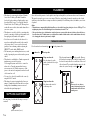 4
4
-
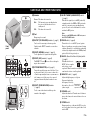 5
5
-
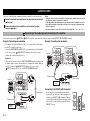 6
6
-
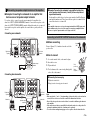 7
7
-
 8
8
-
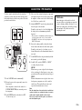 9
9
-
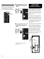 10
10
-
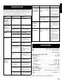 11
11
-
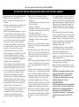 12
12
-
 13
13
-
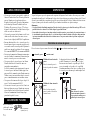 14
14
-
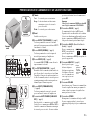 15
15
-
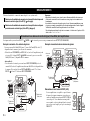 16
16
-
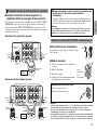 17
17
-
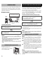 18
18
-
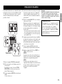 19
19
-
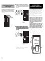 20
20
-
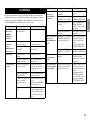 21
21
-
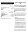 22
22
-
 23
23
-
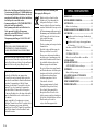 24
24
-
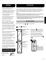 25
25
-
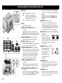 26
26
-
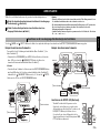 27
27
-
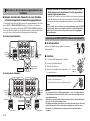 28
28
-
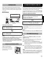 29
29
-
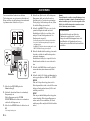 30
30
-
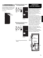 31
31
-
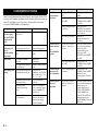 32
32
-
 33
33
-
 34
34
-
 35
35
-
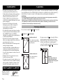 36
36
-
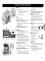 37
37
-
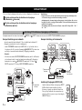 38
38
-
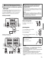 39
39
-
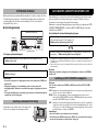 40
40
-
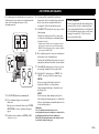 41
41
-
 42
42
-
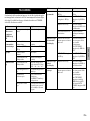 43
43
-
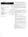 44
44
-
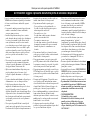 45
45
-
 46
46
-
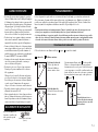 47
47
-
 48
48
-
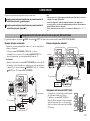 49
49
-
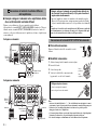 50
50
-
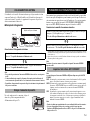 51
51
-
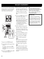 52
52
-
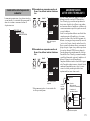 53
53
-
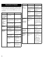 54
54
-
 55
55
-
 56
56
-
 57
57
-
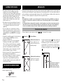 58
58
-
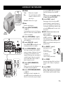 59
59
-
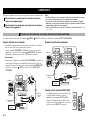 60
60
-
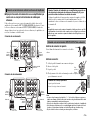 61
61
-
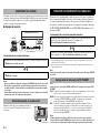 62
62
-
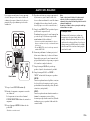 63
63
-
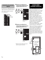 64
64
-
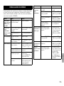 65
65
-
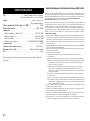 66
66
-
 67
67
-
 68
68
-
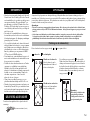 69
69
-
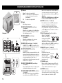 70
70
-
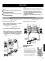 71
71
-
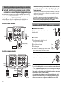 72
72
-
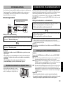 73
73
-
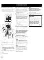 74
74
-
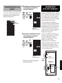 75
75
-
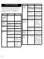 76
76
-
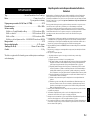 77
77
-
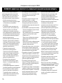 78
78
-
 79
79
-
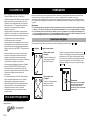 80
80
-
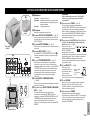 81
81
-
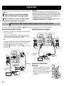 82
82
-
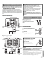 83
83
-
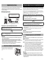 84
84
-
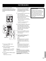 85
85
-
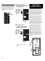 86
86
-
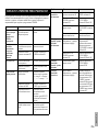 87
87
-
 88
88


Yamaha NS-SW500 El kitabı
- Kategori
- Hoparlörler
- Tip
- El kitabı
- Bu kılavuz aynı zamanda aşağıdakiler için de uygundur:
diğer dillerde
- español: Yamaha NS-SW500 El manual del propietario
- français: Yamaha NS-SW500 Le manuel du propriétaire
- italiano: Yamaha NS-SW500 Manuale del proprietario
- svenska: Yamaha NS-SW500 Bruksanvisning
- Deutsch: Yamaha NS-SW500 Bedienungsanleitung
- English: Yamaha NS-SW500 Owner's manual
- dansk: Yamaha NS-SW500 Brugervejledning
- русский: Yamaha NS-SW500 Инструкция по применению
- suomi: Yamaha NS-SW500 Omistajan opas
- Nederlands: Yamaha NS-SW500 de handleiding
- română: Yamaha NS-SW500 Manualul proprietarului