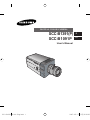
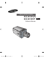
Samsung SCC-B1091P Kullanım kılavuzu
- Kategori
- Güvenlik kameraları
- Tip
- Kullanım kılavuzu
Bu kılavuz aynı zamanda aşağıdakiler için de uygundur:

User’s Manual
DIGITAL COLOR CAMERA
E
Tu
SCC-B1391(P)
SCC-B1091P
SCC-B1391,B1091-Eng.indd 1SCC-B1391,B1091-Eng.indd 1 2007-05-17 오전 9:35:362007-05-17 오전 9:35:36

E
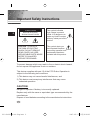
Important Safety Instructions
CAUTION: TO REDUCE
THE RISK OF ELECTRIC
SHOCK, DO NOT REMOVE
REAR COVER. NO USER
SERVICEABLE PARTS INSIDE.
REFER TO QUALIFIED
SERVICE PERSONNEL.
To prevent damage which may result in fire or electric shock hazard,
do not expose this appliance to rain or moisture.
This device complies with part 15 of the FCC Rules. Operation is
subject to the following two conditions.
1) This device may not cause harmful interference, and
2) This device must accept any interference that may cause
undesired operation.
CAUTION:
Danger of explosion if battery is incorrectly replaced.
Replace only with the same or equivalent type recommended by the
manufacturer.
Dispose of used batteries according to the manufacturer's instructions.
This symbol indicates
high voltage is present
inside. It is dangerous to
make any kind of contact
with any inside part of this
product.
This symbol alerts you
that important literature
concerning operation and
maintenance has been
included with this product.
CAUTION
RISK OF ELECTRIC
SHOCK DO NOT OPEN
2
SCC-B1391,B1091-Eng.indd 2SCC-B1391,B1091-Eng.indd 2 2007-05-17 오전 9:35:392007-05-17 오전 9:35:39

3
E
1. Read these instructions.
2. Keep these instructions.
3. Heed all warnings.
4. Follow all instructions.
5. Do not use this apparatus near water.
6. Clean only with dry cloth.
7. Do not block any ventilation openings. Install in accordance
with the manufacturer's instructions.
8. Do not install near any heat sources such as radiators, heat
registers, or other apparatus (including amplifiers) that produce
heat.
9. Do not defeat the safety purpose of the polarized or grounding-
type plug. A polarized plug has two blades with one wider than
the other. A grounding type plug has two blades and a third
grounding prong. The wide blade or the third prong are provided
for your safety. If the provided plug does not fit into your outlet,
consult an electrician for replacement of the obsolete outlet.
10. Protect the power cord from being from being walked on or
pinched particularly at plugs, convenience receptacles, and the
point where they exit from the apparatus.
11. Only use attachments/accessories specified by the manufacturer.
12. Use only with cart, stand, tripod, bracket, or table specified by the
manufacturer, or sold with the apparatus. When a used, caution
when moving the cart/apparatus combination to avoid injury from
tip-over.
13. Unplug this apparatus. When a cart is used, use caution when
moving the cart/apparatus combination to avoid injury from tip-
over.
14. Refer all servicing to qualified service personnel. Servicing is
required when the apparatus has been damaged in any way, such
as power-supply cord or plug is damaged, liquid has been spilled
or objects have fallen into the apparatus, the apparatus has been
exposed to rain or moisture, does not operate normally, or been
dropped.
SCC-B1391,B1091-Eng.indd 3SCC-B1391,B1091-Eng.indd 3 2007-05-17 오전 9:35:402007-05-17 오전 9:35:40

4
E
Chapter 1
Introduction
........................................................ 5
Chapter 2
Special Features
............................................... 6
Chapter 3
Installation
......................................................... 7
Checking the contents of the package
............ 7
Precautions in Installation and Use
................. 8
Connecting Auto Iris Lens Connector
............. 9
Lens Fixing
.................................................................
10
Setting Lens Selection Switch
...............................
11
Back Focus Adjustment
.................................... 11
Connecting Cables and Checking Operation
... 13
Chapter 4
Part Names and Functions
.............................. 15
Product Specification
........................................ 20
Contents
SCC-B1391,B1091-Eng.indd 4SCC-B1391,B1091-Eng.indd 4 2007-05-17 오전 9:35:412007-05-17 오전 9:35:41

5
E
This camera is the high-resolution monitoring camera of 540 TV Lines and can
provide the best monitoring function by connecting with the CCTV System.
>
In the mechanical fluorescent light environment, if you attach MANUAL IRIS
LENS and turn the ELC switch among FUNCTION switches on, color may be
rolled.
In this case, supply AC power before you turn L/L switch among FUNCTION
switches on. (NTSC:60HZ , PAL:50HZ)
Chapter 1 Introduction
COLOR ROLLING is the problem that color on the
monitor screen changes non-periodically.
This happens when White Balance is not fixed,
because a mechanical fluorescent light flickers
when it’s cycle is the same to the cycle of the power
frequency.
SCC-B1391,B1091-Eng.indd 5SCC-B1391,B1091-Eng.indd 5 2007-05-17 오전 9:35:422007-05-17 오전 9:35:42

6
E
High Sensitivity
It has an up-to-date 1/3" Super-HAD IT CCD for an image of high sensitivity.
Resolution
It realizes high resolution resulting from full digital image processing
supported by a state-of-art digital signal technology.
Superior Back Light Adjustment Function
In case the object has a bright illumination or sunlight behind it, this camera
adjusts the image shaded by the back light for clear photographs.
Digital Power Supply Synchronization Method
The Full Digital Method Line Lock is realized in this camera, which adjusts
the vertical camera synchronization directly to improve controllability and
reliability of the camera.
Chapter 2 Special Features
SCC-B1391,B1091-Eng.indd 6SCC-B1391,B1091-Eng.indd 6 2007-05-17 오전 9:35:432007-05-17 오전 9:35:43

7
E
This chapter describes what should be checked before installation, how to
set the installation environment, and what should be done during installation.
Then, it describes how to install the camera and connect the cable in actual
circumstances.
Chapter 3 Installation
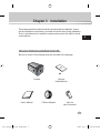
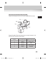
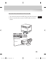
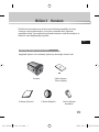
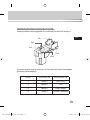
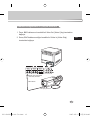
Be sure to check if the following items are included in the package.
Checking the contents of the package
Camera
Holder(Mount)
C Mount Adapter Auto Iris
Lens Connector
User's Manual
Camera
SCC-B1391,B1091-Eng.indd 7SCC-B1391,B1091-Eng.indd 7 2007-05-17 오전 9:35:442007-05-17 오전 9:35:44

E
Do not attempt to disassemble the camera yourself.
Be cautious in handling the camera. Avoid striking or shaking the camera.
Be cautious to avoid damage on the camera caused by improper storage
or operation.
Do not expose this camera to rain or moisture. Do not operate this
camera on a wet place.
Do not use strong or abrasive detergents when cleaning the camera
body. Use a dry cloth to clean the camera.
Keep the camera at a cool place away from the direct sunlight. Leaving it
under the direct sunlight may result in the malfunction of the unit.
Precautions in Installation and Use
SCC-B1391,B1091-Eng.indd 8SCC-B1391,B1091-Eng.indd 8 2007-05-17 오전 9:35:452007-05-17 오전 9:35:45

9
E
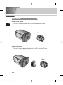
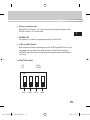
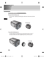
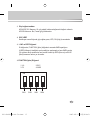
Connecting Auto Iris Lens Connector
Prepare the following Auto Iris Lens Connector supplied with the camera.
Connect the cable of the control cable, whose covering is stripped, to the
Auto Iris Lens Connector as shown below.
Rb
Pin3
Pin2
Pin4
Pin1
Pin No. DC Control Type
VIDEO Control Type
1 Damp(-) Power (+12V)
2 Damp(+) N/A
3 Damp(+) VIDEO Signal
4 Damp(-) GROUND
SCC-B1391,B1091-Eng.indd 9SCC-B1391,B1091-Eng.indd 9 2007-05-17 오전 9:35:462007-05-17 오전 9:35:46

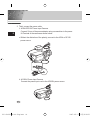
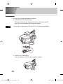
In case of CS lenses
Turn the CS lens clockwise until it is fixed as shown as follows.
In case of C lenses
Turn the C-mount adapter clockwise to fix it. Then turn the C lens
clockwise until it is fixed as follows.
Lens Fixing
CS lens
C lens
10
E
SCC-B1391,B1091-Eng.indd 10SCC-B1391,B1091-Eng.indd 10 2007-05-17 오전 9:35:472007-05-17 오전 9:35:47

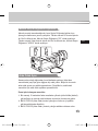
Back Focus Adjustment
Setting Lens Selection Switch
11
E
The camera back focus is adjusted at the plant before delivery, but some
lenses are out of focus though the number differs in types. If it's the case,
you should make the back focus adjustment as follows. First, this is the back
focus adjustment procedure for fixed focus lenses.
Lenses without zoom function
Image an object with high resolution(letticed) at more than 10m distance
and put the lens focus ring in the infinite(
∞
) position.
Rotate the BACK FOCUS control bar until the object is seen best.
Tighten the BACK FOCUS control bar fixing screw.
When lens mounting is completed, set the Lens selection Switch on the side
of the camera according to the mounted lens type. When the mounted lens
is an Auto Iris Lens of the DC control type, set the Lens Selection Switch to
"DC". When the mounted lens is an Auto Iris Lens of the Video control type,
set the Lens Selection Switch to "VIDEO".
SCC-B1391,B1091-Eng.indd 11SCC-B1391,B1091-Eng.indd 11 2007-05-17 오전 9:35:492007-05-17 오전 9:35:49

12
E
Lenses with zoom function
Image an object with high resolution(letticed) at a distance of 3 to 5 m
and zoom in the lens as close to TELE as possible. Then adjust the lens
focus bar until the object is seen best.
Zoom in the lens as close to WIDE as possible and adjust the BACK
FOCUS adjustment bar until the object is seen best.
Repeat from to above 2 or 3 times until the focus on the ZOOM
TELE side is in line with that on the ZOOM WIDE side.
BACK FOCUS
CONTROL BAR
SCC-B1391,B1091-Eng.indd 12SCC-B1391,B1091-Eng.indd 12 2007-05-17 오전 9:35:502007-05-17 오전 9:35:50

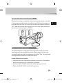
Connecting Cables and Checking Operation
13
E
1 First, connect the connector of the BNC cable to the Video Out terminal
2 Second, connect the other connector of the BNC cable to the Video In
terminal.
BNC cable
Video Out Terminal
Video In Terminal of
Monitor Rear Surface
SCC-B1391,B1091-Eng.indd 13SCC-B1391,B1091-Eng.indd 13 2007-05-17 오전 9:35:512007-05-17 오전 9:35:51

14
E
3 Third, connect the power cable.
AC24V/DC12V Power Input Camera.
Connect 2 lines of the power adapter using a screwdriver to the power
IN Terminal of the camera as shown below.
>
Without the distinction of the polarity, connect to the AC24 or DC12V
power source.
AC230V Power Input Camera
Connect the power input cord to the AC230V power source.
SCC-B1391,B1091-Eng.indd 14SCC-B1391,B1091-Eng.indd 14 2007-05-17 오전 9:35:522007-05-17 오전 9:35:52

15
E
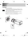
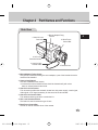
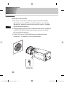
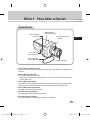
Chapter 4 Part Names and Functions
Side View
Mount Adapter Fixing Groove
This groove is used for screwing the mount adapter, a part of the bracket where the
camera will be installed.
Camera Lens(Option)
This lens is installed in the camera.
>
A camera lens with a stained surface should be cleaned softly with a lens
tissue or ethanol painted cotton cloth.
Auto Iris Lens Connector
This connector provides the automatic shutter lens with power supply, control signal,
video signal, or DC signal necessary for the control of the lens shutter.
Auto Iris Lens Control Cable
This cable transmits signal which controls the Iris.
ALC Lens Selection Switch
This Switch is used for select the type of Lens.
Back Focus Control Bar
This bar is used for set back focus of the camera.
Auto Iris Lens
Control Cable
ALC Lens
Selection Switch
Auto Iris Lens
Connector
Mount Adapter Fixing
Groove
Back Focus
Control Bar
Camera Lens
SCC-B1391,B1091-Eng.indd 15SCC-B1391,B1091-Eng.indd 15 2007-05-17 오전 9:35:532007-05-17 오전 9:35:53

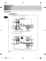
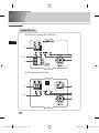
Rear View
16
E
AC24V/DC12V Camera (SCC-B1391(P))
AC230V Camera (SCC-1091P)
SCC-B1391,B1091-Eng.indd 16SCC-B1391,B1091-Eng.indd 16 2007-05-17 오전 9:35:542007-05-17 오전 9:35:54

17
E
Power connection port
AC24V/DC12V Camera : It is a port connected to the power adaptor cable.
AC230V Camera : It is Power cord.
POWER LED
If the power of a camera is supplied normally, the LED is ON.
INC and DEC Switch
Both switches increase or decrease the profit of RED and BLUE to fix a color
temperature as you wish while AWB among the FUNCTION switches is
off(USER) and control the vertical synchronous phase while both AWB and
L/L are on.
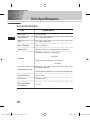
FUNCTION Switch
1. L/L 2. ELC
3. FL 4. AWB
SW1 SW2 SW3 SW4
ON
SCC-B1391,B1091-Eng.indd 17SCC-B1391,B1091-Eng.indd 17 2007-05-17 오전 9:35:552007-05-17 오전 9:35:55

18
E
1) SW1(L/L) :
Set to OFF, the camera activates the internal synchronization mode and set to ON, the power
synchronization mode. If you connect multi cameras to the sequential switcher to enter the
automatic conversion mode, the screen will bounce every screen while the camera stays
in INT(internal synchronization). Such bouncing phenomena may be cleared and screen
conversion becomes smooth by setting the L/L switch to ON and using the INT/DEC switch to
control the vertical synchronous phase.
>
If you want to control the vertical synchronous phase with the INT/DEC switch when L/L is set
to ON, you shall set SW4 to AWB ON.
>
In case of DC12V, INT(internal synchronizer) will be fixed without regard to ON/OFF of L/L.
2) SW2(ELC) :
Use this switch with the Manual Iris Lens. While this switch is ON, the speed of the electronic
shutter varies with the brightness of the subject from 1/60(50) to 1/100,000 sec for automatically
controlling the brightness of the screen. However, with the Auto Iris Lens (DC or Video Control),
be sure to switch OFF.
Color Rolling may occur in this mode. In that case, input AC power source to the camera and
select SW1 "ON".
(NTSC : 60HZ, PAL : 50HZ)
3) SW3(FL):
This is to prevent flicker on the screen when NTSC system is used in 50HZ power supply region and
PAL system is used in 60HZ power supply region. That is to prevent shaking on the screen resulted
from the discordance of the vertical sync frequency and the flicker frequency of the illumination. While
this switch is ON, the electronic shutter is fixed to 1/100sec (NTSC) or 1/120 sec (PAL).
4) SW4(AWB):
When setting up ON, the color of screen is adjusted automatically in accordance with the change
of lighting color temperature by the change of outer environment. (ATW) If the lighting condition
is steady, OFF setting is available. The camera memorizes the lighting color temperature at the
time when the switch setting is changed from ON to OFF, and the camera color is adjusted to the
memorized color temperature. (AWC) If the lighting color temperature is changed and you want
to make the camera be memorized/operated with the changed color temperature, re-operate the
switch On/Off operation. However, be aware that an error may occur under the following conditions
.
First, a case that the subject is big, single color of the high chroma, and in the center of the
screen or a case with almost no white color on the screen.
Second, a case with a specific illumination such as a natrium lamp
SCC-B1391,B1091-Eng.indd 18SCC-B1391,B1091-Eng.indd 18 2007-05-17 오전 9:35:562007-05-17 오전 9:35:56

19
E
DC IRIS Level Controller
When the ALC lens selection switch is set to DC, use the same control bar as the
driver to control the IRIS level.
Video Output Port
This port shall be connected to the monitor video input port or equivalent. You
may output camera video signals through this port.
SCC-B1391,B1091-Eng.indd 19SCC-B1391,B1091-Eng.indd 19 2007-05-17 오전 9:35:572007-05-17 오전 9:35:57

20
E
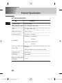
Product Specification
SCC-B1391P/B1091P
ITEM
Contents
Product Type
CCTV Camera
Broadcasting System
PAL STANDARD SYSTEM
CCD
1/3" Super-HAD CCD
Effective Pixels
752(H) x 582(V)
Scanning Type
625 Line, 2:1 Interlace
INTERNAL : 15,625Hz(H)
50 Hz(V)
LINE LOCK : 15,625Hz(H)
50 Hz(V)
INTERNAL
LINE LOCK(When AC Power source is used)
Resolution(H)
540 TV Lines
S/N Ratio
About 50dB
Frequency
Sync Type
Minimum Illumination
of Object
0.3 Lux
SCC-B1391,B1091-Eng.indd 20SCC-B1391,B1091-Eng.indd 20 2007-05-17 오전 9:35:582007-05-17 오전 9:35:58
Sayfa yükleniyor...
Sayfa yükleniyor...
Sayfa yükleniyor...
Sayfa yükleniyor...
Sayfa yükleniyor...
Sayfa yükleniyor...
Sayfa yükleniyor...
Sayfa yükleniyor...
Sayfa yükleniyor...
Sayfa yükleniyor...
Sayfa yükleniyor...
Sayfa yükleniyor...
Sayfa yükleniyor...
Sayfa yükleniyor...
Sayfa yükleniyor...
Sayfa yükleniyor...
Sayfa yükleniyor...
Sayfa yükleniyor...
Sayfa yükleniyor...
Sayfa yükleniyor...
Sayfa yükleniyor...
Sayfa yükleniyor...
Sayfa yükleniyor...
Sayfa yükleniyor...
Sayfa yükleniyor...
Sayfa yükleniyor...
Sayfa yükleniyor...
Sayfa yükleniyor...
-
 1
1
-
 2
2
-
 3
3
-
 4
4
-
 5
5
-
 6
6
-
 7
7
-
 8
8
-
 9
9
-
 10
10
-
 11
11
-
 12
12
-
 13
13
-
 14
14
-
 15
15
-
 16
16
-
 17
17
-
 18
18
-
 19
19
-
 20
20
-
 21
21
-
 22
22
-
 23
23
-
 24
24
-
 25
25
-
 26
26
-
 27
27
-
 28
28
-
 29
29
-
 30
30
-
 31
31
-
 32
32
-
 33
33
-
 34
34
-
 35
35
-
 36
36
-
 37
37
-
 38
38
-
 39
39
-
 40
40
-
 41
41
-
 42
42
-
 43
43
-
 44
44
-
 45
45
-
 46
46
-
 47
47
-
 48
48


Samsung SCC-B1091P Kullanım kılavuzu
- Kategori
- Güvenlik kameraları
- Tip
- Kullanım kılavuzu
- Bu kılavuz aynı zamanda aşağıdakiler için de uygundur:
diğer dillerde
- English: Samsung SCC-B1091P User manual
İlgili makaleler
-
Samsung SCC-B2091P Kullanım kılavuzu
-
-
-
-
-
-
-
-
-