
EN
Owner’s Manual
Keep This Manual For Future Reference.

Owner’s Manual
2
Contents
PRECAUTIONS................................... 5
Introduction .................................... 7
Welcome! ..........................................................7
Accessories.........................................................7
About utility software.........................................7
About firmware updates.....................................7
About the Owner’s Manual ................................7
Conventions in this manual................................7
An overview of the CL series ........... 8
Features .............................................................8
About the models ..............................................9
Controls and functions .................. 10
Top panel ........................................................10
Front Panel ......................................................16
Rear Panel........................................................16
Touch screen.................................. 18
Basic touch screen operations ..........................18
The on-screen user interface ............................18
Viewing the touch screen.................................20
Entering names................................................21
Using the tool buttons .....................................22
Using libraries ..................................................23
Initializing settings ...........................................26
Copying/pasting settings .................................26
Comparing two settings...................................27
Basic operation of the CL series .... 28
Controlling selected channels
(SELECTED CHANNEL section) ..................28
Controlling eight channels as a group
(Centralogic section).................................28
Using the top panel
(Channel Strip section)..............................29
Connections ................................... 31
About network connections .............................31
Connecting to I/O devices ...............................31
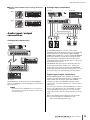
Audio input/output connections ......................33
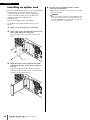
Installing an option card ..................................34
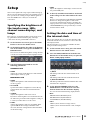
Setup.............................................. 35
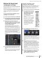
Specifying the brightness of the touch screen,
LEDs, channel name displays, and lamps...35
Setting the date and time of the internal
clock .........................................................35
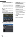
Word clock connections and settings ...............36
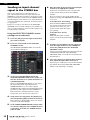
Making HA (Head Amp) analog gain settings...37
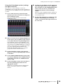
Sending an input channel signal to the
STEREO bus...............................................38
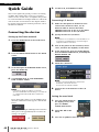
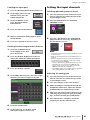
Quick Guide ................................... 40
Connecting the devices....................................40
Setting the input channels ...............................41
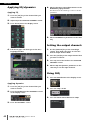
Applying EQ/dynamics.....................................42
Setting the output channels .............................42
Using GEQ .......................................................42
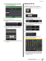
Applying effects ...............................................43
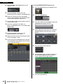
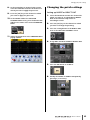
Changing the patch settings ............................45
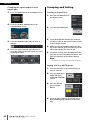
Grouping and linking.......................................46
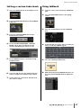
Setting a custom fader bank ............................47
Using talkback..................................................47
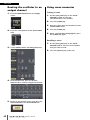
Routing the oscillator to an output channel......48
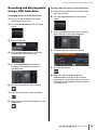
Using scene memories .....................................48
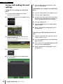
Recording and playing audio using a USB
flash drive .................................................49
Saving and loading the unit settings ................50
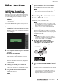
Other functions ............................. 51
Initializing the unit to factory default settings...51
Restoring the current scene to the default
state..........................................................51
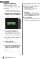
Adjusting the faders (Calibration function) .......52
Troubleshooting ............................ 53
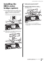
Installing the MBCL meter bridge
(option) ......................................... 55
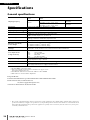
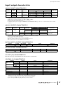
Specifications................................. 56
General specifications ......................................56
Input/output characteristics .............................57
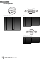
Pin Assignment ................................................58
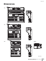
Dimensions .................................... 59
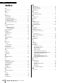
Index .............................................. 60
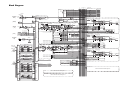
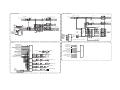
Block Diagram ............ End of Manual
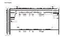
Level Diagram............. End of Manual

Owner’s Manual
3
The above warning is located on the rear of the unit.
L’avertissement ci-dessus est situé sur l’arrière de l’unité.
Explanation of Graphical Symbols
Explication des symboles
The lightning flash with arrowhead symbol within an equilateral triangle is intended to alert the user to the presence of uninsulated “danger-
ous voltage” within the product’s enclosure that may be of sufficient magnitude to constitute a risk of electric shock to persons.
L’éclair avec une flèche à l’intérieur d’un triangle équilatéral est destiné à attirer l’attention de l’utilisateur sur la présence d’une « tension
dangereuse » non isolée à l’intérieur de l’appareil, pouvant être suffisamment élevée pour constituer un risque d’électrocution.
The exclamation point within an equilateral triangle is intended to alert the user to the presence of important operating and maintenance (ser-
vicing) instructions in the literature accompanying the product.
Le point d’exclamation à l’intérieur d’un triangle équilatéral est destiné à attirer l’attention de l’utilisateur sur la présence d’instructions
importantes sur l’emploi ou la maintenance (réparation) de l’appareil dans la documentation fournie.
IMPORTANT SAFETY
INSTRUCTIONS
1 Read these instructions.
2 Keep these instructions.
3 Heed all warnings.
4 Follow all instructions.
5 Do not use this apparatus near water.
6 Clean only with dry cloth.
7 Do not block any ventilation openings. Install in accordance with the
manufacturer’s instructions.
8 Do not install near any heat sources such as radiators, heat registers,
stoves, or other apparatus (including amplifiers) that produce heat.
9 Do not defeat the safety purpose of the polarized or grounding-type
plug. A polarized plug has two blades with one wider than the other. A
grounding type plug has two blades and a third grounding prong. The
wide blade or the third prong are provided for your safety. If the pro-
vided plug does not fit into your outlet, consult an electrician for
replacement of the obsolete outlet.
10 Protect the power cord from being walked on or pinched particularly
at plugs, convenience receptacles, and the point where they exit from
the apparatus.
11 Only use attachments/accessories specified by the manufacturer.
12 Use only with the cart, stand, tripod, bracket, or
table specified by the manufacturer, or sold with
the apparatus. When a cart is used, use caution
when moving the cart/apparatus combination to
avoid injury from tip-over.
13 Unplug this apparatus during lightning storms
or when unused for long periods of time.
14 Refer all servicing to qualified service personnel. Servicing is
required when the apparatus has been damaged in any way, such as
power-supply cord or plug is damaged, liquid has been spilled or
objects have fallen into the apparatus, the apparatus has been
exposed to rain or moisture, does not operate normally, or has been
dropped.
(UL60065_03)
PRÉCAUTIONS CONCER-
NANT LA SÉCURITÉ
1 Lire ces instructions.
2 Conserver ces instructions.
3 Tenir compte de tous les avertissements.
4 Suivre toutes les instructions.
5 Ne pas utiliser ce produit à proximité d’eau.
6 Nettoyer uniquement avec un chiffon propre et sec.
7 Ne pas bloquer les orifices de ventilation. Installer l’appareil confor-
mément aux instructions du fabricant.
8 Ne pas installer l’appareil à proximité d’une source de chaleur comme
un radiateur, une bouche de chaleur, un poêle ou tout autre appareil
(y compris un amplificateur) produisant de la chaleur.
9 Ne pas modifier le système de sécurité de la fiche polarisée ou de la
fiche de terre. Une fiche polarisée dispose de deux broches dont une
est plus large que l’autre. Une fiche de terre dispose de deux broches
et d’une troisième pour le raccordement à la terre. Cette broche plus
large ou cette troisième broche est destinée à assurer la sécurité de
l’utilisateur. Si la fiche équipant l’appareil n’est pas compatible avec
les prises de courant disponibles, faire remplacer les prises par un
électricien.
10 Acheminer les cordons d’alimentation de sorte qu’ils ne soient pas
piétinés ni coincés, en faisant tout spécialement attention aux fiches,
prises de courant et au point de sortie de l’appareil.
11 Utiliser exclusivement les fixations et accessoires spécifiés par le
fabricant.
12 Utiliser exclusivement le chariot, le stand, le tré-
pied, le support ou la table recommandés par le
fabricant ou vendus avec cet appareil. Si l’appa-
reil est posé sur un chariot, déplacer le chariot
avec précaution pour éviter tout risque de chute
et de blessure.
13 Débrancher l’appareil en cas d’orage ou
lorsqu’il doit rester hors service pendant une période prolongée.
14 Confier toute réparation à un personnel qualifié. Faire réparer l’appa-
reil s’il a subi tout dommage, par exemple si la fiche ou le cordon
d’alimentation est endommagé, si du liquide a coulé ou des objets
sont tombés à l’intérieur de l’appareil, si l’appareil a été exposé à la
pluie ou à de l’humidité, si l’appareil ne fonctionne pas normalement
ou est tombé.
(UL60065_03)
WARNING
TO REDUCE THE RISK OF FIRE OR ELECTRIC SHOCK, DO NOT
EXPOSE THIS APPARATUS TO RAIN OR MOISTURE.
AVERTISSEMENT
POUR RÉDUIRE LES RISQUES D’INCENDIE OU DE DÉCHARGE
ÉLECTRIQUE, N’EXPOSEZ PAS CET APPAREIL À LA PLUIE OU À
L’HUMIDITÉ.

Owner’s Manual
4
1. IMPORTANT NOTICE: DO NOT MODIFY THIS UNIT!
This product, when installed as indicated in the instructions con-
tained in this manual, meets FCC requirements. Modifications not
expressly approved by Yamaha may void your authority, granted by
the FCC, to use the product.
2. IMPORTANT: When connecting this product to accessories and/
or another product use only high quality shielded cables. Cable/s
supplied with this product MUST be used. Follow all installation
instructions. Failure to follow instructions could void your FCC
authorization to use this product in the USA.
3. NOTE: This product has been tested and found to comply with the
requirements listed in FCC Regulations, Part 15 for Class “B” digital
devices. Compliance with these requirements provides a reason-
able level of assurance that your use of this product in a residential
environment will not result in harmful interference with other elec-
tronic devices. This equipment generates/uses radio frequencies
and, if not installed and used according to the instructions found in
the users manual, may cause interference harmful to the operation
of other electronic devices. Compliance with FCC regulations does
* This applies only to products distributed by YAMAHA CORPORATION OF AMERICA. (class B)
not guarantee that interference will not occur in all installations. If
this product is found to be the source of interference, which can be
determined by turning the unit “OFF” and “ON”, please try to elimi-
nate the problem by using one of the following measures:
Relocate either this product or the device that is being affected by
the interference.
Utilize power outlets that are on different branch (circuit breaker or
fuse) circuits or install AC line filter/s.
In the case of radio or TV interference, relocate/reorient the
antenna. If the antenna lead-in is 300 ohm ribbon lead, change the
lead-in to co-axial type cable.
If these corrective measures do not produce satisfactory results,
please contact the local retailer authorized to distribute this type of
product. If you can not locate the appropriate retailer, please con-
tact Yamaha Corporation of America, Electronic Service Division,
6600 Orangethorpe Ave, Buena Park, CA90620
The above statements apply ONLY to those products distributed by
Yamaha Corporation of America or its subsidiaries.
FCC INFORMATION (U.S.A.)
IMPORTANT NOTICE FOR THE UNITED KINGDOM
Connecting the Plug and Cord
WARNING: THIS APPARATUS MUST BE EARTHED
IMPORTANT. The wires in this mains lead are coloured in accordance
with the following code:
GREEN-AND-YELLOW : EARTH
BLUE : NEUTRAL
BROWN : LIVE
As the colours of the wires in the mains lead of this apparatus may not
correspond with the coloured markings identifying the terminals in
your plug proceed as follows:
The wire which is coloured GREEN-and-YELLOW must be connected
to the terminal in the plug which is marked by the letter E or by the
safety earth symbol or colored GREEN or GREEN-and-YELLOW.
The wire which is coloured BLUE must be connected to the terminal
which is marked with the letter N or coloured BLACK.
The wire which is coloured BROWN must be connected to the termi-
nal which is marked with the letter L or coloured RED.
(3 wires)
ADVARSEL!
Lithiumbatteri—Eksplosionsfare ved fejlagtig håndtering. Udskiftning
må kun ske med batteri af samme fabrikat og type. Levér det brugte
batteri tilbage til leverandoren.
VARNING
Explosionsfara vid felaktigt batteribyte. Använd samma batterityp eller
en ekvivalent typ som rekommenderas av apparattillverkaren.
Kassera använt batteri enligt fabrikantens instruktion.
VAROITUS
Paristo voi räjähtää, jos se on virheellisesti asennettu. Vaihda paristo
ainoastaan laitevalmistajan suosittelemaan tyyppiin. Hävitä käytetty
paristo valmistajan ohjeiden mukaisesti.
(lithium caution)
NEDERLAND / THE NETHERLANDS
• Dit apparaat bevat een lithium batterij voor geheugen back-up.
• This apparatus contains a lithium battery for memory back-up.
• Raadpleeg uw leverancier over de verwijdering van de batterij op het
moment dat u het apparaat ann het einde van de levensduur of
gelieve dan contact op te nemen met de vertegenwoordiging van
Yamaha in uw land.
• For the removal of the battery at the moment of the disposal at the
end of life please consult your retailer or Yamaha representative
office in your country.
• Gooi de batterij niet weg, maar lever hem in als KCA.
• Do not throw away the battery. Instead, hand it in as small chemical
waste.
(lithium disposal)
This product contains a battery that contains perchlorate material.
Perchlorate Material—special handling may apply,
See www.dtsc.ca.gov/hazardouswaste/perchlorate.
* This applies only to products distributed by
YAMAHA CORPORATION OF AMERICA.
(Perchlorate)
* This applies only to products distributed by
YAMAHA CORPORATION OF AMERICA.
COMPLIANCE INFORMATION STATEMENT
(DECLARATION OF CONFORMITY PROCEDURE)
Responsible Party : Yamaha Corporation of America
Address : 6600 Orangethorpe Ave., Buena Park, Calif.
90620
Telephone : 714-522-9011
Type of Equipment : Digital Mixing Console
Model Name : CL5/CL3/CL1
This device complies with Part 15 of the FCC Rules.
Operation is subject to the following two conditions:
1) this device may not cause harmful interference, and
2) this device must accept any interference received including interfer-
ence that may cause undesired operation.
See user manual instructions if interference to radio reception is sus-
pected.
(FCC DoC)
This product contains a high intensity lamp that contains
a small amount of mercury. Disposal of this material
may be regulated due to environmental considerations.
For disposal information in the United States, refer to
the Electronic Industries Alliance web site:
www.eiae.org
(mercury)* This applies only to products distributed by
YAMAHA CORPORATION OF AMERICA.
(class b korea)

Owner’s Manual
5
PRECAUTIONS
PLEASE READ CAREFULLY BEFORE PROCEEDING
* Please keep this manual in a safe place for future reference.
WARNING
Always follow the basic precautions listed below to avoid
the possibility of serious injury or even death from
electrical shock, short-circuiting, damages, fire or other
hazards. These precautions include, but are not limited
to, the following:
• Do not place the power cord near heat sources such as heaters or radiators, and
do not excessively bend or otherwise damage the cord, place heavy objects on
it, or place it in a position where anyone could walk on, trip over, or roll anything
over it.
• Only use the voltage specified as correct for the device. The required voltage is
printed on the name plate of the device.
• Use only the supplied power cord/plug.
If you intend to use the device in an area other than in the one you purchased,
the included power cord may not be compatible. Please check with your Yamaha
dealer.
• Check the electric plug periodically and remove any dirt or dust which may have
accumulated on it.
• Be sure to connect to an appropriate outlet with a protective grounding
connection. Improper grounding can result in electrical shock.
• This device contains no user-serviceable parts. Do not open the device or
attempt to disassemble the internal parts or modify them in any way. If it should
appear to be malfunctioning, discontinue use immediately and have it inspected
by qualified Yamaha service personnel.
• Do not expose the device to rain, use it near water or in damp or wet conditions,
or place on it any containers (such as vases, bottles or glasses) containing
liquids which might spill into any openings. If any liquid such as water seeps
into the device, turn off the power immediately and unplug the power cord from
the AC outlet. Then have the device inspected by qualified Yamaha service
personnel.
• Never insert or remove an electric plug with wet hands.
• Do not put burning items, such as candles, on the unit. A burning item may fall
over and cause a fire.
• When one of the following problems occur, immediately turn off the power
switch and disconnect the electric plug from the outlet. Then have the device
inspected by Yamaha service personnel.
- The power cord or plug becomes frayed or damaged.
- It emits unusual smells or smoke.
- Some object has been dropped into the instrument.
- There is a sudden loss of sound during use of the device.
CAUTION
Always follow the basic precautions listed below to avoid
the possibility of physical injury to you or others, or
damage to the device or other property. These
precautions include, but are not limited to, the following:
• When removing the electric plug from the device or an outlet, always hold the
plug itself and not the cord. Pulling by the cord can damage it.
• Remove the electric plug from the outlet when the device is not to be used for
extended periods of time, or during electrical storms.
• Do not place the device in an unstable position where it might accidentally fall
over.
• Do not block the vents. This device has ventilation holes at the rear to prevent
the internal temperature from becoming too high. In particular, do not place the
device on its side or upside down. Inadequate ventilation can result in
overheating, possibly causing damage to the device(s), or even fire.
• Do not place the device in a location where it may come into contact with
corrosive gases or salt air. Doing so may result in malfunction.
• Before moving the device, remove all connected cables.
• When setting up the device, make sure that the AC outlet you are using is easily
accessible. If some trouble or malfunction occurs, immediately turn off the
power switch and disconnect the plug from the outlet. Even when the power
switch is turned off, electricity is still flowing to the product at the minimum
level. When you are not using the product for a long time, make sure to unplug
the power cord from the wall AC outlet.
• When transporting or moving the device, always use two or more people.
Attempting to lift the device by yourself may damage your back, result in other
injury, or cause damage to the device itself.
• Before connecting the device to other devices, turn off the power for all devices.
Before turning the power on or off for all devices, set all volume levels to
minimum.
• Remove the power plug from the AC outlet when cleaning the device.
• Do not insert your fingers or hands in any gaps or openings on the device
(vents).
• Avoid inserting or dropping foreign objects (paper, plastic, metal, etc.) into any
gaps or openings on the device (vents). If this happens, turn off the power
immediately and unplug the power cord from the AC outlet. Then have the
device inspected by qualified Yamaha service personnel.
• Do not rest your weight on the device or place heavy objects on it, and avoid use
excessive force on the buttons, switches or connectors.
• Do not use headphones for a long period of time at a high or uncomfortable
volume level, since this can cause permanent hearing loss. If you experience
any hearing loss or ringing in the ears, consult a physician.
Power supply/Power cord
Do not open
Water warning
Fire warning
If you notice any abnormality
Power supply/Power cord
Location
Connections
Maintenance
Handling caution
PA_en_1 1/2

Owner’s Manual
6
• This device has a built-in backup battery that maintains internal clock data even
when the device’s power is switched off.
However, the backup battery will eventually become depleted, and when that
happens the internal clock data will be reset. Replace the backup battery before it
becomes fully depleted.
When the backup battery is running low, the LCD display indicates “Low
Battery” when you start up the system.
In this case, contact your Yamaha dealer and have qualified Yamaha service
personnel replace the backup battery.
The average life of the backup battery is approximately five years, depending on
operating conditions.
NOTICE
To avoid the possibility of malfunction/ damage to the
product, damage to data, or damage to other property,
follow the notices below.
• Do not use the instrument in the vicinity of a TV, radio, stereo equipment, mobile
phone, or other electric devices. Otherwise, the instrument, TV, or radio may
generate noise.
• Do not expose the instrument to excessive dust or vibrations, or extreme cold or
heat (such as in direct sunlight, near a heater, or in a car during the day) to
prevent the possibility of panel disfiguration, damage to the internal
components or unstable operation.
(Verified operating temperature range: 5° – 40°C, or 41° – 104°F.)
• Do not place vinyl, plastic or rubber objects on the instrument, since this might
discolor the panel or keyboard.
• Condensation may occur if the ambient temperature around the device fluctuates
drastically (for example, if the device is relocated or placed under a fast-acting
air cooling or heating system, etc.).
Using the device while condensation is present may result in malfunction. Do
not turn on the power to the device for several hours until condensation
disappears. Only then is it safe to start the device.
• To protect against data loss through media damage, we recommend that you
save your important data onto two USB storage devices/external media.
Information
About copyrights
* Copying of the commercially available musical data including but not limited to
MIDI data and/or audio data is strictly prohibited except for your personal use.
About functions/data bundled with the instrument
* MPEG Layer-3 audio coding technology licensed from Fraunhofer
IIS and Thomson.
* Supply of this product does not convey a license nor imply any right
to distribute content created with this product in revenue-generating broadcast
systems (terrestrial, satellite, cable and/or other distribution channels),
streaming applications (via Internet, intranets, and/or other networks), other
content distribution systems(pay-audio or audio-on-demand applications and
the like) or on physical media (compact discs, digital versatile discs,
amiconductor chips, hard drives, memory cards and the like). An independent
license for such use is required.
For ditails, please visit http://mp3licensing.com/
About this manual
* The illustrations and LCD screens as shown in this manual are for instructional
purposes only, and may appear somewhat different from those on your
instrument.
* Windows is a registered trademark of Microsoft(R) Corporation in the United
States and other countries.
* Apple, Mac, Macintosh and iPad are trademarks of Apple Inc., registered in the
U.S. and other countries.
* The company names and product names in this manual are the trademarks or
registered trademarks of their respective companies.
Always turn the power off when the device is not in use.
(weee_eu)
Backup battery
Handling and Maintenance
Saving data
Yamaha cannot be held responsible for damage caused by improper use or
modifications to the device, or data that is lost or destroyed.
Information for Users on Collection and Disposal of Old
Equipment
This symbol on the products, packaging, and/or
accompanying documents means that used electrical
and electronic products should not be mixed with
general household waste.
For proper treatment, recovery and recycling of old
products, please take them to applicable collection
points, in accordance with your national legislation and
the Directives 2002/96/EC.
By disposing of these products correctly, you will help to save valuable
resources and prevent any potential negative effects on human health and the
environment which could otherwise arise from inappropriate waste handling.
For more information about collection and recycling of old products, please
contact your local municipality, your waste disposal service or the point of sale
where you purchased the items.
[For business users in the European Union]
If you wish to discard electrical and electronic equipment, please contact your
dealer or supplier for further information.
[Information on Disposal in other Countries outside the European
Union]
This symbol is only valid in the European Union. If you wish to discard these
items, please contact your local authorities or dealer and ask for the correct
method of disposal.
PA_en_1 2/2

Introduction
Owner’s Manual
7
Introduction
Welcome!
Thank you for choosing a Yamaha CL series CL5/CL3/CL1
Digital Mixing Console. To take full advantage of the
superior features and performance offered by your
CL-series console, and to enjoy years of trouble-free use,
please read this owner’s manual carefully before operating
your console. After you have read the manual, keep it in a
safe place.
Accessories
• AC power cord
• Owner’s Manual (this book)
• Dante Virtual Soundcard Token leaflet
About utility software
CL-series products can be used with a variety of utility
software.
•CL Editor
This software application enables you to set up and operate
the unit from a connected computer. You can also use the
application to back up console settings or set console
parameters without connecting the unit.
• Console File Converter
This software application enables you to convert Yamaha
PM5D, M7CL, or LS9 settings files to or from CL-series
setting files.
• CL StageMix
This software application enables you to control the unit
remotely from an iPad on a WiFi network.
• MonitorMix
This app allows you to use your mobile device and a Wi-Fi
connection to adjust the CL-series console’s monitor mix
remotely.
Information about these software applications is available
on the Yamaha pro audio website:
http://www.yamahaproaudio.com/
Information about downloading, installing and setting up
the software applications is available on the website listed
above. In addition, refer to the installation guide that
comes with each downloaded application.
About firmware updates
This product enables you to update the unit firmware to
improve the operation, add functions, and correct possible
malfunctions. The following two types of firmware are
available for the unit.
• Console firmware
• Dante module firmware
You must update each type of firmware separately.
Details on updating the firmware are available on the
following website:
http://www.yamahaproaudio.com/
For information about updating and setting up the unit,
please refer to the firmware update guide available on the
website.
About the Owner’s Manual
Owner’s Manual (this book)
This book primarily explains panel controls and functions
and basic operation of the CL series.
Reference Manual (PDF format;
downloadable from the website)
This book primarily explains details about functions,
effects parameters, and MIDI.
Using the PDF manual
The Reference Manual is an electronic file in PDF format.
You can read this book on a computer. Use Adobe® Reader®
to read this book on screen, search for words very quickly,
print specific pages, or click links to display sections of
special interest. The ability to search for words, or to follow
links directly to relevant sections in the document, are
helpful attributes of this electronic file format. We
encourage you to take advantage of these benefits.
You can download the latest Adobe Reader application
from the website listed below.
http://www.adobe.com/
Help file (XML file; downloadable from
the website)
You can read this Help file on the unit’s screen. Install the
file on the unit, then press the Help button on the display to
view related sections.
You can download the Reference Manual and Help file
from the following website.
http://www.yamahaproaudio.com/
Conventions in this manual
In this manual, switch-type controls on the panel are called
“keys.” Control knobs on the panel are called “knobs.”
Some knobs rotate from a minimum value to a maximum
value, while others rotate endlessly.
Virtual buttons displayed on the screen are called “buttons,”
and virtual knobs are called “knobs.”
Controls located on the panel are enclosed in square
brackets [ ] (e.g., [CUE] key) to distinguish them from
virtual buttons and knobs displayed on screen. For certain
controls, the name of the section appears before the
brackets (e.g., SCENE MEMORY [STORE] key).

An overview of the CL series
Owner’s Manual
8
An overview of the
CL series
Features
CL series digital mixing consoles create high-quality,
refined, live-sound environments.
These consoles carry forward the digital evolution of a
broad array of advanced concepts, including Yamaha’s
exclusive “Centralogic
TM
” control interface, which helps to
make the consoles easy and intuitive to use.
The built-in effect processor and an I/O device can
accommodate the most demanding situations at the
highest level of quality, while retaining the flexibility
necessary to configure a system that meets your needs.
User interface friendly to newcomers but
familiar to seasoned users
All channels routed to the top-panel faders are organized
into a “Fader Bank” that enables you to select and switch a
group of channels easily. The Fader Bank holds input and
output channel banks, as well as custom fader banks. The
custom fader banks enable you to select various
combinations of channels, regardless of channel types.
Each channel strip offers easy visual identification. The
channel name appears on a display, and an indicator shows
the channel color. You can adjust the brightness of each
indicator across a broad range to accommodate dimly-lit
environments.
The SELECTED CHANNEL section located to the left of
the display lets you use the knobs to control the main
parameters (gain, EQ, dynamics threshold, bus send levels,
etc.) for a particular channel. This section can be operated
much like a module in an analog mixer.
In the center of the top panel is the Centralogic section,
which enables you to control eight channels at once. You
can control fader, cue, on/off and other settings for the
eight channels or for DCA groups recalled to this section
by pressing a single key.
The display is a touch screen. You can turn functions on or
off or select items simply by touching buttons or knobs on
the screen.
Mix parameter settings, including gain and phantom
power for input channels, can be stored and recalled as
“scenes.” All faders on the panel are moving faders. When
you recall a scene, the recorded fader locations will be
reproduced immediately.
Flexible system configuration with Dante
The Ethernet-compatible Dante audio network protocol
facilitates connecting CL series consoles to external
devices, such as the Rio3224-D I/O device. A connected
I/O device that has been assigned a unique unit ID will
automatically be recognized and will facilitate patching
functions.
Using an I/O device, you can configure a redundant
network to defend against unforeseen difficulties that can
arise in large-scale Dante networks. If multiple CL units
share the same I/O device, the gain compensation function
will maintain network audio streams at a constant level to
help you enjoy the benefits of a large-scale sound system.
The Dante Virtual Soundcard software driver enables you
to carry out multi-channel recording to DAW software
installed on a computer. Consequently, no other audio
interface is needed.
Ultra-realistic digital reproduction of
analog sound by PREMIUM RACK
The CL series features PREMIUM RACK, which employs
VCM technology. This technology models analog circuitry
on a component level to faithfully reproduce amazing
analog sounds. PREMIUM RACK creates stunning sounds
by modeling and faithfully capturing the sonic
characteristics of analog circuitry fine-tuned to be faithful
to the original sound. The CL’s PREMIUM RACK includes
8 types, including a Portico 5033 EQ/Portico 5043
Compressor by Rupert Neve Designs, a U76 Compressor,
an Opt-2A Leveling Amplifier, etc.
Sonic flexibility from versatile effects and
GEQ rack
Independent of the PREMIUM RACK, high-quality
multi-effect processors are built into your CL series
console, with up to eight available simultaneously. Effects
such as reverb, delay, multiband compression, and various
modulation effects can be routed via internal buses or
inserted into the desired channel.
In addition to the effects, the CL series features a GEQ rack.
A 31BandGEQ, a Flex15GEQ, an 8BandPEQ, an 8ch
Automixer and a 16ch Automixer are included and can be
inserted into any output bus. The Flex15GEQ allows you to
adjust the gain for any 15 of the 31 bands. Since two GEQ
units can be mounted in one virtual rack, a total of up to 32
GEQ units can be used simultaneously. To use effects or the
graphic EQ, you mount them in virtual racks displayed on
the touch screen. The currently-mounted modules can be
seen at a glance, and you can switch modules and change
input/output patching in an intuitive manner.
Complete support tools
The CL-series can be used with a variety of utility software.
CL Editor, which can be installed on Windows or Mac
computers, enables you to edit the unit’s parameter settings.
It can also operate as a stand-alone and lets you set
parameters off-line without connecting to the console.
CL StageMix, an application for iPads, offers remote
control of a networked CL series console from anywhere
within wireless range via an intuitive graphical interface.
The software has been specifically designed to allow
engineers to adjust EQ while monitoring mixes from the
performers’ positions on stage, or to control mix
parameters from various spots in the venue while listening
to the sound.
MonitorMix is an iOS-compatible app that allows
performers to adjust the levels of the monitor mix directly
from the stage.
Console File Converter is an application that converts
PM5D/M7CL/LS9 settings files to or from the CL series
settings file format. You can use data from other models on
the CL series.

About the models
Owner’s Manual
9
I/O card and processing card expansion
The rear panel provides three slots in which separately sold
mini-YGDAI cards can be installed. You can add inputs
and outputs by installing AD cards, DA cards, or digital I/O
cards in these slots. You can also expand processing or
effects by installing a DSP card.
Cascade connections in the digital
domain
You can cascade a second CL series unit or a digital mixer,
such as the Yamaha M7CL, PM5D or LS9, connected via a
digital I/O card installed in a slot.
You can cascade any of the MIX, MATRIX, STEREO (L/R),
MONO, and CUE (L/R) buses.
Recorder function useful for sound checks
and mix recording
The CL series features a USB memory recorder function
that enables you to record output from STEREO or MIX
buses onto a USB flash drive.
It also enables you to play audio files that reside on a USB
flash drive by assigning the files to input channels or
monitor outputs. The MP3 format (MPEG-1 Audio
Layer-3) is supported for recording. For playback, MP3,
WMA (Windows Media Audio), and MPEG-4 AAC
(Advanced Audio Coding) formats are supported. This
function can be useful if you want to record certain bus mix
outputs or play music for a sound check through speakers.
Security functions at user or system level
Functionality can be restricted for users other than the
administrator at three levels of security: administrator,
guest, and user. Passwords can be specified for the
administrator and for users to help prevent important
settings from being changed accidentally
Information specific to each user (user level, system
settings, and user-defined key/knob settings) can be stored
in the console or on a USB flash drive as a “user
authentication key.” By loading your own user
authentication key, you can instantly set up the ideal
operating environment for yourself.
Help file downloadable to the unit
You can download from the website a Help file that explains
the parameters and messages displayed on the screen. Once
you download the Help file, it will be stored inside the unit
so that you can use the Help function at any time.
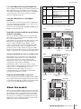
About the models
The CL series is available in three models: CL5, CL3, and
CL1. Each model features a different number of monaural
input channels and top-panel channel strips. In addition,
the CL5 features an Output Meter section. The CL3 and
CL1 allow you to install an optional MBCL meter bridge.
Other functions are common to all three models. Model
differences are shown in the table below.
NOTE
In this manual, most explanations refer to the CL5.
Monaural
input channels
Channel strips
Output
meters
CL5 72
Block A: 16
Block B (Centralogic section): 8
Block C: 8
MASTER section: 2
Ye s
CL3 64
Block A: 16
Block B (Centralogic section): 8
MASTER section: 2
Optional
MBCL
CL1 48
Block A: 8
Block B (Centralogic section): 8
MASTER section: 2
Optional
MBCL
Block A Centralogic section
(Block B)
Output meter
MASTER section
Block C
•CL5
Block A Centralogic section
(Block B)
MASTER section
Meter bridge
MBCL (optional)
•CL3
Block A Centralogic section
(Block B)
MASTER section
Meter bridge
MBCL (optional)
•CL1

Controls and functions
Owner’s Manual
10
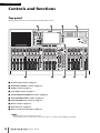
Controls and functions
Top panel
The top panel of the CL series is divided into the following sections.
1 Channel Strip section ➔ page 11
2 SELECTED CHANNEL section ➔ page 12
3 Display section ➔ page 13
4 Centralogic section ➔ page 13
5 SCENE MEMORY/MONITOR section ➔ page 14
6 USER DEFINED KNOBS section ➔ page 14
7 USER DEFINED KEYS section ➔ page 14
8 Master section ➔ page 15
9 USB connector ➔ page 15
0 Meter section (for CL5 only) ➔ page 15
NOTE
This illustration shows the top panel of the CL5.
The CL3 and CL1 do not feature a Meter section, but enable you to install an optional MBCL meter bridge.
236j
118
5
9
47

Top panel
Owner’s Manual
11
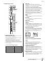
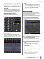
Channel Strip section
1 GAIN/PAN/ASSIGN knob
Adjusts the gain or pan of the channel. You can also
assign a parameter to this knob.
You can switch the function of the knob by using the
9 [GAIN/PAN/ASSIGN] key.
A gain parameter value indicated on the display or
channel name display indicates the amount of
amplification of a currently-input signal. Refer to the
Conversion Table for information on the relationship
to input sensitivity.
Conversion Table for Input Sensitivity
2 [SEL] key
Selects a channel that will be controlled in the
Channel Strip section and on the touch screen. When
a channel is selected, the key LED will light.
If you control an ST IN channel in Block A of the
Channel Strip section, the L channel will be routed to
an odd-numbered channel, and the R channel will be
routed to the adjacent even-numbered channel.
If you control a channel in the CUSTOM bank or in
Block C of the Channel Strip section, and if you assign
L/R channels, the selected object of control will
alternate between the L and R channels each time you
press the [SEL] key.
NOTE
If you assign either the L or R channel, this key will simply
select the channel.
3 [CUE] key
Selects the channel to be cue-monitored. If the cue is
on, the key LED will light.
4 Meter LEDs
Indicate the channel level.
5 [ON] key
Switches the channel on or off. If a channel is on, the
key LED will light. In SENDS ON FADER mode, this
is an on/off switch for signals sent from each channel
to the currently-selected MIX/MATRIX bus.
6 Channel name display
Indicates the channel name, knob value, fader value,
etc. You can set the display so that it will indicate only
the channel name. Use the PREFERENCE tab in the
USER SETUP screen to select information to be
displayed.
7 Channel color indicator
Lights in a color specified on the PATCH/NAME
screen. You can select the channel color from eight
options.
8 Fader
Adjusts the input/output level of the channel. In
SENDS ON FADER mode, this fader adjusts the send
level of the signal from each channel to the
currently-selected MIX/MATRIX bus.
9 [GAIN/PAN/ASSIGN] key
Switches the knob function for each block on the
channel strip. The LED for the selected function will
light. Use the USER DEFINED KNOBS tab in the
USER SETUP screen to select a parameter to control
when the ASSIGN function is selected.
0 Bank Select keys
These keys switch the channel faders controlled in the
Channel Strip section. The [CUSTOM] keys enable
you to select your own custom fader bank. For details
on the custom fader banks, refer to page 47.
Gain Input Sensitivity
–6dB +10dBu
::
0 +4dBu
::
+66dB –62dBu
1
2
3
4
5
6
7
8
9
j

Controls and functions
Owner’s Manual
12
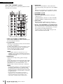
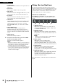
SELECTED CHANNEL section
This section enables you to set the mix parameters for the
currently-selected channel.
1 [MIX1–16] key/[MIX17–24/MATRIX] key
Select a MIX or MATRIX bus that is controlled by the
knobs located below the keys.
2 [1]–[16] knobs
Adjust the send level from currently-selected channels
to the MIX or MATRIX bus.
In SENDS ON FADER mode, push in a knob to select
the corresponding destination bus. Push the knob
again to turn the cue monitor on for the
corresponding MIX/MATRIX channel.
NOTE
If the SIGNAL TYPE of the destination bus is set to
STEREO, use the left knobs (odd-numbered channels) to
adjust PAN and the right knobs (even-numbered channels)
to adjust the send level.
3 [GAIN] knob
Adjusts the head amp’s analog gain for an input
channel.
On the other hand, it adjusts the digital gain if GAIN
KNOB FUNCTION is set to DIGITAL GAIN in the
PREFERENCE tab of the USER SETUP screen.
This knob has no effect for other types of channels.
NOTE
• The PAD will be switched on or off internally when the HA
analog gain is adjusted between +17 dB and +18 dB.
Keep in mind that noise may be generated when using
phantom power if there is a difference between the Hot and
Cold output impedance of an external device connected to
the INPUT connector.
• The gain parameter value indicates the amount of
amplification of the currently-input signal. Refer to the
Conversion Table (page 11) for information on the
relationship to conventional input sensitivity values.
4 [PAN] knob
When a monaural channel is selected, this knob
adjusts the panning of the signal sent to the STEREO
bus.
When a stereo channel is selected, this knob adjusts
the PAN or left/right balance, whichever is selected.
5 [DYNAMICS 1] knob
6 [DYNAMICS 2] knob
Adjust the THRESHOLD parameter of the gate,
compressor, etc.
The [DYNAMICS 2] knob has no effect if the MIX,
MATRIX, STEREO, or MONO channel is selected.
7 [HPF] knob
Adjusts the HPF cutoff frequency for an input
channel. It has no effect on other types of channels.
8 EQ [Q], EQ [FREQUENCY], EQ [GAIN] knobs
For each band of the four-band EQ, these knobs adjust
the Q, center frequency (cutoff frequency), and gain.
Press the EQ [Q] and EQ [GAIN] knobs
simultaneously to reset the GAIN setting for each
band to the default value (0.0 dB).
5
6
7
1
2
34
8

Top panel
Owner’s Manual
13
Display section
This is a touch screen that you can operate by touching the
surface of the screen. You can touch your finger to the
screen to select menus or set parameters. Please note that
you cannot operate the unit by touching multiple points
simultaneously.
NOTE
If the touch screen becomes dirty, wipe it with a soft dry
cloth.
NOTICE
Never use a sharp or pointed object such as your fingernail
to operate the touch panel. Doing so may scratch the
screen and render the touch screen inoperable.
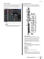
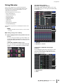
Centralogic section
This section enables you to control up to eight channel
modules that are selected from channel groups, DCA
groups, or custom groups selected by the Bank Select keys.
1 Bank Select keys
Select a bank to be controlled in the Centralogic
section. Press the [INPUT] key, then press one of the
Bank Select keys below to route the channel bank
(labeled to the left of the key) to the Centralogic
section. Press the [OUTPUT] key, then press one of
the Bank Select keys below to route the channel
(labeled to the right of the key) to the Centralogic
section.
2 Multifunction knob
Controls the knob currently selected on the touch
screen. The knob function can vary depending on the
screen currently displayed.
3 [SEL] key
4 [CUE] key
5 Meter LEDs
Same as those in the Channel Strip section.
6 [ON] key
Switches the channel on or off. If a channel is on, the
key LED will light. In SENDS ON FADER mode, this
is an on/off switch for signals sent from each channel
2
3
4
5
6
7
8
9
1

Controls and functions
Owner’s Manual
14
to the currently-selected MIX/MATRIX bus. If the
graphic EQ is used, this key resets the gain to 0 dB.
7 Channel name display
8 Channel color indicator
Same as that in the Channel Strip section. If the
graphic EQ is used, this indicator displays the
frequency and gain parameter value.
9 Fader
Adjusts the input/output level of the channel. You can
also make internal settings so that the fader will be
used as a controller to adjust the gain of each GEQ
band.
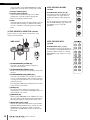
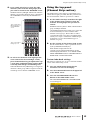
SCENE MEMORY/MONITOR section
In this section you can perform operations for scene
memory and monitoring.
1 SCENE MEMORY [STORE] key
Stores the current mix parameter settings in a
dedicated scene memory.
2 SCENE MEMORY [RECALL] key
Recalls a scene (previously-saved settings) from scene
memory.
3 SCENE MEMORY [INC]/[DEC] keys
Select the scene number of a scene that you want to
store or recall. The number of the currently-selected
scene appears in the function access area on the right
of the touch screen.
Press the [INC]/[DEC] keys simultaneously to return
to the current scene number.
4 [UNDO] key
Cancels the scene recall and recovers the status
obtained prior to recall. The key LED lights if you can
still cancel the scene recall.
5 [PREVIEW] key
This key selects PREVIEW mode, which lets you view
the scene settings in the display and the panel without
affecting the signal processing of the current scene.
6 [MONITOR LEVEL] knob
Adjusts the signal level of the monitor output. If the
PHONES LEVEL LINK function is turned on in the
MONITOR screen, this knob will also adjust the
signal level at the PHONES Out jack located on the
front panel.
USER DEFINED KNOBS
section
USER DEFINED knobs [A]–[D]
Control the parameters that have been
assigned by the user (input channel
digital gain, high-pass filter frequency,
etc.).
You can assign various parameters at will.
Use the USER SETUP popup window in
the SETUP screen to assign the
parameters.
USER DEFINED KEYS
section
USER DEFINED keys [1]–[16]
Execute functions as assigned by the user
(scene changes, switching the talkback or
internal oscillator on/off, etc.). Use the
USER SETUP popup window to assign
functions.
45
126
3

Top panel
Owner’s Manual
15
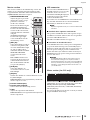
Master section
This section is similar to the Channel Strip section, and
enables you to control the principal parameters of the
assigned channels. When the unit is in the default state,
STEREO/MONO channels are assigned.
1 GAIN/PAN/ASSIGN knob
Adjusts the gain or pan of the
channel. You can also assign
parameters to the knob.
On the CL5, switch the
function of the knob using the
[GAIN/PAN/ASSIGN] key
located to the left of the Master
section. On the CL3 and CL1,
switch the function of the knob
using the
[GAIN/PAN/ASSIGN] key
located in the upper right
corner of the Block A in the
Channel Strip section.
2 [SEL] key
Selects the channel you wish to
control. Pressing this key will
cause the channel LED to light
up, and you will be able to
control the channel in both the
SELECTED CHANNEL
section and on the touch
screen.
If the STEREO bus has been
assigned, the selected object of
control will alternate between
the L and R channels each time
you press the [SEL] key.
3 [CUE] key
Selects the channel to be
cue-monitored. If cue is on, the
LED will light.
4 [ON] key
Switches the channel on or off. If a channel is on, the
key LED will light.
If MONITOR has been assigned, this key switches the
monitor output on or off.
5 Channel name display
6 Channel color indicator
Same as that in the Channel Strip section.
7 Fader
Adjusts the output level of the channel.
If MONITOR has been assigned, this fader adjusts the
monitor output level.
USB connector
You can connect a USB flash drive to
the USB connector to record or play
audio files, and to save or load
internal data. The Help file displayed
on the unit screen is loaded from a
connected USB flash drive.
You can also save on a USB flash drive “User authentication
key” data that determines the user level and limit the
functionality to which the user has access.
NOTE
Operation is guaranteed only for a connection with a USB
flash drive.
■ USB flash drive capacities and formats
The operation of USB flash drives with capacities of up to
32 GB has been verified. (However, this does not guarantee
operation of all USB flash drives.)
The FAT16 and FAT32 formats are supported.
■ Prevention of accidental erasure
Some USB flash drives have a write-protect setting that lets
you prevent data from being erased accidentally. If your
flash drive contains important data, it is a good idea to use
the write-protect setting to prevent accidental erasure.
On the other hand, you will need to make sure that your
USB flash drive’s write-protect setting is turned off before
you save data onto it.
NOTICE
An ACCESS indicator appears in the Function Access
Area while data is being accessed (saved, loaded, or
deleted). During this time, do not disconnect the USB flash
drive or power-off the CL unit. Doing so may damage your
flash drive, or may damage the data in the CL unit or on
your media device.
Meter section (for CL5 only)
Indicates the level of MIX/MATRIX, STEREO/MONO and
CUE channels. You can select the monitoring position from
PRE EQ (immediately before EQ), PRE FADER
(immediately before the fader), or POST ON (immediately
after the [ON] key).
You can use this function on the CL3 or CL1 if you install
an optional MBCL meter bridge.
1
2
3
4
7
5
6

Controls and functions
Owner’s Manual
16
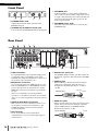
Front Panel
1 PHONES LEVEL knob
Adjusts the level of the signal output from the
PHONES Out jack.
2 PHONES Out (headphone output) jack
Lets you monitor the MONITOR OUT or CUE signal.
3 TALKBACK jack
A balanced XLR-3-31 jack to which a talkback mic
can be connected. You can make settings in the screen
to supply +48V phantom power to this jack. This jack
sends instructions from the mixer operator to the
desired output channel.
4 TALKBACK LEVEL knob
Adjusts the input level of the mic connected to the
TALKBACK jack.
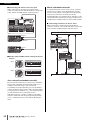
Rear Panel
1 LAMP connectors
Four-pin female XLR output jacks that supply power
to separately-sold gooseneck lamps (such as the
Yamaha LA1L). (The CL3 includes these connectors at
two locations. The CL1 includes one.)
2 MIDI IN/OUT connectors
Used to transmit and receive MIDI messages to and
from external MIDI devices. The MIDI IN connector
receives messages from an external device, and the
MIDI OUT connector transmits messages from the
CL unit.
These are used mainly to record CL parameter
operations or scene/library selections on an external
device, or to control CL parameters from an external
device.
3 WORD CLOCK IN/OUT connectors
BNC connectors used to transmit and receive word
clock signals to and from an external device. The
WORD CLOCK IN connector features internal
75-ohm termination.
4 GPI connector
D-sub 15-pin female connector that allows
communication (5-in/5-out) with a GPI-equipped
external device.
5 DIGITAL OUT connector
An AES/EBU (XLR-3-32 male) jack that outputs the
digital audio signal of a desired channel in AES/EBU
format.
6 OMNI IN jacks
Balanced XLR-3-31 female input jacks that input
analog audio signals from line level devices or
microphones. Nominal input level is −62 dBu to
+10 dBu.
7 OMNI OUT jacks
XLR-3-32 male output jacks that output analog audio
signals. These jacks are used mainly to output the
signals of MIX channels or MATRIX channels.
Nominal output level is +4 dBu.
12 34
21 3 4 5
876 A90 C D FEB
Male XLR plug
1 (Ground)
3 (Cold)
2 (Hot)
Female XLR plug
1 (Ground)
3 (Cold)
2 (Hot)

Rear Panel
Owner’s Manual
17
NOTE
Although OMNI OUT jacks feature a nominal input/output
level of +4 dBu (maximum level +24 dBu), an internal
switch allows this to be changed to –2 dBu (maximum level
+18 dBu) if necessary. (A fee will be charged for this
procedure.) For details, contact your Yamaha dealer.
8 Dante PRIMARY/SECONDARY connectors
Used to connect to other Dante-compatible network
devices, such as an Rio3224-D I/O device.
Use standard Ethernet cables with Neutrik etherCON
CAT5 compatible RJ-45 plugs.
NOTE
Use STP (shielded twisted pair) cable to prevent
electromagnetic interference. Make sure that the metal
parts of the plugs are electrically connected to the STP
cable shield by conductive tape or comparable means.
9 LINK/ACT Indicators
These indicators show the communication status of
the PRIMARY and SECONDARY connectors.
They flash fast if the Ethernet cables are connected
properly.
0 1G Indicators
These indicators light when the Dante network is
functioning as Giga-bit Ethernet.
A NETWORK connector
Allows the CL unit to be connected to a computer via
an Ethernet cable (CAT5e or higher recommended).
This connector is used mainly to control mix
parameters or to edit scene memories and libraries
from the dedicated “CL Editor” application program
or “StageMix” iPad application.
NOTE
Use STP (shielded twisted pair) cable to prevent
electromagnetic interference. Make sure that the metal
parts of the plugs are electrically connected to the STP
cable shield by conductive tape or comparable means.
B SLOT 1–3
Allow for the installation of separately-sold DSP
cards, or mini-YGDAI I/O cards to expand the
number of input/output ports.
C DC POWER INPUT connector
You can connect the separately-sold PW800W power
supply here as a backup external power supply. If the
PW800W is connected, the CL unit will continue
receiving power from the PW800W, even if its own
internal power supply shuts down due to a problem.
Caution
If you plan to connect the PW800W, be sure to first
power-off both the CL unit and the PW800W. Then, use the
power supply cable (PSL360) to make the connection.
Failure to observe this caution may cause malfunction or
electric shock.
NOTE
• If a PW800W is connected, the CL series will operate
correctly whether its own internal power supply and the
PW800W are both turned on, or just one of them is turned
on.
• If both power supplies are turned on, and an abnormality
is detected in one of the power supplies, the CL series will
automatically switch to the other power supply. If this
occurs, the touch screen will display a message to inform
you.
D AC IN connector
Connect the supplied AC power cable here. First
connect the AC power cable to the CL unit, then insert
the power cable plug into an AC power outlet.
The supplied AC power cable features a special
latching mechanism (V-LOCK) to prevent the power
cable from being disconnected accidentally.
Connect the power cable by inserting the cable plug
fully until it is locked.
Caution
Be sure to turn the power off before connecting or
disconnecting the power cable.
To disconnect the power
cable, press the latch button
on the plug.
E (Power Switch)
This switch turns power on or off. When the power
switch is set to , the power to the unit is on. When
the power switch is set to , the power to the unit is
off.
Caution
• Rapidly turning the unit on and off in succession can cause
it to malfunction. After turning the unit off, wait for at least 6
seconds before turning it on again.
• Even when the power switch is turned off, a small amount
of current is flowing through the unit. If you plan not to use
the unit for a long period of time, remove the power cable
from the AC outlet.
F Grounding screw
The supplied AC power cable is a 3-wire type.
Therefore, if the AC outlet used is properly grounded,
the CL will be grounded as well. Also, grounding this
screw may effectively eliminate noise such as hum and
interference.

Touch screen
Owner’s Manual
18
Touch screen
Basic touch screen
operations
This section explains the basic procedures you can perform
on the CL’s touch screen. In general, you will operate the CL
using an appropriate combination of the operations
explained here.
Pressing the touch screen
You will mainly use this operation to switch screens and
pages, to select a parameter to operate, and to turn a button
on or off. Certain buttons let you specify a number based
on the area of the button itself that you touch.
Multiple selection (specifying a range)
While pressing your finger on the touch panel, move it in
the left or right direction to specify a range within a
character string. You will use this technique primarily
when assigning a name to a scene or library.
For the channel select buttons, you can select multiple
buttons by moving your finger across the touch screen
while continuing to press down.
NOTE
This makes it easy to select a range of buttons to be turned
on or off together.
Special key operations
Typically, you will press a top panel key once, but in certain
cases you can access special functions by rapidly pressing a
key twice in succession.
Knob operations
Typically, knobs are rotated left or right to change the value
of the corresponding parameter. By pressing a knob, you
can recall a specific screen.
For certain parameters, you can adjust the value in finer
steps (greater detail) by rotating the knob while pressing it.
Multifunction knob operations
Multifunction knobs 1–8 are used to operate knobs
selected in the touch screen.
A thick line will be displayed around a selected knob if it
can be controlled by a multifunction knob. (Typically, a
knob of this type corresponds to the multifunction knob
located immediately below it and allows you to control up
to eight parameters simultaneously.)
While a knob is selected, turning the multifunction knob
located immediately below it will change the value of the
corresponding parameter.
In the SCENE LIST screen, you can select multiple items by
rotating a multifunction knob while pressing it.
The on-screen user interface
The section below explains various user interface
components that appear in the touch screen, and how to
use them.
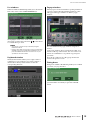
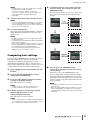
Tabs
Tabs enable you to switch between multiple pages. Each tab
indicates its page name.
Buttons
Buttons are used to execute specific functions, to switch
parameters on or off, or to select one of the multiple
choices. Buttons that perform on/off operations appear in
solid colors while they are turned on, and dark while when
turned off.
When you press a button labeled with two overlaid “■”
symbols or a “▼” mark, a separate window will open,
allowing you to make detailed settings.
Faders / Knobs
Faders and knobs on screen move in tandem when you
operate the top panel faders and knobs. The current value
appears immediately below the fader or knob.
If you press once a knob that can be operated by a
multifunction knob, a thick frame appears around the
knob. This frame indicates that the knob has been selected
for operation.
NOTE
Pressing certain knobs a second time while a thick frame
is displayed around them will open a window in which you
can make additional detailed settings.
Buttons
Ta bs

The on-screen user interface
Owner’s Manual
19
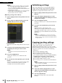
List windows
Windows similar to the following enable you to select items
from a list, such as a list of USER DEFINED keys.
The highlighted item in the middle indicates it has been
selected for operation. Press the arrow / below the list
to scroll the list up or down.
NOTE
• You can also scroll the list up or down by using the
multifunction knob.
• If there is more than one list on the screen, your operations
will apply to the list surrounded by a pink frame. You can
press the multifunction knob to move the focus of your
operations to the next column.
Keyboard window
The keyboard window enables you to assign a name or
comment to a scene or library, or to assign a name to a
channel. Press the keys in the window to enter the
corresponding character.
Popup windows
When you press a button or field for a specific parameter in
a screen, a window showing detailed parameters or lists
will appear. This type of window is called a “popup
window.”
You can switch between popup windows using tabs as
needed.
Some popup windows show several buttons called “tool
buttons” at the top of the window. You can use these tool
buttons to recall libraries or to perform copy and paste
operations.
Press the “X” symbol to close the popup window and
return to the previous screen.
Dialog boxes
Dialog boxes similar to the following enable you to confirm
operations you just performed.
Press the OK button to execute the operation. The
operation will be canceled if you press the CANCEL
button.

Touch screen
Owner’s Manual
20
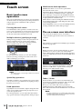
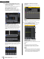
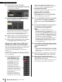
Viewing the touch screen
The touch screen of the CL series is broadly divided into
two areas.
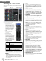
Function access area
1 Selected channel
This field indicates the number,
name, icon and channel color
of the channel that is currently
selected for operation. Press the
left half of the selected channel
to switch to the preceding
channel; press the right half to
switch to the next channel.
2 Time
This area indicates the
current time.
3 Status Indicator
This area indicates the
current unit status. Normally
it indicates the name of the
user who is currently logged
in (i.e., is authenticated and
able to operate the system).
The following table shows the
indications and their
corresponding status.
*1 The signal type (IN/OUT/DCA/KEYIN/EFFECT) is shown in the
upper part of the CUE meter.
*2
This indicator appears when the operation switches from the primary
to the secondary Dante audio network in a redundant connection
.
NOTICE
An ACCESS indicator appears in the Function Access
Area while data is being accessed (saved, loaded, or
deleted). During this time, do not disconnect the USB flash
drive or power-off the CL unit. Doing so may damage your
flash drive, or may damage the data in the CL unit or on
your media device.
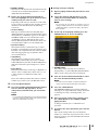
4 HELP
Pressing this button will show on-line help in the
main area. To view the on-line Help, first you must
load the Help file from a USB flash drive. Once the
Help file has been loaded, it will be kept in internal
memory.
5 SENDS ON FADER
Press this button to switch to SENDS ON FADER mode,
where you can use the faders of the top panel to adjust
the MIX/MATRIX send level. During this time, the
function access area will switch to a screen that enables
you to select the send-destination MIX/MATRIX bus.
6 I/O DEVICE
When you press this button, the I/O DEVICE screen
will appear in the main area, allowing you to make
settings for I/O devices and external head amps.
7 CH JOB (Channel Job)
When you press this button, the CH JOB menu which
allows you to group and link channels will appear,
allowing you to select the function you want to operate.
8 RACK
When you press this button, the VIRTUAL RACK
screen will appear in the main area, allowing you to
edit the GEQ and effect settings.
9 MONITOR
When you press this button, the MONITOR screen
will appear in the main area, allowing you to edit the
monitor or oscillator settings.
0 METER
These are level meters that show the level of the
STEREO bus (L/R), MONO bus (M), and cue signal
(CUE). When you press this field, the METER screen
will appear in the main area. If you press part of the
CUE meters when the cue monitor is on, the cue
monitor will be canceled.
A SETUP
When you press this button, the SETUP screen will
appear in the main area, allowing you to make basic
system settings and user-specific settings.
B RECORDER
When you press this button, the recorder screen will
appear in the main area, allowing you to operate and
set up the recorder function (USB/Nuendo Live) for
audio recording and playback.
C SCENE
This area indicates the number and title of the scene
that was last stored or recalled. An “R” symbol is
displayed for read-only scenes, and a lock icon is
displayed for write-protected scenes. If you edit the
parameters from their last stored or recalled state, an
“E” symbol will appear in the lower right. When you
press this field, the SCENE LIST screen will appear in
the main area, allowing you to store or recall scenes.
In PREVIEW mode, this field is shown in red.
D USER DEFINED KEY
This area indicates the bank for the USER DEFINED
key that is currently selected.
Indication Status
OSC Oscillator enabled
TALKBACK Talkback enabled
CUE Cue monitor on*
1
ACCESS Accessing internal memory or USB memory
PATCHING Now performing Dante patching
ALT ALTERNATE mode enabled
PLAY Playing an audio file
REC Recording an audio file
SECONDARY
Switching to the secondary network
*2
Function access areaMain area
1
2
3
8
6
4
5
7
9
k
l
n
m
j
Sayfa yükleniyor...
Sayfa yükleniyor...
Sayfa yükleniyor...
Sayfa yükleniyor...
Sayfa yükleniyor...
Sayfa yükleniyor...
Sayfa yükleniyor...
Sayfa yükleniyor...
Sayfa yükleniyor...
Sayfa yükleniyor...
Sayfa yükleniyor...
Sayfa yükleniyor...
Sayfa yükleniyor...
Sayfa yükleniyor...
Sayfa yükleniyor...
Sayfa yükleniyor...
Sayfa yükleniyor...
Sayfa yükleniyor...
Sayfa yükleniyor...
Sayfa yükleniyor...
Sayfa yükleniyor...
Sayfa yükleniyor...
Sayfa yükleniyor...
Sayfa yükleniyor...
Sayfa yükleniyor...
Sayfa yükleniyor...
Sayfa yükleniyor...
Sayfa yükleniyor...
Sayfa yükleniyor...
Sayfa yükleniyor...
Sayfa yükleniyor...
Sayfa yükleniyor...
Sayfa yükleniyor...
Sayfa yükleniyor...
Sayfa yükleniyor...
Sayfa yükleniyor...
Sayfa yükleniyor...
Sayfa yükleniyor...
Sayfa yükleniyor...
Sayfa yükleniyor...
Sayfa yükleniyor...
Sayfa yükleniyor...
Sayfa yükleniyor...
Sayfa yükleniyor...
Sayfa yükleniyor...
Sayfa yükleniyor...
Sayfa yükleniyor...
-
 1
1
-
 2
2
-
 3
3
-
 4
4
-
 5
5
-
 6
6
-
 7
7
-
 8
8
-
 9
9
-
 10
10
-
 11
11
-
 12
12
-
 13
13
-
 14
14
-
 15
15
-
 16
16
-
 17
17
-
 18
18
-
 19
19
-
 20
20
-
 21
21
-
 22
22
-
 23
23
-
 24
24
-
 25
25
-
 26
26
-
 27
27
-
 28
28
-
 29
29
-
 30
30
-
 31
31
-
 32
32
-
 33
33
-
 34
34
-
 35
35
-
 36
36
-
 37
37
-
 38
38
-
 39
39
-
 40
40
-
 41
41
-
 42
42
-
 43
43
-
 44
44
-
 45
45
-
 46
46
-
 47
47
-
 48
48
-
 49
49
-
 50
50
-
 51
51
-
 52
52
-
 53
53
-
 54
54
-
 55
55
-
 56
56
-
 57
57
-
 58
58
-
 59
59
-
 60
60
-
 61
61
-
 62
62
-
 63
63
-
 64
64
-
 65
65
-
 66
66
-
 67
67


Yamaha CL1 El kitabı
- Kategori
- Ses mikserleri
- Tip
- El kitabı
diğer dillerde
- español: Yamaha CL1 El manual del propietario
- français: Yamaha CL1 Le manuel du propriétaire
- italiano: Yamaha CL1 Manuale del proprietario
- svenska: Yamaha CL1 Bruksanvisning
- čeština: Yamaha CL1 Návod k obsluze
- polski: Yamaha CL1 Instrukcja obsługi
- Deutsch: Yamaha CL1 Bedienungsanleitung
- português: Yamaha CL1 Manual do proprietário
- English: Yamaha CL1 Owner's manual
- dansk: Yamaha CL1 Brugervejledning
- русский: Yamaha CL1 Инструкция по применению
- suomi: Yamaha CL1 Omistajan opas
- Nederlands: Yamaha CL1 de handleiding
- română: Yamaha CL1 Manualul proprietarului