Hitachi DS 12DVF3 Handling Instructions Manual
- Kategori
- Elektrikli aletler
- Tip
- Handling Instructions Manual

Variable speed
DS 9DVF3
•
DS 12DVF3
DS 14DVF3
•
DS 18DVF3
DS18DVF3
Cordless Driver Drill
Akku-Bohrschrauber
∆ραπανκατσάιδ µπαταρίας
Wiertarko-wkrętarka akumulatorowa
Akkus fúró-csavarozó
Akku vrtací šroubovák
Akülü vidalama matkap
Mașină de găurit și înșurubat cu acumulator
Akumulatorski udarni vrtalnik
Akku vrtací skrutkovač
Акумуляторний шуруповерт
Аккумуляторный шуруповерт
Read through carefully and understand these instructions before use.
Diese Anleitung vor Benutzung des Werkzeugs sorgfältig durchlesen und verstehen.
¢È·‚¿ÛÙ ÚÔÛÂÎÙÈο Î·È Î·Ù·ÓÔ‹ÛÂÙ ·˘Ù¤˜ ÙȘ Ô‰ËÁ›Â˜ ÚÈÓ ÙË ¯Ú‹ÛË.
Przed użytkowaniem należy dokładnie przeczytać niniejszą instrukcję i zrozumieć jej treść.
Használat előtt olvassa el figyelmesen a használati utasítást.
Před použitím si pečlivě přečtěte tento návod a ujistěte se, že mu dobře rozumíte.
Aleti kullanmadan önce bu kılavuzu iyice okuyun ve talimatları anlayın.
Înainte de utilizare, citiţi cu atenţie și înţelegeţi prezentele instrucţiuni.
Pred uporabo natančno preberite in razumite ta navodila.
Pred použitím si dôkladne tieto pokyny prečítajte a pochopte ich.
Будь ласка, прочитайте інструкції і перевірте себе, чи все зрозуміло, перш ніж користуватися приладом.
BÌËÏaÚeÎëÌo ÔpoäÚËÚe ÀaÌÌyï ËÌcÚpyÍáËï Ôo íÍcÔÎyaÚaáËË ÔpeÊÀe äeÏ ÔoÎëÁoÇaÚëcÓ ËÌcÚpyÏeÌÚoÏ.
Handling instructions
Bedienungsanleitung
√‰ËÁ›Â˜ ¯ÂÈÚÈÛÌÔ‡
Instrukcja obsługi
Kezelési utasítás
Návod k obsluze
Kullanım talimatları
Instrucţiuni de utilizare
Navodila za rokovanje
Pokyny na manipuláciu
lнструкції щодо поводження з пристроєм
àÌcÚpyÍáËÓ Ôo íÍcÔÎyaÚaáËË
000Cover_DS9DVF3_EE 2/22/13, 16:521

2
45355251
12
34
8
7
5
6
9
8
7
6
9
5
1
A
2
0
B
1
2
3
4
0
B
A
D
E
F
G
C
C
E
H
I
J
I
K
4
6
3
5
7
21
8
00Table_DS9DVF3_EE 2/22/13, 16:492

3
S
U
T
U
2
3
4
5
(A)
(B)
1
O
LM
N
P
R
Q
V
W
X
V
Y
V
12
14
11
13
15
109
16
00Table_DS9DVF3_EE 2/22/13, 16:493

4
Z
b
a
c
d
c
b
Z
Z
]
^
a
[
\
20
22
19
21
1817
00Table_DS9DVF3_EE 2/22/13, 16:494

5
1
2
3
4
5
6
7
8
9
0
A
B
C
D
E
F
G
H
I
J
K
L
M
N
O
P
Q
R
S
T
U
V
W
X
Y
Z
[
\
]
`
a
b
c
d
English Deutsch Ελληνικά Polski
9.6 V Rechargeable
battery (For DS9DVF3)
12 V Rechargeable
battery (For DS12DVF3)
14.4 V Rechargeable
battery (For DS14DVF3)
18 V Rechargeable
battery (For DS18DVF3)
Latch
Pull out
Insert
Handle
Push
Insert
Pilot lamp
Hole for connecting the
rechargeable battery
Drill mark
Clutch dial
Triangle mark
Weak
Strong
Line
Shift knob
Low speed
High speed
Ring
Sleeve
Tighten
Loosen
Sleeve
Tighten
Loosen
Trigger switch
Selector button
R
and
L
marks
Hook
Loosen
Spring
Larger diameter faces
away
Hook with light
Switch
Phillips-head screwdriver
Screw
Arrow
Hook cover
Indentation
Protuberance
AAAA batteries
9,6 V aufladbare Batterie
(Für DS9DVF3)
12 V aufladbare Batterie
(Für DS12DVF3)
14,4 V aufladbare
Batterie (Für DS14DVF3)
18 V aufladbare Batterie
(Für DS18DVF3)
Verriegelung
Herausziehen
Einsetzen
Handgriff
Drücken
Einsetzen
Kontrollampe
Anschlußloch für
Ladebatterir
Bohrer-Zeichen
Kupplungsskala
Dreiecksmarkierung
Schwach
Stark
Linie
Schaltknopf
Kleine Geschwindigkeit
Große Geschwindigkeit
Ring
Manschette
Anziehen
Lösen
Manschette
Anziehen
Lösen
Trigger
Wählhebel
R
und
L
Zeichen
Haken
Lösen
Feder
Der große Durchmesser
weist zur anderen Seite
Haken mit Beleuchtung
Schalter
Kreuzschlitzschrauben-
zieher
Schraube
Pfeil
Hakenabdeckung
Einkerbung
Vorsprung
Batterien der Größe
AAAA
9,6 V Επαναρτιµενη
µπαταρία (Για DS9DVF3)
12 V Επαναρτιµενη
µπαταρία (Για DS12DVF3)
14,4 V Επαναρτιµενη
µπαταρία (Για DS14DVF3)
18 V Επαναρτιµενη
µπαταρία (Για DS18DVF3)
Μάνδαλ
Τραήτε έω
Εισωρήστε
ερύλι
Σπρώετε
Εισωρήσετε
∆κιµαστική λάµπα
Τρύπα για την σύνδεση
της επαναρτιµενης
µπαταρίας
Σηµάδι τρυπανιύ
Καντράν συµπλέκτη
Σηµάδι τριγώνυ
Αδύνατ
∆υνατ
Γραµµή
Κυµπί αλλαγής
αµηλή ταύτητα
Υψηλή ταύτητα
∆ακτύλις
Περίληµα
Σίτε
αλαρώστε
Περίληµα
Σίτε
αλαρώστε
Σκανδάλη διακπτης
Κυµπί επιλγέα
R
και
L
σηµάδια
Γάντς
Xαλαρώστε
Ελατήρι
Η µεγαλύτερη
διάµετρς λέπει πρς
άλλη κατεύθυνση
Γάντς µε ως
∆ιακπτης
Κατσαίδι κεαλής
Phillips
Βίδα
Βέλς
Κάλυµµα αγκίστρυ
Αυλάκωση
Πρεή
ΑΑΑΑ µπαταρίες
Akumulator 9,6 V
(do DS9DVF3)
Akumulator 12 V
(do DS12DVF3)
Akumulator 14,4 V
(do DS14DVF3)
Akumulator 18 V
(do DS18DVF3)
Zapadka
Wyciągnij
Włóż/wprowadź
Rączka
Naciśnij
Włóż/wprowadź
Lampka kontrolna
Otwór wsuwowy
akumulatora
Symbol wiercenia
Pokrętło sprzęgła
Trójkątny symbol
Mały
Duży
Linia
Zmieniacz
Mała prędkość/niskie obroty
Duża prędkość/wysokie obroty
Pierścień
Tuleja
Zaciśnij
Zluzuj/zwolnij
Tuleja
Zaciśnij
Zluzuj/zwolnij
Spust
Przełącznik kierunku obrotów
Symbole
L
i
R
Hak
Zluzuj/zwolnij
Sprężyna
Większa średnica jest
odwrócona
Hak ze światłem
Przełącznik (włącznik/
wyłącznik)
Wkrętak Philipsa/z
gniazdkiem krzyżykowym
Śruba/wkręt
Strzałka
Pokrywa haka
Nacięcie
Wypukłość
Baterie AAAA
00Table_DS9DVF3_EE 2/22/13, 16:495

6
Magyar Čeština Türkçe Romanian
1
2
3
4
5
6
7
8
9
0
A
B
C
D
E
F
G
H
I
J
K
L
M
N
O
P
Q
R
S
T
U
V
W
X
Y
Z
[
\
]
`
a
b
c
d
9,6 V-os tölthető
akkumulátor (DS9DVF3-hez)
12 V-os tölthető
akkumulátor (DS12DVF3-hez)
14,4 V-os tölthető
akkumulátor (DS14DVF3-hez)
18 V-os tölthető
akkumulátor (DS18DVF3-hez)
Retesz
Kihúzni
Bedugni
Markolat
Benyomni
Bedugni
Jelzőlámpa
Nyílás a tölthető
akkumulátor
csatlakoztatásához
Fúró jel
Befogó szorító
Háromszög alakú jel
Gyenge
Erős
Vezeték
Váltógomb
Alacsony fordulatszám
Magas fordulatszám
Gyűrű
Karmantyú
Meghúzás
Kilazítás
Karmantyú
Meghúzás
Kilazítás
Kapcsoló ravasz
Választógomb
R
(Jobbra) és
L
(Balra) jelek
Kampó
Meglazítani
Rúgó
A nagyobb átmérő az
ellenkező irány felé néz
Kampó, lámpával
Kapcsoló
Keresztfejes (Phillips-)
csavarhúzó
Csavar
Nyíl
A kampó fedele
Bemélyedés
Kidudorodás
AAAA méretű szárazelemek
9,6 V Akumulátor
(Pro DS9DVF3)
12 V Akumulátor
(Pro DS12DVF3)
14,4 V Akumulátor
(Pro DS14DVF3)
18 V Akumulátor
(Pro DS18DVF3)
Zámek
Zatáhnout
Zasunout
Držadlo
Stisknout
Zasunout
Indikátor
Otvor pro zasunutí
akumulátoru
Značka vrtání
Stupnice spojky
Trojúhelníková značka
Slabě
Silně
Čára
Přepínač
Nízké otáčky
Vysoké otáčky
Kroužek
Objímka
Utáhnout
Povolit
Objímka
Utáhnout
Povolit
Tlačítkový spínač
Volba sméru
Značka pro
R
a
L
pohyb
Páčka
Povolit
Pružina
Větší průměr směřuje ven
Páčka a světlo
Spínač
Křížový šroubovák
Šroub
Šipka
Kryt páčky
Prohlubeň
Výstupek
AAAA baterie
9,6 V Íarj edilebilir batarya
(DS9DVF3 için)
12 V Íarj edilebilir batarya
(DS12DVF3 için)
14,4 V Íarj edilebilir
batarya (DS14DVF3 için)
18 V Íarj edilebilir batarya
(DS18DVF3 için)
Mandal
Çekin
Yerleßtirin
Kol
Ótin
Yerleßtirin
Kılavuz lamba
Íarj edilebilir bataryanın
takılacaåı delik
Matkap ißareti
Kavrama kadranı
Üçgen ißareti
Zayıf
Güçlü
Beyaz çizgi
Kaydırılan düåme
Düßük hız
Yüksek hız
Halka
Bilezik
Sıkın
Gevßetin
Bilezik
Sıkın
Gevßetin
Íalter tetiåi
Seçim düåmesi
R
ve
L
ißaretleri
Askı
Gevßetin
Yay
Büyük olan çap uzaåa
bakar
Ißıklı askı
Íalter
Yıldız baßlı tornavida
Vida
Ok
Askı kapaåı
Girinti
Çıkıntı
AAAA piller
Acumulator reîncărcabil
9,6 V (pentru DS9DVF3)
Acumulator reîncărcabil
12 V (pentru DS12DVF3)
Acumulator reîncărcabil
14,4 V (pentru DS14DVF3)
Acumulator reîncărcabil
18 V (pentru DS18DVF3)
Element de blocare
Trageţi
Introduceţi
Mâner
Împingeţi
Introduceţi
Lampă pilot
Orificiu pentru conectarea
acumulatorului reîncărcabil
Marcaj pentru găurire
Selector pentru cuplare
Marcaj triunghiular
Slab
Puternic
Linie
Buton de modificare
Viteză scăzută
Viteză ridicată
Inel
Manșon
Strângeţi
Slăbiţi
Manșon
Strângeţi
Slăbiţi
Buton declanșator
Buton pentru selectare
Marcaje
R
și
L
Element de prindere
Slăbiţi
Arc
Diametrul mare este
poziţionat spre exterior
Cârlig cu lumină
Comutator
Șurubelniţă cu cap Phillips
Șurub
Săgeată
Capac cârlig
Canelură
Proeminenţă
Baterii AAAA
00Table_DS9DVF3_EE 2/22/13, 16:496

7
Slovenščina Slovenčina Український PyccÍËÈ
1
2
3
4
5
6
7
8
9
0
A
B
C
D
E
F
G
H
I
J
K
L
M
N
O
P
Q
R
S
T
U
V
W
X
Y
Z
[
\
]
`
a
b
c
d
9,6 B aÍÍyÏyÎÓÚopÌaÓ
ÄaÚapeÓ (ÀÎÓ DS9DVF3)
12 B aÍÍyÏyÎÓÚopÌaÓ
ÄaÚapeÓ (ÀÎÓ DS12DVF3)
14,4 B aÍÍyÏyÎÓÚopÌaÓ
ÄaÚapeÓ (ÀÎÓ DS14DVF3)
18 B aÍÍyÏyÎÓÚopÌaÓ
ÄaÚapeÓ (ÀÎÓ DS18DVF3)
îËÍcaÚop
BêÚaçËÚë
BcÚaÇËÚë
PyÍoÓÚÍa
HaÊaÚë
BcÚaÇËÚë
KoÌÚpoÎëÌaÓ ÎaÏÔa
OÚÇepcÚËe ÀÎÓ
ÔoÀÍÎïäeÌËÓ
aÍÍyÏyÎÓÚopÌoÈ ÄaÚapeË
îaÄpËäÌoe ÍÎeÈÏo
ÑËcÍ ÏyÙÚê
TpeyÖoÎëÌaÓ ÏeÚÍa
HËÁÍËe oÄopoÚê
BêcoÍËe oÄopoÚê
ÅeÎaÓ ÎËÌËÓ
KÌoÔÍa ÔepeÍÎïäeÌËÓ
HËÁÍaÓ cÍopocÚë
BêcoÍaÓ cÍopocÚë
KoÎëáo
OÄoÀ
ÂaÚÓÌyÚë
OcÎaÄËÚë
OÄoÀ
ÂaÚÓÌyÚë
OcÎaÄËÚë
èycÍoÇoÈ ÔepeÍÎïäaÚeÎë
CeÎeÍÚopÌaÓ ÍÌoÔÍa
MeÚÍË
R
Ë
L
KpïäoÍ
OcÎaÄËÚë
èpyÊËÌa
ÅoÎëåËÈ ÀËaÏeÚp
ÔoÇopaäËÇaeÚcÓ Ç ÀpyÖyï
cÚopoÌy
KpïäoÍ c ÔoÀcÇeÚÍoÈ
BêÍÎïäaÚeÎë
OÚÇepÚÍa c
ÍpecÚooÄpaÁÌoÈ ÖoÎoÇÍoÈ
BËÌÚ
CÚpeÎÍa
KpêåÍa ÍpïäÍa
ìÖÎyÄÎeÌËe
BêcÚyÔ
AÍÍyÏyÎÓÚopÌêe ÄaÚapeË
AAAA
9,6 V polnilni akumulator
(za DS9DVF3)
12 V polnilni akumulator
(za DS12DVF3)
14,4 V polnilni akumulator
(za DS14DVF3)
18 V polnilni akumulator
(za DS18DVF3)
Zapah
Izvlecite
Vstavite
Ročica
Potisniti
Vstavite
Kontrolni svetlobni indikator
Luknja za priključevanje
baterije, ki se polni
Označba za vrtanje
Številčnica sklopke
Trikotna označba
Slabo
Močno
Linija
Preklopni gumb
Nizka hitrost
Visoka hitrost
Obroček
Rokav
Zatesnite
Odvijte
Rokav
Zatesnite
Odvijte
Sprožilno stikalo
Izbirna tipka
Označbi za
R
in
L
Kljuka
Odvijte
Vzmet
Večji premer obrnjen stran
Kljuka z lučko
Stikalo
Izvijač s Phillipsovo glavo
Vijak
Puščica
Pokrov kljuke
Zareza
Ibočina
AAAA baterije
9,6 V nabíjatený akumulátor
(pre DS9DVF3)
12 V nabíjatený akumulátor
(pre DS12DVF3)
14,4 V nabíjatený akumulátor
(pre DS14DVF3)
18 V nabíjatený akumulátor
(pre DS18DVF3)
Západka
Vytiahnu
Zasunú
Rukovä
Stlači
Zasunú
Kontrolka
Otvor na pripojenie
nabíjatenej batérie
Značka vŕtačky
Číselník spojky
Znak trojuholníka
Slabý
Silný
Čiara
Prepínač
Nízka rýchlos
Vysoká rýchlos
Krúžok
Objímka
Utiahnu
Uvoni
Objímka
Utiahnu
Uvoni
Spúšací spínač
Voliace tlačidlo
Značky
R
a
L
Hák
Uvoni
Pružina
Väčší priemer je
otočený smerom von
Hák s osvetlením
Spínač
Krížový skrutkovač
Skrutka
Šípka
Kryt háka
Drážka
Výčnelok
Batérie AAAA
9,6 В Акумуляторна
батарея (для DS9DVF3)
12 В Акумуляторна
батарея (для DS12DVF3)
14,4 В В Акумуляторна
батарея (для DS14DVF3)
18 В Акумуляторна
батарея (для DS18DVF3)
Фіксатор
Витягнути
Вставити
Рукоятка
Натиснути
Вставити
Контрольна лампа
Отвір для під'єднання
акумуляторної батареї
Фабричне клеймо
Диск муфти
Трикутна мітка
Низькі обороти
Високі обороти
Біла лінія
Кнопка перемикання
Низька швидкість
Висока швидкість
Кільце
Обід
Затягнути
Послабити
Обід
Затягнути
Послабити
Пусковий перемикач
Селекторна кнопка
Мітки
R
і
L
Гачок
Послабити
Пружина
Більший діаметр
обернений убік
Гачок із ліхтариком
Вимикач
Хрестова икрутка
Гвинт
Стрілка
Кришка гачка
Заглиблення
Виступ
Акумуляторні батареї
АААА
00Table_DS9DVF3_EE 2/22/13, 16:497

8
Symbols
WARNING
The following show symbols
used for the machine. Be sure
that you understand their
meaning before use.
Symbole
WARNUNG
Die folgenden Symbole werden
für diese Maschine verwendet.
Achten Sie darauf, diese vor der
Verwendung zu verstehen.
™‡Ì‚ÔÏ·
¶ƒ√™√Ã∏
Τα παρακάτω δείνυν τα σύµλα
πυ ρησιµπιύνται στ µηάνηµα.
Βεαιωθείτε τι κατανείτε τη
σηµασίας τυς πριν τη ρήση.
Symbole
OSTRZEŻENIE
Następujące oznaczenia to symbole
używane w instrukcji obsługi maszyny.
Upewnij się, że rozumiesz ich
znaczenie zanim użyjesz narzędzia.
Read all safety warnings and all
instructions.
Failure to follow the warnings and
instructions may result in electric
shock, fire and/or serious injury.
Lesen Sie sämtliche
Sicherheitshinweise und
Anweisungen durch.
Wenn die Warnungen und
Anweisungen nicht befolgt
werden, kann es zu Stromschlag,
Brand und/oder ernsthaften
Verletzungen kommen.
¢È·‚¿˙ÂÙ fiϘ ÙȘ
ÚÔÂȉÔÔÈ‹ÛÂȘ ·ÛÊ·Ï›·˜ ηÈ
fiϘ ÙȘ Ô‰ËÁ›Â˜.
Η µη τήρηση των
πρειδπιήσεων και δηγιών
µπρεί να πρκαλέσει
ηλεκτρπληία, πυρκαγιά και/ή
σαρ τραυµατισµ.
Należy dokładnie zapoznać się ze
wszystkimi ostrzeżeniami i
wskazówkami bezpieczeństwa.
Nieprzestrzeganie ostrzeżeń oraz
wskazówek bezpieczeństwa może
spowodować porażenie prądem
elektrycznym, pożar i/lub odniesienie
poważnych obrażeń.
Přečtěte si všechna varování
týkající se bezpečnosti a
všechny pokyny.
Nedodržení těchto varování a
pokynů může mít za následek
elektrický šok, požár a/nebo vážné
zranění.
Symboly
UPOZORNĚNÍ
Následující text obsahuje symboly,
které jsou použity na zařízení. Ujistěte
se, že rozumíte jejich obsahu před
tím, než začnete zařízení používat.
Only for EU countries
Do not dispose of electric tools
together with household waste
material!
In observance of European
Directive 2002/96/EC on waste
electrical and electronic equipment
and its implementation in
accordance with national law,
electric tools that have reached
the end of their life must be
collected separately and returned
to an environmentally
compatible recycling facility.
Nur für EU-Länder
Werfen Sie Elektrowerkzeuge
nicht in den Hausmüll!
Gemäss Europäischer Richtlinie
2002/96/EG über Elektro- und
Elektronik- Altgeräte und
Umsetzung in nationales Recht
müssen verbrauchte
Elektrowerkzeuge getrennt
gesammelt und einer
umweltgerechten
Wiederververtung zugeführt
werden.
Mvo για τις ώρες της EE
Mηv πετάτε τα ηλεκτρικά
εργαλεία στov κάδo oικιακώv
απoρριµµάτωv!
Σύµωvα µε τηv εuρωπαϊκή
oδηγία 2002/96/EK περί
ηλεκτρικώv και ηλεκτρovικώv
σuσκεuώv και τηv εvσωµάτωσή
της στo εθvικ δίκαιo, τα
ηλεκτρικά εργαλεία πρέπει vα
σuλλέγovται εωριστά και vα
επιστρέovται για αvακύκλωση
µε τρπo ιλικ πρoς τo
περιάλλov.
Dotyczy tylko państw UE
Nie wyrzucaj elektronarzędzi wraz
z odpadami z gospodarstwa
domowego!
Zgodnie z Europejską Dyrektywą
2002/96/EC w sprawie zużytego
sprzętu elektrotechnicznego i
elektronicznego oraz
dostosowaniem jej do prawa
krajowego, zużyte elektronarzędzia
należy posegregować i
zutylizować w sposób przyjazny
dla środowiska.
Jen pro státy EU
Elektrické nářadí nevyhazujte do
komunálního odpadu!
Podle evropské směrnice 2002/96/
EC o nakládání s použitými
elektrickými a elektronickými
zařízeními a odpovídajících
ustanovení právních předpisů
jednotlivých zemí se použitá
elektrická nářadí musí sbírat
odděleně od ostatního odpadu a
podrobit ekologicky šetrnému
recyklování.
Jelölések
FIGYELEM
Az alábbiakban a géphez alkalmazott
jelölések vannak felsorolva. A gép
használata előtt feltétlenül ismerje
meg ezeket a jelöléseket.
Csak EU-országok számára
Az elektromos kéziszerszámokat
ne dobja a háztartási szemétbe!
A használt villamos és
elektronikai készülékekről szóló
2002/96/EK irányelv és annak a
nemzeti jogba való átültetése
szerint az elhasznált elektromos
kéziszerszámokat külön kell
gyűjteni, és környezetbarát
módon újra kell hasznosítani.
Olvasson el minden biztonsági
figyelmeztetést és minden
utasítást.
A figyelmeztetések és utasítások be
nem tartása áramütést, tüzet és/
vagy súlyos sérülést eredményezhet.
00Table_DS9DVF3_EE 2/22/13, 16:498

9
Citiţi toate avertismentele
privind siguranţa și toate
instrucţiunile.
Nerespectarea avertismentelor și a
instrucţiunilor poate avea ca efect
producerea de șocuri electrice,
incendii și/sau vătămări grave.
Simboluri
AVERTISMENT
În cele ce urmează sunt prezentate
simbolurile folosite pentru mașină.
Înainte de utilizare, asiguraţi-vă că
înţelegeţi semnificaţia acestora.
Numai pentru ţările membre UE
Nu aruncaţi această sculă electrică
împreună cu deșeurile menajere!
În conformitate cu Directiva
Europeană 2002/96/CE referitoare
la deșeurile reprezentând
echipamente electrice și electronice
și la implementarea acesteia în
conformitate cu legislaţiile naţionale,
sculele electrice care au ajuns la
finalul duratei de folosire trebuie
colectate separat și duse la o
unitate de reciclare compatibilă cu
mediul înconjurător.
Tüm güvenlik uyarılarını ve tüm
talimatları okuyun.
Uyarılara ve talimatlara
uyulmaması elektrik çarpmasına,
yangına ve/veya ciddi yaralanmaya
neden olabilir.
Simgeler
DÓKKAT
Aßaåıda, bu alet için kullanılan simgeler
gösterilmißtir. Aleti kullanmadan önce
bu simgelerin ne anlama geldiåini
anladıåınızdan emin olun.
Sadece AB ülkeleri için
Elektrikli el aletlerini evdeki çöp
kutusuna atmayınız!
Kullanılmıß elektrikli aletleri,
elektrik ve elektronikli eski
cihazlar hakkındaki 2002/96/EC
Avrupa yönergelerine göre ve bu
yönergeler ulusal hukuk
kurallarına göre uyarlanarak, ayrı
olarak toplanmalı ve çevre
ßartlarına uygun bir ßekilde
tekrar deåerlendirmeye
gönderilmelidir.
Preberite vas varnostna
opozorila in navodila.
Z neupoštevanjem opozoril in
navodil tvegate električni udar,
požar in/ali resne telesne
poškodbe.
Simboli
OPOZORILO
V nadaljevanju so prikazani
simboli, uporabljeni pri stroju. Pred
uporabo se prepričajte, da jih
razumete.
Samo za države EU
Električnih orodij ne zavržite
skupaj z gospodinjskimi odpadki!
V skladu z evropsko direktivo
2002/96/ES o odpadni električni
in elektronski opremi in izvedbi
v skladu z državnimi zakoni, je
treba električna orodja, ki so
dosegla življenjsko dobo ločeno
zbirati in vrniti v z okoljem
združljivo ustanovo za
recikliranje.
Prečítajte si všetky
bezpečnostné výstrahy a
všetky pokyny.
Nedodržanie výstrah a pokynov
môže vies k zasiahnutiu
elektrickým prúdom, požiaru a/
alebo vážnemu poraneniu osoby.
Symboly
VÝSTRAHA
V nasledujúcom sú zobrazené
symboly, ktoré sú vyobrazené na
náradí. Pred použitím náradia sa
oboznámte s významom týchto
symbolov.
èpoäÚËÚe Çce ÔpaÇËÎa
ÄeÁoÔacÌocÚË Ë ËÌcÚpyÍáËË.
He ÇêÔoÎÌeÌËe ÔpaÇËÎ Ë
ËÌcÚpyÍáËÈ ÏoÊeÚ ÔpËÇecÚË Í
ÔopaÊeÌËï íÎeÍÚpËäecÍËÏ
ÚoÍoÏ, ÔoÊapy Ë/ËÎË cepëeÁÌoÈ
ÚpaÇÏe.
CËÏÇoÎê
èPEÑìèPEÜÑEHàE
HËÊe ÔpËÇeÀeÌê cËÏÇoÎê,
ËcÔoÎëÁyeÏêe ÀÎÓ ÏaåËÌê.
èepeÀ ÌaäaÎoÏ paÄoÚê
oÄÓÁaÚeÎëÌo yÄeÀËÚecë Ç ÚoÏ,
äÚo Bê ÔoÌËÏaeÚe Ëx ÁÌaäeÌËe.
ToÎëÍo ÀÎÓ cÚpaÌ EC
He ÇêÍËÀêÇaÈÚe íÎeÍÚpoÔpËÄopê
ÇÏecÚe c oÄoêäÌêÏ ÏycopoÏ!
B cooÚÇeÚcÚÇËË c eÇpoÔeÈcÍoÈ
ÀËpeÍÚËÇoÈ 2002/96/EC oÄ
yÚËÎËÁaáËË cÚapêx
íÎeÍÚpËäecÍËx Ë íÎeÍÚpoÌÌêx
ÔpËÄopoÇ Ë Ç cooÚÇeÚcÚÇËË c
ÏecÚÌêÏË ÁaÍoÌaÏË
íÎeÍÚpoÔpËÄopê, ÄêÇçËe Ç
íÍcÔÎyaÚaáËË, ÀoÎÊÌê
yÚËÎËÁoÇêÇaÚëcÓ oÚÀeÎëÌo
ÄeÁoÔacÌêÏ ÀÎÓ oÍpyÊaïçeÈ
cpeÀê cÔocoÄoÏ.
Iba pre krajiny EÚ Elektrické
náradie nezneškodňujte spolu s
komunálnym odpadom z
domácností!
Aby ste dodržali ustanovenia
európskej smernice 2002/96/ES
o odpadových elektrických a
elektronických zariadeniach a jej
implementáciu v zmysle národnej
legislatívy, je potrebné elektrické
zariadenie po uplynutí jeho doby
životnosti separova a doruči na
environmentálne prijatené miesto
recyklovania.
Прочитайте всі правила
безпеки та вказівки.
Невиконання цих правил та
інструкцій може призвести до
удару струмом, пожежі та/або
серйозної травми.
Символи
ПОПЕРЕДЖЕННЯ
Тут показані символи,
використані в керівництві. Будь
ласка, переконайтеся, що
правильно розумієте їхнє
значення.
Лише для країн ЄС
НЕ викидайте електричні
інструменти із побутовими
відходами!
Згідно Європейської Директиви
2002/96/EC про відходи
електронного та електричного
виробництва і її запровадження
згідно місцевих законів,
електроінструменти, які
відслужили робочий строк слід
утилізувати окремо і повертати
до установ, що займаються
екологічною переробкою брухту.
00Table_DS9DVF3_EE 2/22/13, 16:499

10
English
GENERAL POWER TOOL SAFETY WARNINGS
WARNING
Read all safety warnings and all instructions.
Failure to follow the warnings and instructions may result
in electric shock, fire and/or serious injury.
Save all warnings and instructions for future reference.
The term “power tool” in the warnings refers to your
mains-operated (corded) power tool or battery-operated
(cordless) power tool.
1) Work area safety
a) Keep work area clean and well lit.
Cluttered or dark areas invite accidents.
b) Do not operate power tools in explosive
atmospheres, such as in the presence of
flammable liquids, gases or dust.
Power tools create sparks which may ignite the
dust or fumes.
c) Keep children and bystanders away while
operating a power tool.
Distractions can cause you to lose control.
2) Electrical safety
a) Power tool plugs must match the outlet.
Never modify the plug in any way.
Do not use any adapter plugs with earthed
(grounded) power tools.
Unmodified plugs and matching outlets will
reduce risk of electric shock.
b) Avoid body contact with earthed or grounded
surfaces, such as pipes, radiators, ranges and
refrigerators.
There is an increased risk of electric shock if
your body is earthed or grounded.
c) Do not expose power tools to rain or wet
conditions.
Water entering a power tool will increase the
risk of electric shock.
d) Do not abuse the cord. Never use the cord for
carrying, pulling or unplugging the power tool.
Keep cord away from heat, oil, sharp edges or
moving parts.
Damaged or entangled cords increase the risk
of electric shock.
e) When operating a power tool outdoors, use an
extension cord suitable for outdoor use.
Use of a cord suitable for outdoor use reduces
the risk of electric shock.
f) If operating a power tool in a damp location
is unavoidable, use a residual current device
(RCD) protected supply.
Use of an RCD reduces the risk of electric shock.
3) Personal safety
a) Stay alert, watch what you are doing and use
common sense when operating a power tool.
Do not use a power tool while you are tired or
under the influence of drugs, alcohol or medication.
A moment of inattention while operating power
tools may result in serious personal injury.
b) Use personal protective equipment. Always wear
eye protection.
Protective equipment such as dust mask, non-
skid safety shoes, hard hat, or hearing protection
used for appropriate conditions will reduce
personal injuries.
c) Prevent unintentional starting. Ensure the switch
is in the off-position before connecting to power
source and/or battery pack, picking up or
carrying the tool.
Carrying power tools with your finger on the
switch or energising power tools that have the
switch on invites accidents.
d) Remove any adjusting key or wrench before
turning the power tool on.
A wrench or a key left attached to a rotating part
of the power tool may result in personal injury.
e) Do not overreach. Keep proper footing and
balance at all times.
This enables better control of the power tool in
unexpected situations.
f) Dress properly. Do not wear loose clothing or
jewellery. Keep your hair, clothing and gloves
away from moving parts.
Loose clothes, jewellery or long hair can be
caught in moving parts.
g) If devices are provided for the connection of
dust extraction and collection facilities, ensure
these are connected and properly used.
Use of dust collection can reduce dust related hazards.
4) Power tool use and care
a) Do not force the power tool. Use the correct
power tool for your application.
The correct power tool will do the job better and
safer at the rate for which it was designed.
b) Do not use the power tool if the switch does
not turn it on and off.
Any power tool that cannot be controlled with
the switch is dangerous and must be repaired.
c) Disconnect the plug from the power source
and/or the battery pack from the power tool
before making any adjustments, changing
accessories, or storing power tools.
Such preventive safety measures reduce the risk
of starting the power tool accidentally.
d) Store idle power tools out of the reach of children
and do not allow persons unfamiliar with the
power tool or these instructions to operate the
power tool.
Power tools are dangerous in the hands of
untrained users.
e) Maintain power tools. Check for misalignment
or binding of moving parts, breakage of parts
and any other condition that may affect the
power tools operation.
If damaged, have the power tool repaired before
use.
Many accidents are caused by poorly maintained
power tools.
f) Keep cutting tools sharp and clean.
Properly maintained cutting tools with sharp
cutting edges are less likely to bind and are
easier to control.
g) Use the power tool, accessories and tool bits
etc. in accordance with these instructions, taking
into account the working conditions and the
work to be performed.
Use of the power tool for operations different from
those intended could result in a hazardous situation.
(Original instructions)
01Eng_DS9DVF3_EE 2/26/13, 18:1710

11
English
5) Battery tool use and care
a) Recharge only with the charger specified by the
manufacturer.
A charger that is suitable for one type of battery
pack may create a risk of fire when used with
another battery pack.
b) Use power tools only with specifically designated
battery packs.
Use of any other battery packs may create a risk
of injury and fire.
c) When battery pack is not in use, keep it away
from other metal objects like paper clips, coins,
keys, nails, screws, or other small metal objects
that can make a connection from one terminal
to another.
Shorting the battery terminals together may
cause burns or a fire.
d) Under abusive conditions, liquid may be ejected
from the battery; avoid contact. If contact
accidentally occurs, flush with water. If liquid
contacts eyes, additionally seek medical help.
Liquid ejected from the battery may cause
irritation or burns.
6) Service
a) Have your power tool serviced by a qualified repair
person using only identical replacement parts.
This will ensure that the safety of the power tool
is maintained.
PRECAUTION
Keep children and infirm persons away.
When not in use, tools should be stored out of reach of
children and infirm persons.
PRECAUTIONS FOR CORDLESS DRIVER
DRILL
1. Use auxiliary handle(s), if supplied with the tool.
Loss of control can cause personal injury.
2. Hold power tool by insulated gripping surfaces,
when performing an operation where the cutting
accessory may contact hidden wiring. Cutting
accessory contacting a "live" wire may make
exposed metal parts of the power tool "live" and
could give the operator an electric shock.
3. Hold power tool by insulated gripping surfaces,
when performing an operation where the fastener
may contact hidden wiring. Fasteners contacting a
"live" wire may make exposed metal parts of the
power tool "live" and could give the operator an
electric shock.
4. Always charge the battery at a temperature of 10
– 40°C. A temperature of less than 10°C will result
in over charging which is dangerous. The battery
cannot be charged at a temperature higher than
40°C.
The most suitable temperature for charging is that
of 20 – 25°C.
5. When one charging is completed, leave the charger
for about 15 minutes before the next charging of
battery.
Do not charge more than two batteries
consecutively.
6. Do not allow foreign matter to enter the hole for
connecting the rechargeable battery.
7. Never disassemble the rechargeable battery and
charger.
8. Never short-circuit the rechargeable battery. Short-
circuiting the battery will cause a great electric
current and overheat. It results in burn or damage
to the battery.
9. Do not dispose of the battery in fire.
If the battery is burnt, it may explode.
10. Bring the battery to the shop from which it was
purchased as soon as the post-charging battery
life becomes too short for practical use. Do not
dispose of the exhausted battery.
11. Using an exhausted battery will damage the
charger.
12. Do not insert object into the air ventilation slots
of the charger.
Inserting metal objects or inflammables into the
charger air ventilation slots will result in electrical
shock hazard or damaged charger.
13. When mounting a bit into the keyless chuck, tighten
the sleeve adequately. If the sleeve is not tight,
the bit may slip or fall out, causing injury.
SPECIFICATIONS
POWER TOOL
Model DS9DVF3 DS12DVF3
No-load speed (Low/High) 0 – 280 / 0 – 840 min
–1
0–350 / 0 – 1050 min
–1
Wood
Drilling
(Thickness 18mm)
21 mm 25 mm
Metal
Steel: 10 mm Steel: 12 mm
(Thickness 1.6mm)
Machine screw 6 mm 6 mm
Driving
Wood screw
5.8 mm (diameter) × 45 mm (length) 5.8 mm (diameter) × 63 mm (length)
(Requires a pilot hole) (Requires a pilot hole)
EB912S: Ni-Cd 9.6 V (1.2 Ah 8 cells)
EB1212S: Ni-Cd 12 V (1.2 Ah 10 cells)
EB914S: Ni-Cd 9.6 V (1.4 Ah 8 cells)
EB1214S: Ni-Cd 12 V (1.4 Ah 10 cells)
Rechargeable battery
BCC915: Ni-Cd 9.6 V (1.5 Ah 8 cells)
BCC1215: Ni-Cd 12 V (1.5 Ah 10 cells)
EB9B: Ni-Cd 9.6 V (2.0 Ah 8 cells)
EB1220BL: Ni-Cd 12 V (2.0 Ah 10 cells)
BCH1220: Ni-MH 12 V (2.0 Ah 10 cells)
Weight 1.4 kg 1.5 kg
Capacity
01Eng_DS9DVF3_EE 2/26/13, 18:1711

12
English
STANDARD ACCESSORIES
In addition to the main unit (1), the package contains
the accessories listed in the table below.
Standard accessories are subject to change without
notice.
OPTIONAL ACCESSORIES (sold separately)
1. Battery (EB912S, EB914S, BCC915, EB9B)
(For DS9DVF3)
2. Battery (EB1212S, EB1214S, BCC1215, EB1220BL,
BCH1220)
(For DS12DVF3)
3. Battery (EB1412S, EB1414S, BCC1415, EB14B,
BCH1420)
(For DS14DVF3)
1 Plus driver bit (No. 2 × 65L) ....... 1
DS9DVF3
2 Charger (UC9SD or UC18YG) ......... 1
3 Battery ............................................... 2
4 Plastic case ........................................ 1
1 Plus driver bit (No. 2 × 65L) ....... 1
2
Charger (UC12SD or UC18YG or UC18YGH) ....
1
DS12DVF3
3 Battery ............................................... 2
or
Battery ............................................... 3
(3SGK)
4 Plastic case ........................................ 1
1 Plus driver bit (No. 2 × 65L) ....... 1
DS14DVF3
2 Charger (UC18YG or UC18YGH) ..... 1
3 Battery ............................................... 2
or
DS18DVF3
Battery ............................................... 3
(3SGK) (3SLGX)
4 Plastic case ........................................ 1
CHARGER
Model DS14DVF3 DS18DVF3
No-load speed (Low/High) 0 – 400 / 0 – 1200 min
–1
0–400 / 0 – 1200 min
–1
Wood
Drilling
(Thickness 18mm)
30 mm 38 mm
Metal
Steel: 12 mm Steel: 13 mm
(Thickness 1.6mm)
Machine screw 6 mm 6 mm
Driving
Wood screw
6.2 mm (diameter) × 63 mm (length) 8 mm (diameter) × 75 mm (length)
(Requires a pilot hole) (Requires a pilot hole)
EB1412S: Ni-Cd 14.4 V (1.2 Ah 12 cells)
EB1814SL: Ni-Cd 18 V (1.4 Ah 15 cells)
EB1414S: Ni-Cd 14.4 V (1.4 Ah 12 cells)
BCC1815: Ni-Cd 18 V (1.5 Ah 15 cells)
Rechargeable battery
BCC1415: Ni-Cd 14.4 V (1.5 Ah 12 cells)
EB1820L: Ni-Cd 18 V (2.0 Ah 15 cells)
EB14B: Ni-Cd 14.4 V (2.0 Ah 12 cells)
BCH1820: Ni-MH 18 V (2.0 Ah 15 cells)
BCH1420: Ni-MH 14.4 V (2.0 Ah 12 cells)
Weight 1.8 kg 2.0 kg
Capacity
Model UC9SD UC12SD UC18YG UC18YGH
Charging
9.6 V 12 V 7.2 V – 18 V
7.2 V – 18 V
voltage
Weight 1.2 1.4 kg 0.3 kg 0.35 kg
01Eng_DS9DVF3_EE 2/26/13, 18:1712

13
English
4. Battery (EB1814SL, BCC1815, EB1820L, BCH1820)
(For DS18DVF3)
Optional accessories are subject to change without
notice.
APPLICATIONS
䡬 Driving and removing of machine screws, wood
screws, tapping screws, etc.
䡬 Drilling of various metals.
䡬 Drilling of various woods.
BATTERY REMOVAL/INSTALLATION
1. Battery removal
Hold the handle tightly and push the battery latch
(1 pc. or 2 pcs.) to remove the battery (see Figs.
1 and 2).
CAUTION
Never short-circuit the battery.
2. Battery installation
Insert the battery while observing its polarities (see
Fig. 2).
CHARGING
〈〈
〈〈
〈UC9SD/UC12SD
〉〉
〉〉
〉
Before using the driver drill, charge the battery as
follows.
1. Insert the battery into the charger
Insert the battery firmly while observing its direction,
until it contacts the bottom of the charger (See Fig.
3).
CAUTION
The UC9SD and UC12SD models are the
exclusively designed charger. These cannot
charge batteries except the specified batteries.
It is possible to insert the batteries other than
the specified into the charger and some of them
may light up the pilot lamps. However, you are
requested to exercise utmost caution not to
charge batteries other than specified ones
because these can not only be charged but also
such actions can result in the malfuntion of
chargers.
2. Connect the charger power cord to the receptacle
Connecting the power cord will turn on the charger
(the pilot lamp lights up).
CAUTION
If the pilot lamp does not light up, pull out the
power cord from the receptacle and check the
battery mounting condition.
About 60 minutes is required to fully charge the
battery at a temperature of about 20°C. The pilot
lamp goes off to indicate that the battery is fully
charged.
The battery charging time becomes longer when a
temperature is low or the voltage of the power
source is too low.
When the pilot lamp does not go off even if more
than 120 minutes have elapsed after starting of the
charging, stop the charging and contact your
HITACHI AUTHORIZED SERVICE CENTER.
CAUTION
If the battery is heated due to direct sunlight,
etc., just after operation, the charger pilot lamp
may not light up. At that time, cool the battery
first, then start charging.
3. Disconnect the charger power cord from the
receptacle
4. Hold the charger firmly and pull out the battery
NOTE:
After charging, pull out batteries from the charger
first, and then keep the batteries properly.
Regarding electric discharge in case of new
batteries, etc.
As the internal chemical substance of new batteries
and batteries that have not been used for an
extended period is not activated, the electric
discharge might be low when using them the first
and second time. This is a temporary phenomenon,
and normal time required for recharging will be
restored by recharging the batteries 2 – 3 times.
How to make the batteries perform longer.
(1) Recharge the batteries before they become
completely exhausted.
When you feel that the power of the tool becomes
weaker, stop using the tool and recharge its battery.
If you continue to use the tool and exhaust the
electric current, the battery may be damaged and
its life will become shorter.
(2) Avoid recharging at high temperatures.
A rechargeable battery will be hot immediately after
use. If such a battery is recharged immediately after
use, its internal chemical substance will deteriorate,
and the battery life will be shortened. Leave the
battery and recharge it after it has cooled for a
while.
〈〈
〈〈
〈
UC18YG
〉〉
〉〉
〉
Before using the driver drill, charge the battery as
follows.
1. Connect the charger power cord to the receptacle
Connecting the power cord will turn on the charger.
2. Insert the battery into the charger
Insert the battery firmly while observing its direction,
until it contacts the bottom of the charger (See
Fig. 4) (the pilot lamp lights up).
CAUTION
If the pilot lamp does not light up, pull out the
power cord from the receptacle and check the
battery mounting condition.
(1) Regarding the temperatures of the rechargeable battery
The temperatures for rechargeable batteries are as
shown in Table 1.
01Eng_DS9DVF3_EE 2/26/13, 18:1713

14
English
Table 1 Recharging ranges of batteries
(2) Regarding recharging time
Depending on the combination of the charger and
batteries, the charging time will become as shown
in Table 2.
Table 2 Charging time (At 20°C)
The pilot lamp goes off to indicate that the battery
is fully charged.
The battery charging time becomes longer when a
temperature is low or the voltage of the power
source is too low.
When the pilot lamp does not go off even if more
than 120 minutes have elapsed after starting of the
charging, stop the charging and contact your
HITACHI AUTHORIZED SERVICE CENTER.
CAUTION
If the battery is heated due to direct sunlight,
etc., just after operation, the charger pilot lamp
may not light up. At that time, cool the battery
first, then start charging.
3. Disconnect the charger’s power cord from the
receptacle
4. Hold the charger firmly and pull out the battery
NOTE:
After charging, pull out batteries from the charger
first, and then keep the batteries properly.
Regarding electric discharge in case of new batteries,
etc.
As the internal chemical substance of new batteries
and batteries that have not been used for an
extended period is not activated, the electric
discharge might be low when using them the first
and second time. This is a temporary phenomenon,
and normal time required for recharging will be
restored by recharging the batteries 2 – 3 times.
How to make the batteries perform longer.
(1) Recharge the batteries before they become
completely exhausted.
When you feel that the power of the tool becomes
weaker, stop using the tool and recharge its battery.
If you continue to use the tool and exhaust the
electric current, the battery may be damaged and
its life will become shorter.
(2) Avoid recharging at high temperatures.
A rechargeable battery will be hot immediately after
use. If such a battery is recharged immediately after
use, its internal chemical substance will deteriorate,
and the battery life will be shortened. Leave the
battery and recharge it after it has cooled for a
while.
〈〈
〈〈
〈
UC18YGH
〉〉
〉〉
〉
Before using the power tool, charge the battery as
follows.
1. Connect the charger’s power cord to the receptacle.
When connecting the plug of the charger to a
receptacle, the pilot lamp will blink in red
(At 1-second intervals).
2. Insert the battery into the charger.
Firmly insert the battery into the charger till it
contacts the bottom of the charger and checking
the polarities as shown in Fig. 4.
CAUTION
If the batteries are inserted in the reverse direction,
not only recharging will become impossible, but it
may also cause problems in the charger such as
a deformed recharging terminal.
3. Charging
When inserting a battery in the charger, the pilot
lamp will light up continuously in red.
When the battery becomes fully recharged, the pilot
lamp will blink in red (At 1-second intervals). (See
Table 3)
(1) Pilot lamp indication
The indications of the pilot lamp will be as shown
in Table 3, according to the condition of the charger
or the rechargeable battery.
Temperatures at
Rechargeable batteries which the battery
can be recharged
EB912S, EB914S,
BCC915, EB9B, EB1212S,
EB1214S, BCC1215,
EB1220BL, EB1412S,
0°C – 45°C
EB1414S, BCC1415,
EB14B, EB1814SL,
BCC1815, EB1820L
Charger
UC18YG
Battery
EB912S, EB914S, BCC915,
EB1212S, EB1214S, BCC1215,
Approx. 30 min.
EB1412S, EB1414S, BCC1415,
EB1814SL, BCC1815
EB9B, EB1220BL, EB14B,
Approx. 50 min.
EB1820L
01Eng_DS9DVF3_EE 2/26/13, 18:1714

15
English
Indications of the pilot lamp
Before
Lights for 0.5 seconds. Does not light
charging
Blinks for 0.5 seconds. (off for 0.5 seconds)
Lights
Lights continuously
Lights for 0.5 seconds. Does not light
Blinks for 0.5 seconds. (off for 0.5 seconds)
Blinks
Lights for 1 second. Does not light
for 0.5 seconds. (off for 0.5 seconds)
(2) Regarding the temperature of the rechargeable
battery.
The temperatures for rechargeable batteries are as
shown in the table below, and batteries that have
become hot should be cooled for a while before
being recharged.
Table 4
(3) Regarding recharging time
Table 5 shows the recharging time required
according to the type of battery.
Table 5 Recharging time (approx. min.) at 20°C
NOTE: The recharging time may vary according to the
ambient temperature.
4. Disconnect the charger’s power cord from the
receptacle.
5. Hold the charger firmly and pull out the battery.
NOTE:
Be sure to pull out the battery from the charger
after use, and then keep it.
Regarding electric discharge in case of new
batteries, etc.
As the internal chemical substance of new batteries
and batteries that have not been used for an
extended period is not activated, the electric
discharge might be low when using them the first
and second time. This is a temporary phenomenon,
and normal time required for recharging will be
restored by recharging the batteries 2-3 times.
How to make the batteries perform longer.
(1) Recharge the batteries before they become
completely exhausted.
When you feel that the power of the tool becomes
weaker, stop using the tool and recharge its battery.
If you continue to use the tool and exhaust the
electric current, the battery may be damaged and
its life will become shorter.
(2) Avoid recharging at high temperatures.
A rechargeable battery will be hot immediately after
use. If such a battery is recharged immediately after
use, its internal chemical substance will deteriorate,
and the battery life will be shortened. Leave the
battery and recharge it after it has cooled for a while.
PRIOR TO OPERATION
1. Setting up and checking the work environment
Check if the work environment is suitable by
following the precautions.
HOW TO USE
1. Confirm the clutch dial position (See Fig. 5)
The tightening torque of this unit can be adjusted
according to the clutch dial position, at which the
clutch dial is set.
(1) When using this unit as a screwdriver, line up the
one of the numbers “1, 3, 5 ... 22” on the clutch dial,
or the dots, with the triangle mark on the outer body.
(2) When using this unit as a drill, align the clutch dial
drill mark “
” with the triangle mark on the outer
body.
CAUTION
䡬 The clutch dial cannot be set between the numerals
“1, 3, 5 ... 22” or the dots.
Overheat
standby
While
charging
Charging
complete
Battery overheated.
Unable to charge.
(Charging will
commence when
battery cools)
Pilot lamp
(red)
Table 3
Temperatures at
Rechargeable batteries which the battery
can be recharged
EB912S, EB914S,
BCC915, EB9B, EB1212S,
EB1214S, BCC1215,
EB1220BL, EB1412S,
0°C – 45°C
EB1414S, BCC1415,
EB14B, EB1814SL,
BCC1815, EB1820L
BCH1220, BCH1420,
–5°C – 50°C
BCH1820
Charger
UC18YGH
Battery
EB912S, EB914S, BCC915,
EB1212S, EB1214S, BCC1215,
Approx. 30 min.
EB1412S, EB1414S, BCC1415,
EB1814SL, BCC1815
EB9B, EB1220BL, EB14B,
EB1820L, BCH1220, Approx. 50 min.
BCH1420, BCH1820
01Eng_DS9DVF3_EE 2/26/13, 18:1715

16
English
䡬 Do not use with the clutch dial numeral between
“22” and the line at the middle of the drill mark.
Doing so may cause damage (See Fig. 6).
2. Tightening torque adjustment
(1) Tightening torque
Tightening torque should correspond in its intensity
to the screw diameter. When too strong torque is
used, the screw head may be broken or be injured.
Be sure to adjust the clutch dial position according
to the screw diameter.
(2) Tightening torque indication
The tightening torque differs depending on the type
of screw and the material being tightened.
The unit indicates the tightening torque with the
numbers “1, 3, 5 ... 22” on the clutch dial, and a
dots. The tightening toque at position “1” is the
weakest and the torque is strongest at the highest
number (See Fig. 5).
(3) Adjusting the tightening torque
Rotate the clutch dial and line up the numbers “1,
3, 5 ... 22” on the clutch dial, or the dots, with the
triangle mark on the outer body. Adjust the clutch
dial in the weak or the strong torque direction
according to the torque you need.
CAUTION
䡬 The motor rotation may be locked to cease while
the unit is used as drill. While operating the driver
drill, take care not to lock the motor.
䡬 Too long hammering may cause the screw broken
due to excessive tightening.
3. Change rotation speed
Operate the shift knob to change the rotational
speed. Move the shift knob in the direction of the
arrow (See Figs. 7 and 8).
When the shift knob is set to “LOW”, the drill
rotates at a low speed. When set to “HIGH”, the
drill rotates at a high speed.
CAUTION
䡬 When changing the rotational speed with the shift
knob, confirm that the switch is off.
Changing the speed while the motor is rotating will
damage the gears.
䡬 When setting the shift knob to “HIGH” (high speed)
and the position of the clutch dial is “17” or “22”,
it may happen that the clutch does not engaged
and that the motor is locked. In such a case, please
set the shift knob to “LOW” (low speed).
䡬 If the motor is locked, immediately turn the power
off. If the motor is locked for a while, the motor
or battery may be burnt.
4. The scope and suggestions for uses
The usable scope for various types of work based
on the mechanical structure of this unit is shown
in Table 6.
Work Suggestions
Wood
Drilling
Steel
Use for drilling purpose.
Machine screw Use the bit or socket matching the screw diameter.
Driving
Wood screw Use after drilling a pilot hole.
Table 6
5. How to select tightening torque and rotational speed
Table 7
Use
Clutch Dial
Rotating speed selection (Position of the shift knob)
Position
LOW (Low speed) HIGH (High speed)
Machine screw 1 – 22
For 4 mm or smaller diameter
screws.
Driving
Wood screw
1 –
For 8 mm or smaller nominal
diameter screws. (DS18DVF3)
For 6.2 mm or smaller nominal
diameter screws. (DS14DVF3)
For 5.8 mm or smaller nominal
diameter screws. (DS12DVF3/
DS9DVF3)
Wood
For 38 mm or smaller
diameters. (DS18DVF3)
For 30 mm or smaller
diameters. (DS14DVF3)
Drilling
For 25 mm or smaller
diameters. (DS12DVF3)
For 21 mm or smaller
diameters. (DS9DVF3)
Metal
For drilling with a metal
working drill bit.
For 6 mm or smaller
diameter screws.
For 4.8 mm or smaller
nominal diameter screws.
(DS18DVF3)
For 3.8 mm or smaller
nominal diameter screws.
(DS14DVF3/DS12DVF3/
DS9DVF3)
For 24 mm or smaller
diameters. (DS18DVF3)
For 12 mm or smaller
diameters. (DS14DVF3/
DS12DVF3/DS9DVF3)
01Eng_DS9DVF3_EE 2/26/13, 18:1716

17
English
10. Using the hook
CAUTION
䡬 When using the hook, pay sufficient attention so
that the main equipment does not fall. If the tool
falls, there is a risk of accident.
䡬 Do not attach the tip tool except phillips bit to the
tool main unit when carrying the tool main unit with
the hook suspended from a waist belt.
Injury may result if you carry the equipment
suspended from the waist belt with sharp tipped
components such as drill bit attached.
The hook can be installed on the right or left side and
the angle can be adjusted in 5 steps between 0° and
80°.
(1) Operating the hook
(a) Pull out the hook toward you in the direction
of arrow (A) and turn in the direction of arrow
(B) (Fig. 12).
(b) The angle can be adjusted in 5 steps (0°, 20°,
40°, 60°, 80°).
Adjust the angle of the hook to the desired
position for use.
(2) Switching the hook position
CAUTION
Incomplete installation of the hook may result in
bodily injury when used.
(a) Securely hold the main unit and remove the
screw using a slotted head screwdriver or a coin
(Fig. 13).
(b) Remove the hook and spring (Fig. 14).
(c) Install the hook and spring on the other side and
securely fasten with screw (Fig. 15).
NOTE:
Pay attention to the spring orientation. Install the
spring with larger diameter away from you (Fig. 15).
(3) Using the bit holder (Hook with bit holder)
䡬 Installing the bit
Slide the bit from the side and then insert firmly
until the groove on the bit locks in the protruded
section of the hook.
䡬 Removing the bit
Securely hold the main unit and pull out the bit
by holding the tip with your thumb (Fig. 16).
CAUTION
Only Hitachi STANDARD ACCESSORIES phillips bit
(No. 2 × 65L; Code No. 983006) may be used. Do
not use other bits since they may come loose.
(4) Using as an auxiliary light (Hook with light)
(a) Press the switch to turn off the light.
If forgotten, the light will turn off automatically
after 15 minutes.
(b) The direction of the light can be adjusted within
the range of hook positions 1 - 5 (Fig. 17).
䡬 Lighting time
AAAA manganese batteries: approx. 15 hrs.
AAAA alkali batteries: approx. 30 hrs.
CAUTION
Do not look directly into the light.
Such actions could result in eye injury.
(5) Replacing the batteries
(a) Loosen the hook screw with a phillips-head
screwdriver (No. 1) (Fig. 18).
Remove the hook cover by pushing in the
direction of the arrow (Fig. 19).
CAUTION
䡬 The selection examples shown in Table 7 should
be considered as general standard. As different
types of tightening screws and different materials
to be tightened are used in actual works proper
adjustments are naturally necessary.
䡬 When using the driver drill with a machine screw
at HIGH (high speed), a screw may damage or a
bit may loose due to the tightning torque is too
strong. Use the driver drill at LOW (low speed)
when using a machine screw.
6. Mounting and dismounting of the bit
<For double sleeve chuck>
(1) After inserting a driver bit, etc. into the keyless drill
chuck, firmly grasp the ring and tighten the sleeve
by turning it toward the right (in the clockwise
direction as viewed from the front) (See Fig. 9).
䡬 If the sleeve becomes loose during operation, tighten
it further. The tightening force becomes stronger
when the sleeve is tightened additionally.
(2) Dismounting the bit
Firmly grasp the ring and loosen the sleeve by
turning it toward the left (in the counter-clockwise
direction as viewed from the front) (See Fig. 9).
<For single sleeve chuck>
(1) Mounting the bit
Loosen the sleeve by turning it toward the left (in
the counterclockwise direction as viewed from the
front) to open the clip on the keyless chuck. After
inserting a driver bit, etc., into the keyless drill
chuck, and tighten the sleeve by turning it toward
the right (in the clockwise direction as viewed from
the front) (See Fig. 10).
䡬 If the sleeve becomes loose during operation, tighten
it further.
The tightening force becomes stronger when the
sleeve is tightened additionally.
(2) Dismounting the bit
Loosen the sleeve by turning it toward the left (in
the counterclockwise direction as viewed from the
front), and then take out the bit, etc (See Fig. 10).
CAUTION
When it is no longer possible to loosen the sleeve,
use a vise or similar instrument to secure the bit. Set
the clutch mode between 1 and 11, and then turn
the sleeve to the loose side (left side) while operating
the clutch. It should be easy now to loosen the sleeve.
7. Confirm that the battery is mounted correctly
8. Check the rotational direction
The bit rotates clockwise (viewed from the rear
side) by pushing the R-side of the selector button.
The L-side of the selector button is pushed to turn
the bit counterclockwise (See Fig. 11) (The
L
and
R
marks are provided on the body).
9. Switch operation
䡬 When the trigger switch is depressed, the tool
rotates. When the trigger is released, the tool stops.
䡬 The rotational speed of the drill can be controlled by
varying the amount that the trigger switch is pulled.
Speed is low when the trigger switch is pulled slightly
and increases as the trigger switch is pulled more.
NOTE:
A buzzing noise is produced when the motor is about
to rotate; This is only a noise, not a machine failure.
01Eng_DS9DVF3_EE 2/26/13, 18:1717

18
English
(b) Remove the old batteries and insert the new
batteries. Align with the hook indications and
position the plus (+) and minus (–) terminals
correctly (Fig. 20).
(c) Align the indentation in the hook main body with
the protuberance of the hook cover, press the hook
cover in the direction opposite to that of the arrow
shown in Fig. 19 and then tighten the screw.
Use commercially available AAAA batteries (1.5 V).
NOTE:
Do not tighten the screw excessively. Such action
could strip the screw threads.
CAUTION
䡬 Failure to observe the following can result in battery
leakage, rust or malfunction.
Position the plus (+) and minus (–) terminals correctly.
Replace both batteries at the same time. Do not mix
old and new batteries.
Remove exhausted batteries from the hook
immediately.
䡬 Do not discard batteries together with normal trash
and do not throw batteries into fire.
䡬 Store batteries out of the reach of children.
䡬 Use batteries correctly in accordance with the battery
specifications and indications.
11. Using the bit holder
CAUTION
䡬 Stow the bit in the specified location on the tool.
If the tool is used with the bit stowed improperly,
the bit may fall and cause bodily injury.
䡬 Do not stow bits that are of a different length,
gauge or dimension than the plus driver bit (65 mm
long) included in the STANDARD ACCESSORIES.
The bit may fall and cause bodily injury.
(1) Removing the bit
Securely hold the main unit and pull out the bit
by holding the tip with your thumb (Fig. 21).
(2) Installing the Bit
Install the bit with steps opposite of when removing.
Insert the bit so that the right and left sides are
equal, as shown in Fig. 22.
MAINTENANCE AND INSPECTION
1. Inspecting the tool
Since use of as dull tool will degrade efficiency and
cause possible motor malfunction, sharpen or
replace the tool as soon as abrasion is noted.
2. Inspecting the mounting screws
Regularly inspect all mounting screws and ensure
that they are properly tightened. Should any of the
screws be loose, retighten them immediately. Failure
to do so could result in serious hazard.
3. Cleaning on the outside
When the driver drill is stained, wipe with a soft
dry cloth or a cloth moistened with soapy water.
Do not use chloric solvents, gasoline or paint thinner,
for they melt plastics.
4. Storage
Store the driver drill in a place in which the temperature
is less than 40°C and out of reach of children.
NOTE:
Make sure that the battery is fully charged when
stored for a long period (3 months or more). The
battery with smaller capacity may not be able to
be charged when used, if stored for a long period.
5. Service parts list
CAUTION
Repair, modification and inspection of Hitachi Power
Tools must be carried out by a Hitachi Authorized
Service Center.
This Parts List will be helpful if presented with the
tool to the Hitachi Authorized Service Center when
requesting repair or other maintenance.
In the operation and maintenance of power tools,
the safety regulations and standards prescribed in
each country must be observed.
MODIFICATIONS
Hitachi Power Tools are constantly being improved
and modified to incorporate the latest technological
advancements.
Accordingly, some parts may be changed without
prior notice.
Important notice on the batteries for the Hitachi
cordless power tools
Please always use one of our designated genuine
batteries. We cannot guarantee the safety and
performance of our cordless power tool when
used with batteries other than these designated
by us, or when the battery is disassembled and
modified (such as disassembly and replacement
of cells or other internal parts).
GUARANTEE
We guarantee Hitachi Power Tools in accordance with
statutory/country specific regulation. This guarantee
does not cover defects or damage due to misuse, abuse,
or normal wear and tear. In case of complaint, please
send the Power Tool, undismantled, with the GUARANTEE
CERTIFICATE found at the end of this Handling instruction,
to a Hitachi Authorized Service Center.
NOTE
Due to HITACHI’s continuing program of research and
development, the specifications herein are subject to
change without prior notice.
01Eng_DS9DVF3_EE 2/26/13, 18:1718

19
English
Information concerning airborne noise and vibration
The measured values were determined according to
EN60745 and declared in accordance with ISO 4871.
<DS9DVF3, DS12DVF3>
Measured A-weighted sound power level: 74 dB (A)
Measured A-weighted sound pressure level: 63 dB (A)
Uncertainty KpA: 3 dB (A).
<DS14DVF3, DS18DVF3>
Measured A-weighted sound power level: 80 dB (A)
Measured A-weighted sound pressure level: 69 dB (A)
Uncertainty KpA: 3 dB (A).
Wear hearing protection.
Vibration total values (triax vector sum) determined
according to EN60745.
As drill:
Vibration emission value
ah, D
= 0.9 m/s
2
(DS9DVF3)
1.5 m/s
2
(DS12DVF3)
1.6 m/s
2
(DS14DVF3)
1.8 m/s
2
(DS18DVF3)
Uncertainty K = 1.5 m/s
2
The declared vibration total value has been measured
in accordance with a standard test method and may
be used for comparing one tool with another.
It may also be used in a preliminary assessment of
exposure.
WARNING
䡬 The vibration emission during actual use of the
power tool can differ from the declared total value
depending on the ways in which the tool is used.
䡬 Identify safety measures to protect the operator that
are based on an estimation of exposure in the
actual conditions of use (taking account of all parts
of the operating cycle such as the times when the
tool is switched off and when it is running idle in
addition to the trigger time).
01Eng_DS9DVF3_EE 2/26/13, 18:1719

20
Deutsch
ALLGEMEINE SICHERHEITSHINWEISE FÜR
ELEKTROGERÄTE
WARNUNG
Lesen Sie sämtliche Sicherheitshinweise und
Anweisungen durch.
Wenn die Warnungen und Anweisungen nicht befolgt
werden, kann es zu Stromschlag, Brand und/oder
ernsthaften Verletzungen kommen.
Bitte bewahren Sie alle Warnhinweise und Anweisungen
zum späteren Nachschlagen auf.
Der Begriff „Elektrowerkzeug“ bezieht sich in den
Warnhinweisen auf Elektrowerkzeuge mit Netz-
(schnurgebunden) oder Akkubetrieb (schnurlos).
1) Sicherheit im Arbeitsbereich
a) Sorgen Sie für einen sauberen und gut
ausgeleuchteten Arbeitsbereich.
Zugestellte oder dunkle Bereiche ziehen Unfälle
förmlich an.
b) Verwenden Sie Elektrowerkzeuge niemals an
Orten, an denen Explosionsgefahr besteht – zum
Beispiel in der Nähe von leicht entflammbaren
Flüssigkeiten, Gasen oder Stäuben.
Bei der Arbeit mit Elektrowerkzeugen kann es
zu Funkenbildung kommen, wodurch sich Stäube
oder Dämpfe entzünden können.
c) Sorgen Sie bei der Arbeit mit Elektrowerkzeugen
dafür, dass sich keine Zuschauer (insbesondere
Kinder) in der Nähe befinden.
Wenn Sie abgelenkt werden, können Sie die
Kontrolle über das Werkzeug verlieren.
2) Elektrische Sicherheit
a) Elektrowerkzeuge müssen mit passender
Stromversorgung betrieben werden.
Nehmen Sie niemals irgendwelche Änderungen
am Anschlussstecker vor.
Verwenden Sie bei Elektrowerkzeugen mit
Schutzkontakt (geerdet) niemals Adapterstecker.
Stecker im Originalzustand und passende
Steckdosen reduzieren das Stromschlagrisiko.
b) Vermeiden Sie Körperkontakt mit geerdeten
Gegenständen wie Rohrleitungen, Heizungen,
Herden oder Kühlschränken.
Bei Körperkontakt mit geerdeten Gegenständen
besteht ein erhöhtes Stromschlagrisiko.
c) Setzen Sie Elektrowerkzeuge niemals Regen oder
sonstiger Feuchtigkeit aus.
Wenn Flüssigkeiten in ein Elektrowerkzeug
eindringen, erhöht sich das Stromschlagrisiko.
d) Verwenden Sie die Anschlussschnur nicht
missbräuchlich. Tragen Sie das Elektrowerkzeug
niemals an der Anschlussschnur, ziehen Sie es
nicht damit heran und ziehen Sie den Stecker
nicht an der Anschlussschnur aus der Steckdose.
Halten Sie die Anschlussschnur von Hitzequellen,
Öl, scharfen Kanten und beweglichen Teilen fern.
Beschädigte oder verdrehte Anschlussschnüre
erhöhen das Stromschlagrisiko.
e) Wenn Sie ein Elektrowerkzeug im Freien
benutzen, verwenden Sie ein für den
Außeneinsatz geeignetes Verlängerungskabel.
Ein für den Außeneinsatz geeignetes Kabel
vermindert das Stromschlagrisiko.
f) Falls sich der Betrieb des Elektrowerkzeuges in
feuchter Umgebung nicht vermeiden lässt,
verwenden Sie eine Stromversorgung mit
Fehlerstromschutzeinrichtung (Residual Current
Device, RCD).
Durch den Einsatz einer
Fehlerstromschutzeinrichtung wird das Risiko
eines elektrischen Schlages reduziert.
3) Persönliche Sicherheit
a) Bleiben Sie wachsam, achten Sie auf das, was
Sie tun, und setzen Sie Ihren Verstand ein,
wenn Sie mit Elektrowerkzeugen arbeiten.
Benutzen Sie keine Elektrowerkzeuge, wenn Sie
müde sind oder unter Einfluss von Drogen,
Alkohol oder Medikamenten stehen.
Bei der Arbeit mit Elektrowerkzeugen können
bereits kurze Phasen der Unaufmerksamkeit zu
schweren Verletzungen führen.
b) Benutzen Sie eine persönliche Schutzausrüstung.
Tragen Sie immer einen Augenschutz.
Schutzausrüstung wie Staubmaske, rutschsichere
Sicherheitsschuhe, Schutzhelm und Gehörschutz
senken das Verletzungsrisiko bei angemessenem
Einsatz.
c) Vermeiden Sie unbeabsichtigten Anlauf. Achten
Sie darauf, dass sich der Schalter in der Aus-
(Off-) Position befindet, ehe Sie das Gerät mit
der Stromversorgung und/oder
Batteriestromversorgung verbinden, es aufheben
oder herumtragen.
Das Herumtragen von Elektrowerkzeugen mit
dem Finger am Schalter oder das Herstellen der
Stromversorgung bei betätigtem Schalter zieht
Unfälle regelrecht an.
d) Entfernen Sie sämtliche Einstellwerkzeuge
(Einstellschlüssel), ehe Sie das Elektrowerkzeug
einschalten.
Ein an einem beweglichen Teil des Elektrowerkzeugs
angebrachter Schlüssel kann zu Verletzungen führen.
e) Sorgen Sie für einen festen Stand. Achten Sie
jederzeit darauf, sicher zu stehen und das
Gleichgewicht zu bewahren.
Dadurch haben Sie das Elektrowerkzeug in
unerwarteten Situationen besser im Griff.
f) Kleiden Sie sich richtig. Tragen Sie keine lose
Kleidung oder Schmuck. Halten Sie Haar, Kleidung
und Handschuhe von beweglichen Teilen fern.
Lose Kleidung, Schmuck oder langes Haar kann
von beweglichen Teilen erfasst werden.
g) Wenn Anschlüsse für Staubabsaug- und -
sammelvorrichtungen vorhanden sind, sorgen
Sie dafür, dass diese richtig angeschlossen und
eingesetzt werden.
Durch Entfernen des Staubes können
staubbezogene Gefahren vermindert werden.
4) Einsatz und Pflege von Elektrowerkzeugen
a) Überanspruchen Sie Elektrowerkzeuge nicht.
Benutzen Sie das richtige Elektrowerkzeug für
Ihren Einsatzzweck.
Das richtige Elektrowerkzeug erledigt seine Arbeit
bei bestimmungsgemäßem Einsatz besser und
sicherer.
b) Benutzen Sie das Elektrowerkzeug nicht, wenn es
sich nicht am Schalter ein- und ausschalten lässt.
Jedes Elektrowerkzeug, das nicht mit dem
Schalter betätigt werden kann, stellt eine Gefahr
dar und muss repariert werden.
c) Stecken Sie den Stecker der Stromversorgung
oder Batteriestromversorgung vom Gerät ab,
ehe Sie Einstellarbeiten vornehmen, Zubehörteile
tauschen oder das Elektrowerkzeug verstauen.
Solche präventiven Sicherheitsmaßnahmen
verhindern den unbeabsichtigten Anlauf des
Elektrowerkzeugs und die damit verbundenen
Gefahren.
(Übersetzung der Original-Gebrauchsanweisung)
02Ger_DS9DVF3_EE 2/26/13, 18:1920
Sayfa yükleniyor...
Sayfa yükleniyor...
Sayfa yükleniyor...
Sayfa yükleniyor...
Sayfa yükleniyor...
Sayfa yükleniyor...
Sayfa yükleniyor...
Sayfa yükleniyor...
Sayfa yükleniyor...
Sayfa yükleniyor...
Sayfa yükleniyor...
Sayfa yükleniyor...
Sayfa yükleniyor...
Sayfa yükleniyor...
Sayfa yükleniyor...
Sayfa yükleniyor...
Sayfa yükleniyor...
Sayfa yükleniyor...
Sayfa yükleniyor...
Sayfa yükleniyor...
Sayfa yükleniyor...
Sayfa yükleniyor...
Sayfa yükleniyor...
Sayfa yükleniyor...
Sayfa yükleniyor...
Sayfa yükleniyor...
Sayfa yükleniyor...
Sayfa yükleniyor...
Sayfa yükleniyor...
Sayfa yükleniyor...
Sayfa yükleniyor...
Sayfa yükleniyor...
Sayfa yükleniyor...
Sayfa yükleniyor...
Sayfa yükleniyor...
Sayfa yükleniyor...
Sayfa yükleniyor...
Sayfa yükleniyor...
Sayfa yükleniyor...
Sayfa yükleniyor...
Sayfa yükleniyor...
Sayfa yükleniyor...
Sayfa yükleniyor...
Sayfa yükleniyor...
Sayfa yükleniyor...
Sayfa yükleniyor...
Sayfa yükleniyor...
Sayfa yükleniyor...
Sayfa yükleniyor...
Sayfa yükleniyor...
Sayfa yükleniyor...
Sayfa yükleniyor...
Sayfa yükleniyor...
Sayfa yükleniyor...
Sayfa yükleniyor...
Sayfa yükleniyor...
Sayfa yükleniyor...
Sayfa yükleniyor...
Sayfa yükleniyor...
Sayfa yükleniyor...
Sayfa yükleniyor...
Sayfa yükleniyor...
Sayfa yükleniyor...
Sayfa yükleniyor...
Sayfa yükleniyor...
Sayfa yükleniyor...
Sayfa yükleniyor...
Sayfa yükleniyor...
Sayfa yükleniyor...
Sayfa yükleniyor...
Sayfa yükleniyor...
Sayfa yükleniyor...
Sayfa yükleniyor...
Sayfa yükleniyor...
Sayfa yükleniyor...
Sayfa yükleniyor...
Sayfa yükleniyor...
Sayfa yükleniyor...
Sayfa yükleniyor...
Sayfa yükleniyor...
Sayfa yükleniyor...
Sayfa yükleniyor...
Sayfa yükleniyor...
Sayfa yükleniyor...
Sayfa yükleniyor...
Sayfa yükleniyor...
Sayfa yükleniyor...
Sayfa yükleniyor...
Sayfa yükleniyor...
Sayfa yükleniyor...
Sayfa yükleniyor...
Sayfa yükleniyor...
Sayfa yükleniyor...
Sayfa yükleniyor...
Sayfa yükleniyor...
Sayfa yükleniyor...
Sayfa yükleniyor...
Sayfa yükleniyor...
Sayfa yükleniyor...
Sayfa yükleniyor...
Sayfa yükleniyor...
Sayfa yükleniyor...
Sayfa yükleniyor...
Sayfa yükleniyor...
Sayfa yükleniyor...
Sayfa yükleniyor...
Sayfa yükleniyor...
Sayfa yükleniyor...
Sayfa yükleniyor...
Sayfa yükleniyor...
Sayfa yükleniyor...
Sayfa yükleniyor...
Sayfa yükleniyor...
Sayfa yükleniyor...
Sayfa yükleniyor...
Sayfa yükleniyor...
Sayfa yükleniyor...
Sayfa yükleniyor...
Sayfa yükleniyor...
Sayfa yükleniyor...
-
 1
1
-
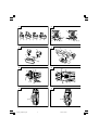 2
2
-
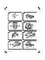 3
3
-
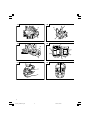 4
4
-
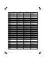 5
5
-
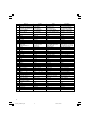 6
6
-
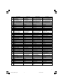 7
7
-
 8
8
-
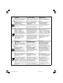 9
9
-
 10
10
-
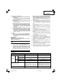 11
11
-
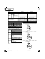 12
12
-
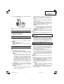 13
13
-
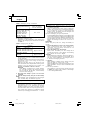 14
14
-
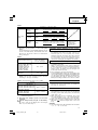 15
15
-
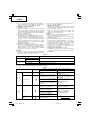 16
16
-
 17
17
-
 18
18
-
 19
19
-
 20
20
-
 21
21
-
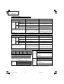 22
22
-
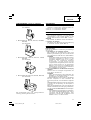 23
23
-
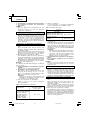 24
24
-
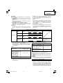 25
25
-
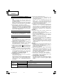 26
26
-
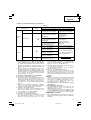 27
27
-
 28
28
-
 29
29
-
 30
30
-
 31
31
-
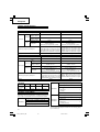 32
32
-
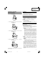 33
33
-
 34
34
-
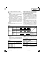 35
35
-
 36
36
-
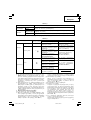 37
37
-
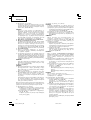 38
38
-
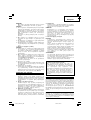 39
39
-
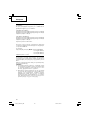 40
40
-
 41
41
-
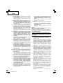 42
42
-
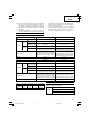 43
43
-
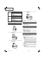 44
44
-
 45
45
-
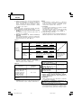 46
46
-
 47
47
-
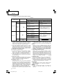 48
48
-
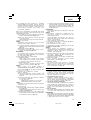 49
49
-
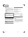 50
50
-
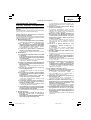 51
51
-
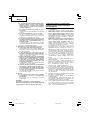 52
52
-
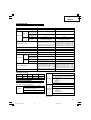 53
53
-
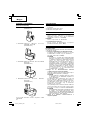 54
54
-
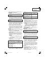 55
55
-
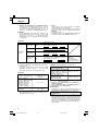 56
56
-
 57
57
-
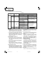 58
58
-
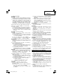 59
59
-
 60
60
-
 61
61
-
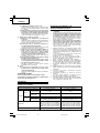 62
62
-
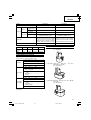 63
63
-
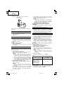 64
64
-
 65
65
-
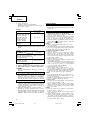 66
66
-
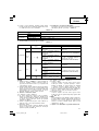 67
67
-
 68
68
-
 69
69
-
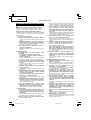 70
70
-
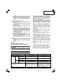 71
71
-
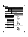 72
72
-
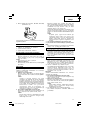 73
73
-
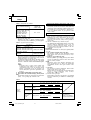 74
74
-
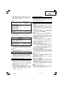 75
75
-
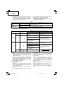 76
76
-
 77
77
-
 78
78
-
 79
79
-
 80
80
-
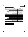 81
81
-
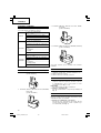 82
82
-
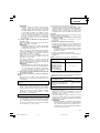 83
83
-
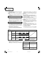 84
84
-
 85
85
-
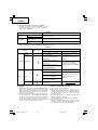 86
86
-
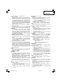 87
87
-
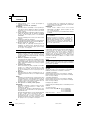 88
88
-
 89
89
-
 90
90
-
 91
91
-
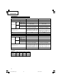 92
92
-
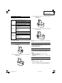 93
93
-
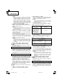 94
94
-
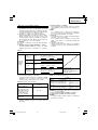 95
95
-
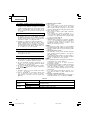 96
96
-
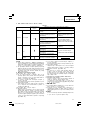 97
97
-
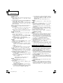 98
98
-
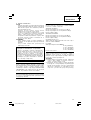 99
99
-
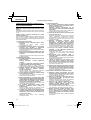 100
100
-
 101
101
-
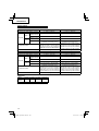 102
102
-
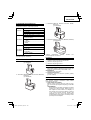 103
103
-
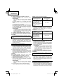 104
104
-
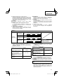 105
105
-
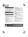 106
106
-
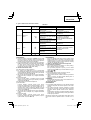 107
107
-
 108
108
-
 109
109
-
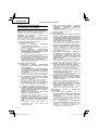 110
110
-
 111
111
-
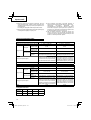 112
112
-
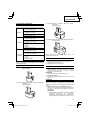 113
113
-
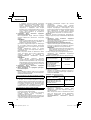 114
114
-
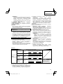 115
115
-
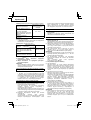 116
116
-
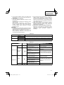 117
117
-
 118
118
-
 119
119
-
 120
120
-
 121
121
-
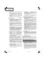 122
122
-
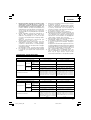 123
123
-
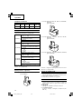 124
124
-
 125
125
-
 126
126
-
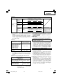 127
127
-
 128
128
-
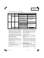 129
129
-
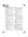 130
130
-
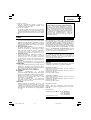 131
131
-
 132
132
-
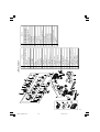 133
133
-
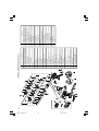 134
134
-
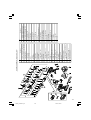 135
135
-
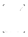 136
136
-
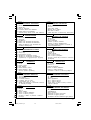 137
137
-
 138
138
-
 139
139
-
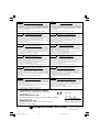 140
140


Hitachi DS 12DVF3 Handling Instructions Manual
- Kategori
- Elektrikli aletler
- Tip
- Handling Instructions Manual
diğer dillerde
- slovenčina: Hitachi DS 12DVF3
- polski: Hitachi DS 12DVF3
- română: Hitachi DS 12DVF3
İlgili makaleler
-
Hitachi DS14DVF3 Handling Instructions Manual
-
Hikoki DS12DVF3 Kullanım kılavuzu
-
Hitachi DS 14DFL Handling Instructions Manual
-
Hikoki DS9DVF2 Kullanım kılavuzu
-
-
Hikoki WH12DAF2 Kullanım kılavuzu
-
Hikoki DV 14DBL Kullanım kılavuzu
-
-
Hikoki DV14DCL2 Kullanım kılavuzu
-