Beko CWB 6441 Kullanım kılavuzu
- Kategori
- Ocak davlumbazları
- Tip
- Kullanım kılavuzu
Bu kılavuz aynı zamanda aşağıdakiler için de uygundur:

Instructions Manual
Bedienungsanleitung
Manuel d’Instructions
Руководство по эксплуатации
Kullanim Kilavuku
Naudojimosi instrukcija
Gebruiksaanwijzing
Brugsvejledning
Εγχειρίδιο οδηγιών
Manual de Instruções
Instrukcja Obslugi
Libret de Instrucţiuni
CWB 6441 – CWB 9441

EN
2
2
Instructions Manual
INDEX
WARNINGS - COMPONENTS.............................................................................................................................................14
INSTALLATION....................................................................................................................................................................15
USE - MAINTENANCE.........................................................................................................................................................16

DE
3
3
Bedienungsanleitung
INHALTSVERZEICHNIS
HINWEIS - KOMPONENTEN...............................................................................................................................................17
MONTAGE............................................................................................................................................................................18
BEDIENUNG - WARTUNG..................................................................................................................................................19

FR
4
4
Manuel d’Instructions
SOMMAIRE
ATTENTION - COMPOSANTS.............................................................................................................................................20
INSTALLATION....................................................................................................................................................................21
UTILISATION - ENTRETIEN................................................................................................................................................22

RU
5
5
Руководство по эксплуатации
УКАЗАТЕЛЬ
ПРАВИЛА ТЕХНИКИ БЕЗОПАСНОСТИ - ПРИНАДЛЕЖНОСТИ....................................................................................23
УСТАНОВКА ........................................................................................................................................................................24
КСПЛУАТАЦИЯ - ТЕХНИЧЕСКОЕ ОБСЛУЖИВАНИЕ.....................................................................................................25

TR
6
6
Kullanim Kilavuku
IÇERIKLER
UYARILAR - PARÇALARI....................................................................................................................................................26
MONTAJ...............................................................................................................................................................................27
KULLANIM - BAKIMI VE TEMİZLENMESİ...........................................................................................................................28

LT
7
7
Naudojimosi instrukcija
TURINYS
ĮSPĖJIMAI - DALYS..............................................................................................................................................................29
MONTAVIMAS......................................................................................................................................................................30
NAUDOJIMAS - VALYMAS IR PRIEŽIŪRA.........................................................................................................................31

NL
8
8
Gebruiksaanwijzing
INHOUDSOPGAVE
AANWIJZINGEN - ONDERDELEN......................................................................................................................................32
INSTALLATIE .......................................................................................................................................................................33
GEBRUIK - ONDERHOUD...................................................................................................................................................34

DK
9
9
Brugsvejledning
INDHOLD
VIGTIGE ANVISNINGER - KOMPONENTER......................................................................................................................35
INSTALLATION....................................................................................................................................................................36
BRUG - VEDLIGEHOLDELSE.............................................................................................................................................37

GR
1
0
10
Εγχειρίδιο οδηγιών
ΠΕΡΙΕΧΟΜΕΝΑ
ΠΡΟΕΙΔΟΠΟΙΗΣΕΙΣ - ΕΞΑΡΤΗΜΑΤΑ.................................................................................................................................38
ΕΓΚΑΤΑΣΤΑΣΗ.....................................................................................................................................................................39
ΧΡΗΣΗ - ΣΥΝΤΗΡΗΣΗ.........................................................................................................................................................40

PT
1
1
11
Manual de Instruções
ÍNDICE
ADVERTÊNCIAS - COMPONENTES..................................................................................................................................41
INSTALAÇÃO.......................................................................................................................................................................42
UTILIZAÇÃO - MANUTENÇÃO............................................................................................................................................43

PL
1
2
12
Instrukcja Obslugi
SPIS TREŚCI
OSTRZEŻENIA - CZĘŚCI SKŁADOWE...............................................................................................................................44
MONTAŻ...............................................................................................................................................................................45
UŻYTKOWANIE – KONSERWACJA...................................................................................................................................46

RO
1
3
13
Libret de Instrucţiuni
CUPRINS
ATENŢIE! - CONŢINE........................................................................................................................................................47
INSTALAREA........................................................................................................................................................................48
UTILIZARE - INTRETINERE................................................................................................................................................49

EN
1
4
14
WARNINGS - COMPONENTS
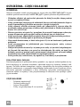
WARNINGS
This appliance has been designed for use as either an EXTRACTION (ducting to the outside)
or RECIRCULATION (filtering) hood. The measurements contained on the drawings in this
booklet refer to two models of cooker hood. Therefore, it is essential that you refer to the cor-
rect drawing when taking measurements for installation.
- The minimum distance between the cooking surface and the metal grease filters on the
underside of the hood must be 650mm.
- This cooker hood must be installed in accordance with the installation instructions and
all requirements must be adhered to.
- If the room where the cooker hood is to be used contains a fuel burning appliance such
as a central heating boiler then its flue must be of the room sealed or balance flue type.
- If other types of flue or appliances are fitted ensure that there is an adequate supply of
air to the room.
- When the range hood and appliance supplied with energy other than electricity are
simultaneously in operation, the negative pressure in the room must not exceed 4 Pa
(4x10
-5
bar).
- The ducting system for this appliance must not be connected to any ventilation system
which is being used for any other purpose.
- The ducting system for this appliance must not be connected to any existing ventilation
system which is being used for any other purpose.
- Do not leave naked flames or carry out flambè cooking under this cooker hood.
- This appliance is not intended for use by persons (including children) with reduced
physical, sensory or mental capabilities, or lack of experience and knowledge, unless
they have been given supervision or instruction concerning use of the appliance by a
person responsible for their safety.
- Children should be supervised to ensure that they do not play with the appliance
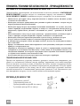
CONNECTING THE POWER CABLE TO THE MAINS POWER SUPPLY
Before installation, check that the mains voltage indicated on the rating plate inside the appli-
ance corresponds to the voltage available in your home. If the Hood is not fitted with a plug, fit
the power cable with a plug of a type approved for the load indicated on the rating plate; when
connecting directly to the mains, insert an omnipolar circuit breaker with a minimum contact
aperture of 3mm and a size suitable for the load in question between the appliance and the
mains supply, making sure it is of a type that complies with current regulations.
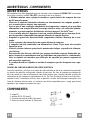
COMPONENTS
- 2 No Wall Brackets C
- 1 No 150-120mm Ducting Spigot G
- 1 No Air Outlet Connection H (Optional)
- 2 No Charcoal Filters L (Optional)

EN
1
5
15
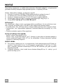
INSTALLATION
The cooker hood must be installed centrally over a cooking appliance. The minimum distance
between the cooking surface and the metal grease filters on the underside of the hood must be
at least 650mm.
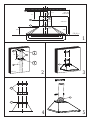
To install the hood proceed as follows:
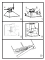
1) Drill six 8mm diameter holes at X1-X2-J and insert the plastic rawl plugs supplied as illus-
trated in fig. 2 ensuring the brackets are fitted as shown in the blow up.
2) Secure the two brackets C to the wall inserting two of the screws supplied through the two
holes on line X1-X2 as illustrated in fig. 2.
3) Slide the canopy down the wall to locate the key hole over the washer then secure the can-
opy to the wall by inserting two of the screws supplied through the two outer holes in the
rim of the canopy J1 and J2 as illustrated in fig. 3.
4) EXTRACTION OR RECIRCULATION INSTALLATION:
• EXTRACTION (DUCTED)
When installing the ducted version, connect the hood to the chimney using either a flexible or
rigid pipe ø 150 or 120 mm, the choice of which is left to the installer.
• To install a ø 120 mm air exhaust connection, insert the reducer flange 9 on the hood body
outlet.
• Fix the pipe in position using sufficient pipe clamps (not supplied).
• Remove any activated charcoal filters.
• RECIRCULATION (FILTERED)
• When the hood is fitted in the recirculation mode the Air Outlet Connection H should be
fitted as illustrated in fig. 6.
• Fit the (optional) charcoal filters by repeating the following operation on each side of the
motor housing. Place the two key hole slots in the filter L and turn the filter clockwise to
lock the filter in position as illustrated in fig. 7.
WARNING: It is a possible fire hazard if the metal grease filters are not cleaned and the
charcoal filters replaced regularly.
Fitting The Chimney
5) FITTING THE CHIMNEY UPPER
To fit the upper chimney A, place the top edge of the chimney over the bracket C as illus-
trated in fig. 8 and secure the chimney using two of the 2.9mm self tapping screws pro-
vided.
The distance H in the height between the fixing holes X1 and X2 is determined by the
height of the upper chimney A.
6) FITTING THE CHIMNEY LOWER
To fit the lower chimney B, apply slight force to the two rear edges to increase the width
of the apperture, then sleeve the chimney B over the chimney A as illustrated in fig. 9.

EN
1
6
16
USE - MAINTENANCE
USE
The cooker hood functions are controlled by a series of slider or push button switches mounted
on the front of the hood and control the worktop lighting and fan motor speeds. This cooker
hood will not remove steam.
1) SLIDER SWITCHES
- A switch controls the wotktop lighting - ON/OFF.
- A switch controls the fan speeds - OFF/ON-1-2-3.
- The red neon lamp illuminates when the motor is switched ON .
2) PUSH BUTTON SWITCHES
- A switch controls the worktop lighting - ON/OFF.
- A button switches the motor OFF/ON at the low speed setting.
- A button switches the motor to the medium speed setting.
- A button switches the motor to the high speed setting.
- The red neon lamp illuminates when the motor is switched ON.
3) SPEED SETTINGS
- 1/Low should be selected when simmering or when using only one pan.
- 2/Medium should be selected for cooking when using up to four pans.
- 3/High should be selected when frying or cooking food with a strong odour.
MAINTENANCE
N.B. Before carring out any kind of maintenance, cleaning or replacing lamps, disconnect the
hood from the mains supply.
1. Lighting
Comprises two 40W bulbs. To replace the bulbs, proceed as follows (fig.10): Remove one
of the pins at the sides of the lamp cover. Slide the glass towards the side from which the
pin has been removed until the opposite edge has been freed, then pull gently downwards.
Replace the bults and fit the glass again by repeating the above operations in reverse order.
2. Filters
- The metal grease filter should be cleaned every two months or more frequently if the hood
is used consistently and can be cleaned in a dishwasher or by hand using a mild detergent
or liquid soap. When replacing, ensure that they are dry.
- The charcoal filter cannot be washed and should be replaced at least every 2 months or
more frequently if the hood is used consistently.
3. Cleaning
When cleaning the hood, it is recommended to use a damp cloth and mild liquid household
cleaner. Never use abrasive cleaning materials.
IMPORTANT: When using a gas hob in connection with the cooker hood never leave the
burners of the hob uncovered while the hood is in use or when the pans have been re-
moved. It is very important to follow all instructions for cleaning the hood and filters.
There could be a possible fire hazard if the filters are not replaced according to these in-
structions.
ATTENTION: The manufacturer declines all responsibility for any damage or injury
caused as a result of not following the instructions for installation, for maintenance and re-
placement times of filters indicated (in order to avoid a possible risk of fire when the filters
are saturated with grease).

DE
1
7
17
HINWEIS - KOMPONENTEN
HINWEISE
Dieses Gerät ist sowohl als ABLUFTHAUBE (Abführung der Luft nach außen), als auch als
UMLUFTHAUBE (Filtrierung der Dünste im Innern) verwendbar.
- Der Mindestabstand zwischen Kochfeld und Unterseite der Haube soll 650 mm betragen.
- Wenn die Luft nach Außen abgeführt wird (Abluftbetrieb), muss die Haube nach den folgenden An-
weisungen installiert werden.
- Bei gleichzeitigem Betrieb der Dunstabzugshaube im Abluftbetrieb und Feuerstätten darf im Auf-
stellraum der Feuerstätte der Unterdruck nicht größer als 4 Pa (4x10
-5
bar) sein.
- Das Abluftrohr der Haube darf keinesfalls an den Rauchabzug von Feuerstätten angeschlossen wer-
den.
- Die Abluftvorschriften der zuständigen Behörden beachten.
- Niemals eine Flamme unter der Dunsthaube unbedeckt lassen.
- Das Gerät entspricht der Schutzklasse II und muss daher nicht geerdet werden.
- Vor Wartungsarbeiten muss das Gerät spannungslos gemacht werden.
- Dieses Gerät darf nicht von Personen, auch Kindern, mit verminderten psychischen, sensorischen
und geistigern Fähigkeiten, oder von Personen ohne Erfahrung und Kenntnisse benutzt werden, so-
fern sie nicht von für ihre Sicherheit verantwortlichen Personen beaufsichtigt und beim Gebrauch
des Geräts angeleitet werden.
- Kinder dürfen sich nicht unbeaufsichtigt in der Nähe des Geräts aufhalten und auf keinen Fall mit
dem Gerät spielen.
ANSCHLUSS DES STROMKABELS AN DAS NETZ
Vor der Installation muss kontrolliert werden, ob die am Typenschild im Geräteinnern angege-
bene Netzspannung der Spannung Ihres Haushalts entspricht. Falls das Gerät ohne Stecker ist,
muss das Kabel mit einem genormten, für die am Typenschild angegebene Last ausreichenden
Stecker versehen werden; bei direktem Anschluss an das Netz muss ein korrekt dimensionier-
ter allpoliger Schalter mit einer Mindestkontaktöffnung von 3 mm zwischengeschaltet werden,
der den einschlägigen Vorschriften entspricht.
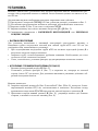
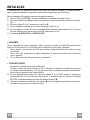
KOMPONENTEN
- 2 Wandhalterungen C
- 1 Reduzierflansch G
- 1 Filterstutzen H (Option)
- 2 Aktivkohlefilter L (Option)

DE
1
8
18
MONTAGE
Die Haube muss mittig über dem Kochfeld installiert werden. Der Mindestabstand zwischen
Kochfeld und Unterseite der Haube soll 650 mm betragen.
Für die Installation wie folgt vorgehen:
1) 6 Löcher (X1-X2-J) mit 8 mm Durchmesser nach den Maßangaben der Abb.1 ausführen.
2) Die für die jeweilige Montage mitgelieferten Schrauben und Dübel verwenden.
3) Die Wandhalterungen C (Abb. 2) mittels der Bohrungen X1-X2 an der Wand befestigen.
4) Die Haube mittels der externen Bohrlöcher J1 und J2 (Abb. 3) an der Wand befestigen.
5) Montage als ABLUFTHAUBE oder UMLUFTHAUBE:
ABLUFTBETRIEB
Bei Abluftbetrieb kann die Haube vom Installateur wahlweise mittels Rohr oder Schlauch (ø
150 oder 120 mm) an den Auslass angeschlossen werden.
- Bei Verwendung eines Anschlussrohres ø 120 den Reduzierflansch 9 am Haubenausgang
anbringen.
- Das Rohr mit passenden Rohrschellen fixieren. Das hierzu erforderliche Material wird
nicht mitgeliefert.
- Eventuell vorhandene Aktivkohlefilter ausbauen.
UMLUFTBETRIEB (OPTION)
- Den Filterstutzen H einbauen (Abb. 6).
- Den Aktivkohlefilter L (Abb.7) einlegen und durch Drehen im Uhrzeigersinn (um zirka
10°) einrasten lassen. Zum Ausbauen in umgekehrter Reihenfolge vorgehen.
Montage der Kamine:
6) Befestigen Sie das obere Kaminteil A (Abb. 8) mit den vier beiliegenden, selbstschneiden-
den Schrauben Ø 2,9 mm an den Halterungen C (Abb.2/Abb.8). Der Abstand zwischen
den Bohrlöchern X1 und X2 hängt von der Höhe des oberen Kaminteils H ab.
7) Um das untere Kaminteil B (Abb. 9) anzubringen die beiden Seitenteile leicht auseinan-
derbiegen und dann an der Haube einsetzen (Abb. 9).

DE
1
9
19
BEDIENUNG - WARTUNG
BEDIENUNG
Die Dunsthaube ist, je nach Modellart, mit verschiedenen Schiebeschaltern oder Drucktasten
an der Haubenfront ausgestattet, mit denen die Arbeitsflächenbeleuchtung und die Motorge-
schwindigkeit geschaltet werden .
1) Schiebeschaltung
Ein Schalter schaltet die Beleuchtung ein.
Ein Schalter steuert die drei Gebläsestufen.
Eine Kontrolllampe zeigt den Motorbetrieb an.
2) Drucktastenschaltung
Ein Schalter schaltet die Beleuchtung ein
Ein Schalter schaltet den Motor ein und aus ( niedrigste Stufe).
Ein Schalter schaltet die mittlere Stufe ein.
Ein Schalter schaltet die höchste Stufe ein.
Die rote Kontrolllampe zeigt an, wenn der Motor eingeschaltet ist.
3) Geschwindigkeitsstufen
1 / niedrig bei Benutzung einer Kochplatte
2 / mittel beim Gebrauch bis zu vier Kochplatten
3 / hoch beim Braten oder bei starkem Kochdunst
WARTUNG
N.B. Vor sämtlichen Wartungs- und Reparaturarbeiten bzw. vor Auswechseln der Lampen
muss die Stromzufuhr zum Gerät unterbrochen werden.
1. Beleuchtung
Die Beleuchtung besteht aus zwei Lampen zu 40W. Beim Austausch einer Lampe ist wie
folgt vorzugehen (Abb.10): einen der Stifte an der Lampenabdeckungsseite entfernen.
Dann das Glas auf die Seite ohne Stift schieben, bis das gegenüberliegende Ende frei liegt
und etwas senken. Die Lampen austauschen und die Glasabdeckung in umgekehrter Rei-
henfolge wieder montieren.
2. Filter
Je nach Einsatzhäufigkeit müssen die Metallfettfilter in angebrachten Zeitabständen (ma-
ximal alle 2 Monate) demontiert und mit warmem Seifenwasser bzw. im Geschirrspüler
gereinigt und trocken wieder montiert werden (Aktivkohlefilter dürfen keinesfalls gewa-
schen werden, sondern sind alle 2 Monate auszuwechseln).
3. Pflege
Zur Außenreinigung der Haube ein mit Alkohol oder zweckentsprechenden, handelsübli-
chen Reinigungsmitteln angefeuchtetes Tuch verwenden. Scheuermittel sind zu vermei-
den.
WICHTIG: Offene Flammen schädigen die Filter; deshalb wird davon abgeraten, Gaskoch-
stellen ohne Kochtopf brennen zu lassen. Die Maßnahmen zur Reinigung der Haube bzw. der
Filter und das Auswechseln der Filter haben verbindlich gemäß unseren Vorschriften und in
regelmäßigen Zeitabständen zu erfolgen, um Brandgefahr zu vermeiden.
ACHTUNG: Die Herstellerfirma übernimmt keine Haftung für Schäden, die durch unterlas-
sene Wartung des Fettfilters (alle zwei Monate auswaschen), unterlassenes Auswechseln des
Aktivkohlefilters und Nichtbeachtung der obengenannten Anleitungen zur Montage und zum
Elektronanschluss entstehen.

FR
2
0
20
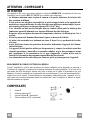
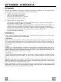
ATTENTION - COMPOSANTS
ATTENTION
Cet appareil a été conçu pour être employé en version ASPIRANTE (évacuation de l'air vers
l'extérieur) ou en version RECYCLAGE (air conduite vers l'intérieur).
- La distance minimum entre le plan de cuisson et la partie inférieure de la hotte doit
être au moins de 650mm.
- Il faut prévoir une aération convenable de la pièce lorsque la hotte et les appareils ali-
mentés avec énergie différente de celle éléctrique sont utilisés en même temps; la pres-
sion négative de la pièce ne doit pas dépasser 4Pa (4x10
-5
bar).
- L'air recueillie ne doit pas être dirigée dans un conduit utilisé pour la décharge des
fumées des appareils alimentés avec énergie différente de celle éléctrique.
- Respecter les prescriptions des autorités compétentes relatives à la décharge de l'air à
evacuer.
- Eviter la présence de flammes libres dans l'espace au dessous de la hotte.
- La hotte a été construite avec isolement en classe II, donc il n'y a pas besoin de la relier
à la terre.
- Avant d'effectuer toutes les opérations d'entretien, débrancher l'appareil de l'alimen-
tation éléctrique.
- Cet appareil ne doit pas être utilisé par des personnes (y compris les enfants) ayant des
capacités psychiques, sensorielles ou mentales réduites, ni par des personnes n’ayant
pas l’expérience et la connaissance de ce type d’appareils, à moins d'être sous le
contrôle et la formation de personnes responsables de leur sécurité.
- Les enfants doivent être surveillés pour s'assurer qu'ils ne jouent pas avec l'appareil.
BRANCHEMENT DU CÂBLE ÉLECTRIQUE AU RÉSEAU
Avant l’installation, vérifier que la tension du réseau indiquée sur la plaquette se trouvant à
l’intérieur de l’appareil correspond à la tension électrique de votre habitation. Si la hotte n’est
pas munie de fiche électrique, monter une fiche à norme sur le câble d’alimentation qui soit
adaptée à la tension indiquée sur la plaquette des caractéristiques. En cas de branchement élec-
trique direct sur le réseau, il faudra placer un interrupteur omnipolaire entre l’appareil et le ré-
seau ayant une ouverture minimum entre les contacts de 3 mm, et adapté à la tension et répon-
dant aux normes en vigueur.
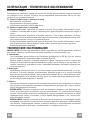
COMPOSANTS
- 2 brides C
- 1 bride de réduction G
- 1 raccord filtrant H (optionnel)
- 2 filtres charbon actif L (optionnel)
Sayfa yükleniyor...
Sayfa yükleniyor...
Sayfa yükleniyor...
Sayfa yükleniyor...
Sayfa yükleniyor...
Sayfa yükleniyor...
Sayfa yükleniyor...
Sayfa yükleniyor...
Sayfa yükleniyor...
Sayfa yükleniyor...
Sayfa yükleniyor...
Sayfa yükleniyor...
Sayfa yükleniyor...
Sayfa yükleniyor...
Sayfa yükleniyor...
Sayfa yükleniyor...
Sayfa yükleniyor...
Sayfa yükleniyor...
Sayfa yükleniyor...
Sayfa yükleniyor...
Sayfa yükleniyor...
Sayfa yükleniyor...
Sayfa yükleniyor...
Sayfa yükleniyor...
Sayfa yükleniyor...
Sayfa yükleniyor...
Sayfa yükleniyor...
Sayfa yükleniyor...
Sayfa yükleniyor...
Sayfa yükleniyor...
Sayfa yükleniyor...
Sayfa yükleniyor...
-
 1
1
-
 2
2
-
 3
3
-
 4
4
-
 5
5
-
 6
6
-
 7
7
-
 8
8
-
 9
9
-
 10
10
-
 11
11
-
 12
12
-
 13
13
-
 14
14
-
 15
15
-
 16
16
-
 17
17
-
 18
18
-
 19
19
-
 20
20
-
 21
21
-
 22
22
-
 23
23
-
 24
24
-
 25
25
-
 26
26
-
 27
27
-
 28
28
-
 29
29
-
 30
30
-
 31
31
-
 32
32
-
 33
33
-
 34
34
-
 35
35
-
 36
36
-
 37
37
-
 38
38
-
 39
39
-
 40
40
-
 41
41
-
 42
42
-
 43
43
-
 44
44
-
 45
45
-
 46
46
-
 47
47
-
 48
48
-
 49
49
-
 50
50
-
 51
51
-
 52
52


Beko CWB 6441 Kullanım kılavuzu
- Kategori
- Ocak davlumbazları
- Tip
- Kullanım kılavuzu
- Bu kılavuz aynı zamanda aşağıdakiler için de uygundur:
diğer dillerde
- français: Beko CWB 6441 Manuel utilisateur
- dansk: Beko CWB 6441 Brugermanual
- română: Beko CWB 6441 Manual de utilizare
Diğer belgeler
-
Zanussi ZHC6141X Kullanım kılavuzu
-
-
Electrolux EFC60110X Kullanım kılavuzu
-
ELICA STONE IX/A/33 Yükleme Rehberi
-
Smeg KSEV-910 X1 El kitabı
-
Faber VALIA El kitabı
-
V-ZUG 042 Kullanma talimatları
-
 Franke Consumer Products FBI 722 Kullanım kılavuzu
-
-
