Dell N20XX Kullanım kılavuzu
- Kategori
- Ağ anahtarları
- Tip
- Kullanım kılavuzu
Bu kılavuz aynı zamanda aşağıdakiler için de uygundur:

Dell N20xx/N30xx
Series Switch
Getting Started Guide
Guide de mise en route
Handbuch zum Einstieg
Руководство по началу работы
Guía de introducción
Başlangıç Kılavuzu
הדובע תליחת ךירדמ
Regulatory Models: N2024, N2024P,
N2048, N2048P, N3024, N3024P, N3048,
N3048P, N3024F


Dell N20xx/N30xx
Series Switch
Getting Started Guide
Regulatory Models: N2024, N2024P,
N2048, N2048P, N3024, N3024P, N3048,
N3048P, N3024F

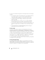
Notes, Cautions, and Warnings
NOTE: A NOTE indicates important information that helps you make better use of
your switch.
CAUTION: A CAUTION indicates either potential damage to hardware or loss of
data and tells you how to avoid the problem.
WARNING: A WARNING indicates a potential for property damage, personal
injury, or death.
____________________
© 2013 Dell Inc.
Trademarks used in this text: Dell
®
, the DELL logo, OpenManage™, and ReadyRails™ are
trademarks of Dell Inc. Microsoft
®
, and Windows
®
are registered trademarks of Microsoft Corporation
in the United States and/or other countries.
Regulatory Models N2024, N2024P, N2048, N2048P, N3024, N3024P, N3048, N3048P, N3024F
December 2013 P/N F5CWH Rev. A00

Contents 3
Contents
1 Introduction . . . . . . . . . . . . . . . . . . . . . . . . 7
2 N20xx Series Overview
. . . . . . . . . . . . . . . 7
3 N20xx Series Hardware Overview
. . . . . . . 8
N20xx Series Front Panel . . . . . . . . . . . . . . . . . 8
Switch Ports
. . . . . . . . . . . . . . . . . . . . 10
Console Port
. . . . . . . . . . . . . . . . . . . . 10
USB Port
. . . . . . . . . . . . . . . . . . . . . . 11
Reset Button
. . . . . . . . . . . . . . . . . . . . 11
Port and System LEDs
. . . . . . . . . . . . . . . 11
Stack Master LED and Stack Number Display
. . . 11
N20xx Series Back Panel
. . . . . . . . . . . . . . . . 12
Power Supplies
. . . . . . . . . . . . . . . . . . . 12
Ventilation System
. . . . . . . . . . . . . . . . . 13
N20xx Model Summary
. . . . . . . . . . . . . . . . . 13
4 N20xx Series Installation . . . . . . . . . . . . 14
Site Preparation . . . . . . . . . . . . . . . . . . . . . 14
Unpacking the N20xx Switch
. . . . . . . . . . . . . . 15
Package Contents
. . . . . . . . . . . . . . . . . 15
Unpacking Steps
. . . . . . . . . . . . . . . . . . 15

4 Contents
Rack Mounting a N20xx Switch . . . . . . . . . . . . . 15
Installing in a Rack
. . . . . . . . . . . . . . . . . 15
Installing as a Free-standing Switch
. . . . . . . . 17
Stacking Multiple N20xx Switches
. . . . . . . . . . . 17
Creating a Switch Stack
. . . . . . . . . . . . . . 17
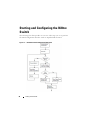
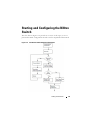
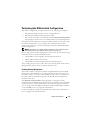
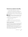
5 Starting and Configuring the N20xx Switch 20
Connecting a N20xx Switch to a Terminal . . . . . . . 21
Connecting a N20xx Switch to a Power Source
. . . . 22
AC and DC Power Connection
. . . . . . . . . . . 22
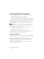
Booting the N20xx Switch
. . . . . . . . . . . . . . . . 23
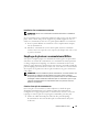
Performing the N20xx Initial Configuration
. . . . . . . 24
Enabling Remote Management
. . . . . . . . . . . 24
Initial Configuration Procedure
. . . . . . . . . . . 25
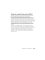
Example Session
. . . . . . . . . . . . . . . . . . 26
Dell Easy Setup Wizard Console Example
. . . . . 27
Next Steps
. . . . . . . . . . . . . . . . . . . . . 30
6 N30xx Series Overview . . . . . . . . . . . . . 31
7 N30xx Series Hardware Overview
. . . . . 31
N30xx Series Front Panel . . . . . . . . . . . . . . . . 32
Switch Ports
. . . . . . . . . . . . . . . . . . . . 34
Console Port
. . . . . . . . . . . . . . . . . . . . 34
Out-of-Band Management Port
. . . . . . . . . . . 35
USB Port
. . . . . . . . . . . . . . . . . . . . . . 35
Reset Button
. . . . . . . . . . . . . . . . . . . . 35

Contents 5
Port and System LEDs . . . . . . . . . . . . . . . 35
Stack Master LED and Stack Number Display
. . . 36
N30xx Series Back Panel
. . . . . . . . . . . . . . . . 36
Expansion Slots for Plug-in Modules
. . . . . . . . 37
Power Supplies
. . . . . . . . . . . . . . . . . . . 38
Ventilation System
. . . . . . . . . . . . . . . . . 38
N30xx Model Summary
. . . . . . . . . . . . . . . . . 39
8 N30xx Series Installation . . . . . . . . . . . . 40
Site Preparation . . . . . . . . . . . . . . . . . . . . . 40
Unpacking the N30xx Switch
. . . . . . . . . . . . . . 41
Package Contents
. . . . . . . . . . . . . . . . . 41
Unpacking Steps
. . . . . . . . . . . . . . . . . . 41
Rack Mounting a N30xx Switch
. . . . . . . . . . . . . 42
Rack Mounting Safety Considerations
. . . . . . . 42
Installing the Dell ReadyRail System
. . . . . . . . 43
Installing as a Free-standing Switch
. . . . . . . . 47
Stacking Multiple N30xx Switches
. . . . . . . . . . . 47
Creating a Switch Stack
. . . . . . . . . . . . . . 47
9 Starting and Configuring the N30xx Switch 49
Connecting a N30xx Switch to a Terminal . . . . . . . 50
Connecting a N30xx Switch to a Power Source
. . . . 51
AC and DC Power Connection
. . . . . . . . . . . 51
Booting the N30xx Switch
. . . . . . . . . . . . . . . . 52
Performing the N30xx Initial Configuration . . . . . . . 53


Getting Started Guide 7
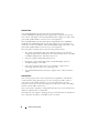
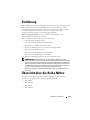
Introduction
This document provides basic information about the Dell N20xx/N30xx
Series switches, including how to install a switch and perform the initial
configuration. For information about how to configure and monitor switch
features, see the User’s Configuration Guide, which is available on the Dell
Support website at dell.com/support/manuals, for the latest updates on
documentation and firmware.
This document contains the following sections:
• N20xx Series Overview
• N20xx Series Hardware Overview
• N20xx Series Installation
• Starting and Configuring the N20xx Switch
• N30xx Series Overview
• N30xx Series Hardware Overview
• N30xx Series Installation
• Starting and Configuring the N30xx Switch
NOTE: Switch administrators are strongly advised to maintain Dell Networking
switches on the latest version of the Dell Networking Operating System (DNOS).
Dell Networking continually improves the features and functions of DNOS based on
feedback from you, the customer. For critical infrastructure, prestaging of the new
release into a noncritical portion of the network is recommended to verify network
configuration and operation with the new DNOS version.
N20xx Series Overview
The Dell N20xx switches are stackable Layer 2 Gigabit Ethernet switches and
include the following models:
• Dell N2024
• Dell N2024P
• Dell N2048
• Dell N2048P

8 Getting Started Guide
N20xx Series Hardware Overview
This section contains information about device characteristics and modular
hardware configurations for the N20xx Series switches.
All N20xx non-PoE models are 1U, rack-mountable switches with the
following physical dimensions:
• 440.0 x 257.0 x 43.5 mm (W x D x H).
• 17.3 x 10.1 x 1.7 inches (W x D x H).
All N20xx PoE models are 1U, rack-mountable switches with the following
physical dimensions:
• 440.0 x 387.0 x 43.5 mm (W x D x H).
• 17.3 x 15.2 x 1.7 inches (W x D x H).
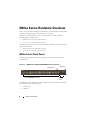
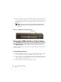
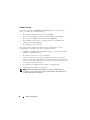
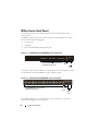
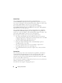
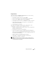
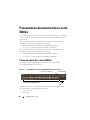
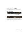
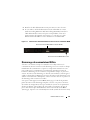
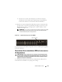
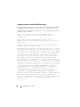
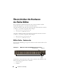
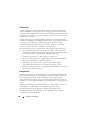
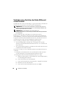
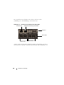
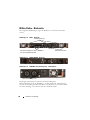
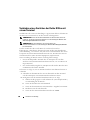
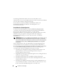
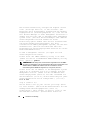
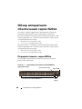
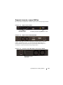
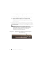
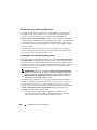
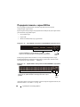
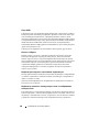
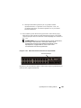
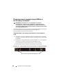
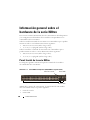
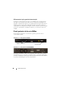
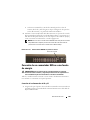
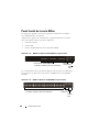
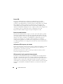
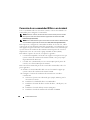
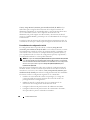
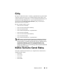
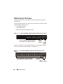
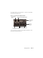
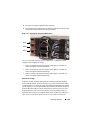
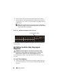
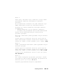
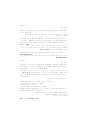
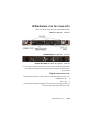
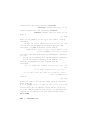
N20xx Series Front Panel
The following images show the front panels of the switch models in the
N20xx Series.
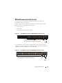
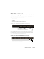
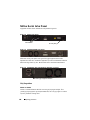
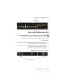
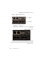
Figure 1-1. N2048 Series with 48 10/100/1000BASE-T Ports (Front Panel)
In addition to the switch ports, the front panel of each model in the N20xx
series includes the following ports:
• Console port
• USB port
48 10/100/1000BASE-T Ports
SFP+
Ports
Console Port
USB Port

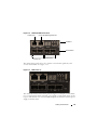
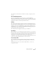
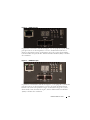
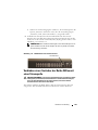
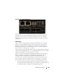
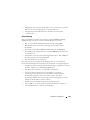
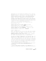
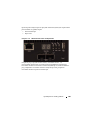
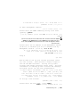
Getting Started Guide 9
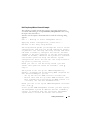
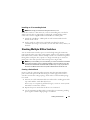
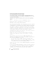
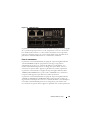
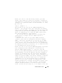
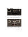
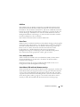
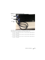
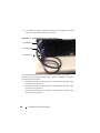
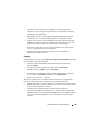
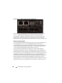
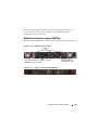
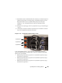
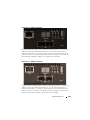
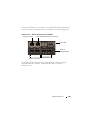
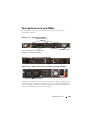
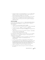
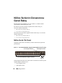
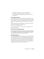
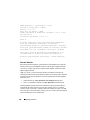
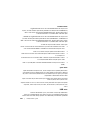
Figure 1-2. N2024 Close-up
The N20xx front panel, shown in Figure 1-2, has status LEDs for over-
temperature alarm, internal power, and status on the top row. The bottom
row of status LEDs displays stack master, redundant power supply (RPS)
status and fan alarm status.
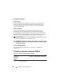
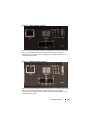
Figure 1-3. N2024P Close-up
The N20xxP front panel, shown in Figure 1-3, has status LEDs for over-
temperature alarm, internal power and status on the top row. The bottom row
of status LEDs displays stack master, modular power supply (MPS) status and
fan alarm status.

10 Getting Started Guide
Switch Ports
The N2024/N2024P front panel provides 24 Gigabit Ethernet
(10/100/1000BASE-T) RJ-45 ports that support auto-negotiation for speed,
flow control, and duplex. The N2024/N2024P models support two SFP+ 10G
ports. Dell-qualified SFP+ transceivers are sold separately.
The N2048/N2048P front panel provides 48 Gigabit Ethernet (10BASE-T,
100BASE-TX, 1000BASE-T) RJ-45 ports that support auto-negotiation for
speed, flow control, and duplex. The N2048/N2048P support two SFP+ 10G
ports. Dell-qualified SFP+ transceivers are sold separately.
The front-panel switch ports have the following characteristics:
• The switch automatically detects the difference between crossed and
straight-through cables on RJ-45 ports and automatically chooses the MDI
or MDIX configuration to match the other end.
• SFP ports support Dell-qualified transceivers.
• RJ-45 ports support full-duplex mode 10/100/1000 Mbps speeds on
standard Category 5 UTP cable.
• SFP+ ports support SFP+ transceivers and SFP+ copper twin-ax
technology plus SFP transceivers operating at 1G.
• The N2024P/N2048P front panel ports support PoE (15.4W) and PoE+
(30W).
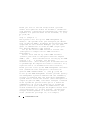
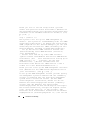
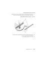
Console Port
The console port provides serial communication capabilities, which allows
communication using RS-232 protocol. The serial port provides a direct
connection to the switch and allows access to the CLI from a console
terminal connected to the port through the provided serial cable (with RJ45
YOST to female DB-9 connectors).
The console port is separately configurable and can be run as an asynchronous
link from 1200 baud to 115,200 baud.
The Dell CLI only supports changing the speed. The defaults are 9600 baud
rate, 8 data bits, No Parity, 1 Stop Bit, No Flow Control.

Getting Started Guide 11
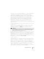
USB Port
The Type-A, female USB port supports a USB 2.0-compliant flash memory
drive. The Dell Networking switch can read or write to a flash drive formatted
as FAT-32. You can use a USB flash drive to copy switch configuration files
and images between the USB flash drive and the switch. You can also use the
USB flash drive to move and copy configuration files and images from one
switch to other switches in the network.
The USB port does not support any other type of USB device.
Reset Button
The reset button is accessed through the pinhole and allows you to perform a
hard reset on the switch. To use the reset button, insert an unbent paper clip
or similar tool into the pinhole. When the switch completes the boot process
after the reset, it resumes operation with the most recently saved
configuration. Any changes made to the running configuration that were not
saved to the startup configuration prior to the reset are lost.
Port and System LEDs
The front panel contains light emitting diodes (LEDs) that indicate the
status of port links, power supplies, fans, stacking, and the overall system
status.
For information about the status that the LEDs indicate, see the User’s
Configuration Guide.
Stack Master LED and Stack Number Display
When a switch within a stack is the master unit, the stack master LED, which
is labeled M, is solid green. If the M LED is off, the stack member is not the
master unit. The Stack No. panel displays the unit number for the stack
member. If a switch is not part of a stack (in other words, it is a stack of one
switch), the M LED is illuminated, and the unit number is displayed.

12 Getting Started Guide
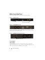
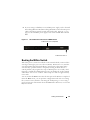
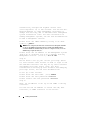
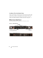
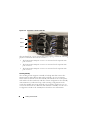
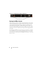
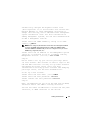
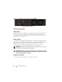
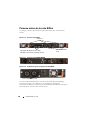
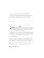
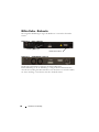
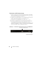
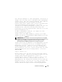
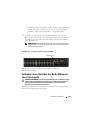
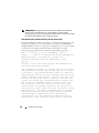
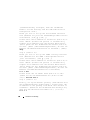
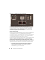
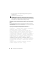
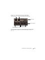
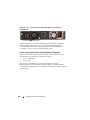
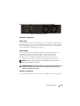
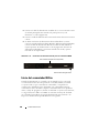
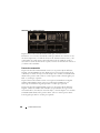
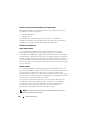
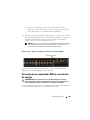
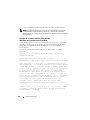
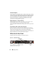
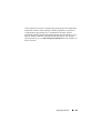
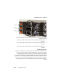
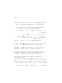
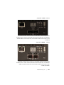
N20xx Series Back Panel
The following images show the back panels of the N20xx switches.
Figure 1-4. N20xx Back Panel
Figure 1-5. N2024P/N2048P Back Panel
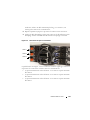
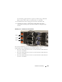
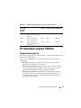
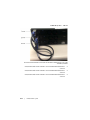
The term mini-SAS refers to the stacking port cable connections shown in
Figure 1-6. See Stacking Multiple N20xx Switches for information on using
the mini-SAS ports to connect switches.
Figure 1-6. N2048 Mini-SAS Stacking Ports and Fans
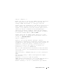
Power Supplies
N2024 and N2048
N2024 and N2048 switches have an internal 100-watt power supply. The
additional redundant power supply (Dell Networking RPS720) provides 180
watts of power and gives full redundancy for the switch.
Fan Vents
AC Power Receptacle
Mini-SAS stacking ports

Getting Started Guide 13
N2024P and N2048P
Dell Networking N2024P and N2048P switches have an internal 1000-watt
power supply feeding up to 24 PoE devices at full PoE+ power (850W). An
additional external power supply (MPS1000) provides 1000 watts and gives
full power coverage for all 48 PoE devices (1800W).
NOTE: PoE power is dynamically allocated. Not all ports will require the full PoE+
power.
CAUTION: Remove the power cable from the power supplies prior to removing
the power supply module itself. Power must not be connected prior to insertion in
the chassis.
Ventilation System
Two fans cool the N20xx switches.
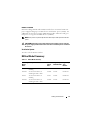
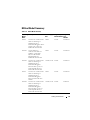
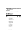
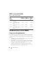
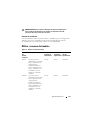
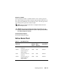
N20xx Model Summary
Table 1-1. N20xx Model Summary
Marketing
Model
Name
Description Power
Supply
Unit
Regulatory
Model Number
Regulatory
Typ e
Number
N2024 24x1G/2x10G SFP+/2x
Stacking
100W E04W E04W001
N2024P 24x1G/2x10G SFP+/2x
Stacking/24x PoE+ Ports
1000W E05W E05W001
N2048 48x1G/2x10G SFP+/2x
Stacking
100W E04W E04W002
N2048P 48x1G/2x10G SFP+/2x
Stacking/48x PoE+ Ports
1000W E05W E05W002

14 Getting Started Guide
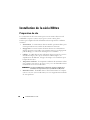
N20xx Series Installation
Site Preparation
N20xx Series switches can be mounted in a standard 48.26 cm (19-inch) rack
or placed on a flat surface.
Make sure that the chosen installation location meets the following site
requirements:
•
Power
— The switch is installed near an easily accessible 100–240 VAC,
50–60 Hz outlet.
•
Clearance
— There is adequate front and rear clearance for operator
access. Allow clearance for cabling, power connections, and ventilation.
•
Cabling
— The cabling is routed to avoid sources of electrical noise such
as radio transmitters, broadcast amplifiers, power lines, and fluorescent
lighting fixtures.
•
Ambient Temperature
— The ambient switch operating temperature
range is 0 to 45ºC (32 to 113ºF) at a relative humidity of up to 95 percent,
non-condensing.
NOTE: Decrease the maximum temperature by 1°C (1.8°F) per 300 m (985 ft.) above
900m (2955 ft.).
•
Relative Humidity
— The operating relative humidity is 8% to 85%
(noncondensing) with a maximum humidity gradation of 10% per hour.

Getting Started Guide 15
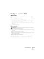
Unpacking the N20xx Switch
Package Contents
When unpacking each switch, make sure that the following items are
included:
• One Dell Networking switch
• One RJ-45 to DB-9 female cable
• One rack-mount kit (N20xx) for rack installation, two mounting brackets,
bolts, and cage nuts
• One set of self-adhesive rubber pads for the free-standing switch (four pads
are included)
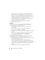
Unpacking Steps
NOTE: Before unpacking the switch, inspect the container and immediately report
any evidence of damage.
1
Place the container on a clean, flat surface and cut all straps securing the
container.
2
Open the container or remove the container top.
3
Carefully remove the switch from the container and place it on a secure
and clean surface.
4
Remove all packing material.
5
Inspect the product and accessories for damage.
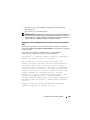
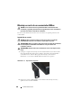
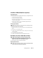
Rack Mounting a N20xx Switch
WARNING: Read the safety information in the Safety and Regulatory Information
as well as the safety information for other switches that connect to or support the
switch.
The AC power connector is on the back panel of the switch.
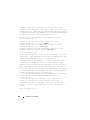
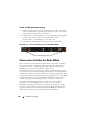
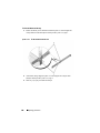
Installing in a Rack
WARNING: Do not use rack mounting kits to suspend the switch from under a
table or desk, or attach it to a wall.

16 Getting Started Guide
CAUTION: Disconnect all cables from the switch before continuing. Remove all
self-adhesive pads from the underside of the switch, if they have been attached.
CAUTION: When mounting multiple switches into a rack, mount the switches
from the bottom up.
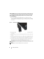
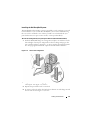
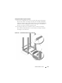
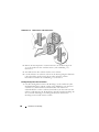
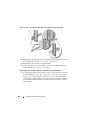
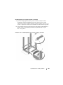
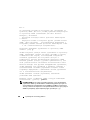
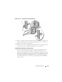
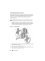
1
Place the supplied rack-mounting bracket on one side of the switch,
ensuring that the mounting holes on the switch line up to the mounting
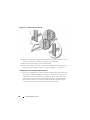
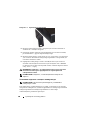
holes in the rack-mounting bracket. Figure 1-7 illustrates where to mount
the brackets.
Figure 1-7. Attaching the Brackets
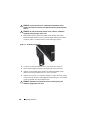
2
Insert the supplied bolts into the rack-mounting holes and tighten with a
screwdriver.
3
Repeat the process for the rack-mounting bracket on the other side of the
switch.
4
Insert the switch into the 48.26 cm (19 inch) rack, ensuring that the rack-
mounting holes on the switch line up to the mounting holes in the rack.
5
Secure the switch to the rack with either the rack bolts or cage nuts and
cage-nut bolts with washers (depending on the kind of rack you have).
Fasten the bolts on bottom before fastening the bolts on top.
CAUTION: Make sure that the supplied rack bolts fit the pre-threaded holes in the
rack.
NOTE: Make sure that the ventilation holes are not obstructed.

Getting Started Guide 17
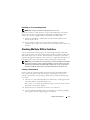
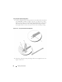
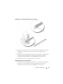
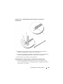
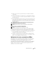
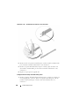
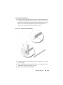
Installing as a Free-standing Switch
NOTE: We strongly recommend mounting the switch in a rack.
Install the switch on a flat surface if you are not installing it in a rack. The
surface must be able to support the weight of the switch and the switch
cables. The switch is supplied with four self-adhesive rubber pads.
1
Attach the self-adhesive rubber pads on each location marked on the
bottom of the switch.
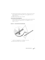
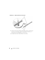
2
Set the switch on a flat surface, and make sure that it has proper
ventilation by leaving 5 cm (2 inches) on each side and 13 cm (5 inches) at
the back.
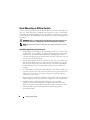
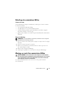
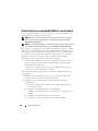
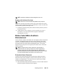
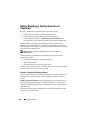
Stacking Multiple N20xx Switches
You can stack N20xx switches up to 12 switches high using the mini-SAS
ports located on the rear of the switch. N20xx switches support stacking only
with other N20xx series switches. When multiple switches are connected
together through the stack ports, they operate as a single unit with up to 576
front panel ports. The stack operates and is managed as a single entity.
NOTE: If you are installing a stack of switches, you need to assemble and cable the
stack before powering up and configuring it. When a stack is powered up for the
first time, the switches elect a Master Switch, which may occupy any location in
the stack. The Master LED on the front panel is illuminated on the master unit.
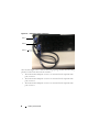
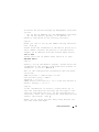
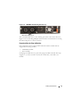
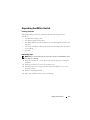
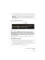
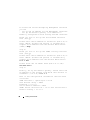
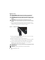
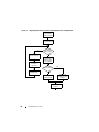
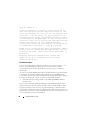
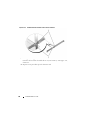
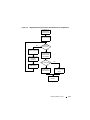
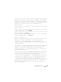
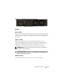
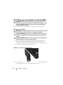
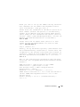
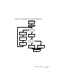
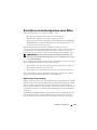
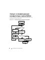
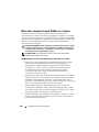
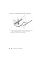
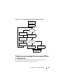
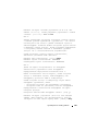
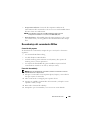
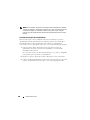
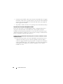
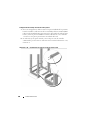
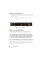
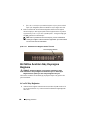
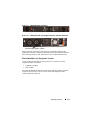
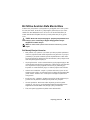
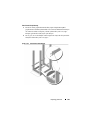
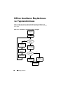
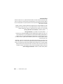
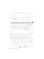
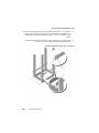
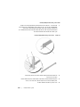
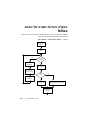
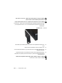
Creating a Switch Stack
Create a stack by connecting adjacent units using the mini-SAS stacking
ports on the back panel of the switch. Figure 1-8 on page 18 shows the
switches connected in a ring topology, which is the recommended topology
for a stack.
1
Connect one of the mini-SAS cables into either of the stacking ports of the
top switch and the switch directly below it.
If necessary, use a separately purchased, longer (1 meter or 3 meter) mini-
SAS cable to connect the switches.
2
Repeat this process until all of the devices are connected.
3
Use the remaining stacking cable to connect the two remaining stacking
ports together so that a ring topology is assembled.

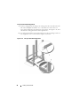
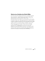
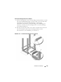
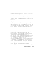
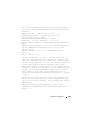
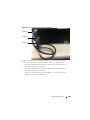
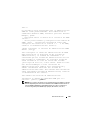
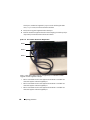
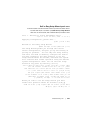
18 Getting Started Guide
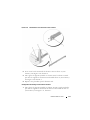
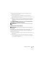
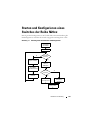
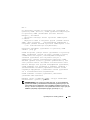
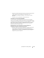
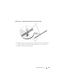
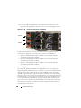
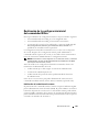
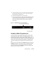
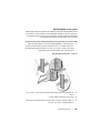
Figure 1-8. Connecting a Stack of Switches
The stack in Figure 1-8 is connected in a ring topology and has the following
physical connections between the switches:
• The bottom mini-SAS port on Unit 1 is connected to the top mini-SAS
port on Unit 2.
• The bottom mini-SAS port on Unit 2 is connected to the top mini-SAS
port on Unit 3.
• The bottom mini-SAS port on Unit 3 is connected to the top mini-SAS
port on Unit 1.
Unit 1
Unit 2
Unit 3
Sayfa yükleniyor...
Sayfa yükleniyor...
Sayfa yükleniyor...
Sayfa yükleniyor...
Sayfa yükleniyor...
Sayfa yükleniyor...
Sayfa yükleniyor...
Sayfa yükleniyor...
Sayfa yükleniyor...
Sayfa yükleniyor...
Sayfa yükleniyor...
Sayfa yükleniyor...
Sayfa yükleniyor...
Sayfa yükleniyor...
Sayfa yükleniyor...
Sayfa yükleniyor...
Sayfa yükleniyor...
Sayfa yükleniyor...
Sayfa yükleniyor...
Sayfa yükleniyor...
Sayfa yükleniyor...
Sayfa yükleniyor...
Sayfa yükleniyor...
Sayfa yükleniyor...
Sayfa yükleniyor...
Sayfa yükleniyor...
Sayfa yükleniyor...
Sayfa yükleniyor...
Sayfa yükleniyor...
Sayfa yükleniyor...
Sayfa yükleniyor...
Sayfa yükleniyor...
Sayfa yükleniyor...
Sayfa yükleniyor...
Sayfa yükleniyor...
Sayfa yükleniyor...
Sayfa yükleniyor...
Sayfa yükleniyor...
Sayfa yükleniyor...
Sayfa yükleniyor...
Sayfa yükleniyor...
Sayfa yükleniyor...
Sayfa yükleniyor...
Sayfa yükleniyor...
Sayfa yükleniyor...
Sayfa yükleniyor...
Sayfa yükleniyor...
Sayfa yükleniyor...
Sayfa yükleniyor...
Sayfa yükleniyor...
Sayfa yükleniyor...
Sayfa yükleniyor...
Sayfa yükleniyor...
Sayfa yükleniyor...
Sayfa yükleniyor...
Sayfa yükleniyor...
Sayfa yükleniyor...
Sayfa yükleniyor...
Sayfa yükleniyor...
Sayfa yükleniyor...
Sayfa yükleniyor...
Sayfa yükleniyor...
Sayfa yükleniyor...
Sayfa yükleniyor...
Sayfa yükleniyor...
Sayfa yükleniyor...
Sayfa yükleniyor...
Sayfa yükleniyor...
Sayfa yükleniyor...
Sayfa yükleniyor...
Sayfa yükleniyor...
Sayfa yükleniyor...
Sayfa yükleniyor...
Sayfa yükleniyor...
Sayfa yükleniyor...
Sayfa yükleniyor...
Sayfa yükleniyor...
Sayfa yükleniyor...
Sayfa yükleniyor...
Sayfa yükleniyor...
Sayfa yükleniyor...
Sayfa yükleniyor...
Sayfa yükleniyor...
Sayfa yükleniyor...
Sayfa yükleniyor...
Sayfa yükleniyor...
Sayfa yükleniyor...
Sayfa yükleniyor...
Sayfa yükleniyor...
Sayfa yükleniyor...
Sayfa yükleniyor...
Sayfa yükleniyor...
Sayfa yükleniyor...
Sayfa yükleniyor...
Sayfa yükleniyor...
Sayfa yükleniyor...
Sayfa yükleniyor...
Sayfa yükleniyor...
Sayfa yükleniyor...
Sayfa yükleniyor...
Sayfa yükleniyor...
Sayfa yükleniyor...
Sayfa yükleniyor...
Sayfa yükleniyor...
Sayfa yükleniyor...
Sayfa yükleniyor...
Sayfa yükleniyor...
Sayfa yükleniyor...
Sayfa yükleniyor...
Sayfa yükleniyor...
Sayfa yükleniyor...
Sayfa yükleniyor...
Sayfa yükleniyor...
Sayfa yükleniyor...
Sayfa yükleniyor...
Sayfa yükleniyor...
Sayfa yükleniyor...
Sayfa yükleniyor...
Sayfa yükleniyor...
Sayfa yükleniyor...
Sayfa yükleniyor...
Sayfa yükleniyor...
Sayfa yükleniyor...
Sayfa yükleniyor...
Sayfa yükleniyor...
Sayfa yükleniyor...
Sayfa yükleniyor...
Sayfa yükleniyor...
Sayfa yükleniyor...
Sayfa yükleniyor...
Sayfa yükleniyor...
Sayfa yükleniyor...
Sayfa yükleniyor...
Sayfa yükleniyor...
Sayfa yükleniyor...
Sayfa yükleniyor...
Sayfa yükleniyor...
Sayfa yükleniyor...
Sayfa yükleniyor...
Sayfa yükleniyor...
Sayfa yükleniyor...
Sayfa yükleniyor...
Sayfa yükleniyor...
Sayfa yükleniyor...
Sayfa yükleniyor...
Sayfa yükleniyor...
Sayfa yükleniyor...
Sayfa yükleniyor...
Sayfa yükleniyor...
Sayfa yükleniyor...
Sayfa yükleniyor...
Sayfa yükleniyor...
Sayfa yükleniyor...
Sayfa yükleniyor...
Sayfa yükleniyor...
Sayfa yükleniyor...
Sayfa yükleniyor...
Sayfa yükleniyor...
Sayfa yükleniyor...
Sayfa yükleniyor...
Sayfa yükleniyor...
Sayfa yükleniyor...
Sayfa yükleniyor...
Sayfa yükleniyor...
Sayfa yükleniyor...
Sayfa yükleniyor...
Sayfa yükleniyor...
Sayfa yükleniyor...
Sayfa yükleniyor...
Sayfa yükleniyor...
Sayfa yükleniyor...
Sayfa yükleniyor...
Sayfa yükleniyor...
Sayfa yükleniyor...
Sayfa yükleniyor...
Sayfa yükleniyor...
Sayfa yükleniyor...
Sayfa yükleniyor...
Sayfa yükleniyor...
Sayfa yükleniyor...
Sayfa yükleniyor...
Sayfa yükleniyor...
Sayfa yükleniyor...
Sayfa yükleniyor...
Sayfa yükleniyor...
Sayfa yükleniyor...
Sayfa yükleniyor...
Sayfa yükleniyor...
Sayfa yükleniyor...
Sayfa yükleniyor...
Sayfa yükleniyor...
Sayfa yükleniyor...
Sayfa yükleniyor...
Sayfa yükleniyor...
Sayfa yükleniyor...
Sayfa yükleniyor...
Sayfa yükleniyor...
Sayfa yükleniyor...
Sayfa yükleniyor...
Sayfa yükleniyor...
Sayfa yükleniyor...
Sayfa yükleniyor...
Sayfa yükleniyor...
Sayfa yükleniyor...
Sayfa yükleniyor...
Sayfa yükleniyor...
Sayfa yükleniyor...
Sayfa yükleniyor...
Sayfa yükleniyor...
Sayfa yükleniyor...
Sayfa yükleniyor...
Sayfa yükleniyor...
Sayfa yükleniyor...
Sayfa yükleniyor...
Sayfa yükleniyor...
Sayfa yükleniyor...
Sayfa yükleniyor...
Sayfa yükleniyor...
Sayfa yükleniyor...
Sayfa yükleniyor...
Sayfa yükleniyor...
Sayfa yükleniyor...
Sayfa yükleniyor...
Sayfa yükleniyor...
Sayfa yükleniyor...
Sayfa yükleniyor...
Sayfa yükleniyor...
Sayfa yükleniyor...
Sayfa yükleniyor...
Sayfa yükleniyor...
Sayfa yükleniyor...
Sayfa yükleniyor...
Sayfa yükleniyor...
Sayfa yükleniyor...
Sayfa yükleniyor...
Sayfa yükleniyor...
Sayfa yükleniyor...
Sayfa yükleniyor...
Sayfa yükleniyor...
Sayfa yükleniyor...
Sayfa yükleniyor...
Sayfa yükleniyor...
Sayfa yükleniyor...
Sayfa yükleniyor...
Sayfa yükleniyor...
Sayfa yükleniyor...
Sayfa yükleniyor...
Sayfa yükleniyor...
Sayfa yükleniyor...
Sayfa yükleniyor...
Sayfa yükleniyor...
Sayfa yükleniyor...
Sayfa yükleniyor...
Sayfa yükleniyor...
Sayfa yükleniyor...
Sayfa yükleniyor...
Sayfa yükleniyor...
Sayfa yükleniyor...
Sayfa yükleniyor...
Sayfa yükleniyor...
Sayfa yükleniyor...
Sayfa yükleniyor...
Sayfa yükleniyor...
Sayfa yükleniyor...
Sayfa yükleniyor...
Sayfa yükleniyor...
Sayfa yükleniyor...
Sayfa yükleniyor...
Sayfa yükleniyor...
Sayfa yükleniyor...
Sayfa yükleniyor...
Sayfa yükleniyor...
Sayfa yükleniyor...
Sayfa yükleniyor...
Sayfa yükleniyor...
Sayfa yükleniyor...
Sayfa yükleniyor...
Sayfa yükleniyor...
Sayfa yükleniyor...
Sayfa yükleniyor...
Sayfa yükleniyor...
Sayfa yükleniyor...
Sayfa yükleniyor...
Sayfa yükleniyor...
Sayfa yükleniyor...
Sayfa yükleniyor...
Sayfa yükleniyor...
Sayfa yükleniyor...
Sayfa yükleniyor...
Sayfa yükleniyor...
Sayfa yükleniyor...
Sayfa yükleniyor...
Sayfa yükleniyor...
Sayfa yükleniyor...
Sayfa yükleniyor...
Sayfa yükleniyor...
Sayfa yükleniyor...
Sayfa yükleniyor...
Sayfa yükleniyor...
Sayfa yükleniyor...
Sayfa yükleniyor...
Sayfa yükleniyor...
Sayfa yükleniyor...
Sayfa yükleniyor...
Sayfa yükleniyor...
Sayfa yükleniyor...
Sayfa yükleniyor...
Sayfa yükleniyor...
Sayfa yükleniyor...
Sayfa yükleniyor...
Sayfa yükleniyor...
Sayfa yükleniyor...
Sayfa yükleniyor...
Sayfa yükleniyor...
Sayfa yükleniyor...
Sayfa yükleniyor...
Sayfa yükleniyor...
Sayfa yükleniyor...
Sayfa yükleniyor...
Sayfa yükleniyor...
Sayfa yükleniyor...
Sayfa yükleniyor...
Sayfa yükleniyor...
Sayfa yükleniyor...
Sayfa yükleniyor...
Sayfa yükleniyor...
Sayfa yükleniyor...
Sayfa yükleniyor...
Sayfa yükleniyor...
Sayfa yükleniyor...
Sayfa yükleniyor...
Sayfa yükleniyor...
Sayfa yükleniyor...
Sayfa yükleniyor...
Sayfa yükleniyor...
Sayfa yükleniyor...
Sayfa yükleniyor...
Sayfa yükleniyor...
Sayfa yükleniyor...
Sayfa yükleniyor...
Sayfa yükleniyor...
Sayfa yükleniyor...
Sayfa yükleniyor...
Sayfa yükleniyor...
Sayfa yükleniyor...
Sayfa yükleniyor...
Sayfa yükleniyor...
Sayfa yükleniyor...
Sayfa yükleniyor...
Sayfa yükleniyor...
Sayfa yükleniyor...
Sayfa yükleniyor...
Sayfa yükleniyor...
Sayfa yükleniyor...
Sayfa yükleniyor...
Sayfa yükleniyor...
Sayfa yükleniyor...
Sayfa yükleniyor...
Sayfa yükleniyor...
Sayfa yükleniyor...
Sayfa yükleniyor...
Sayfa yükleniyor...
Sayfa yükleniyor...
Sayfa yükleniyor...
Sayfa yükleniyor...
Sayfa yükleniyor...
Sayfa yükleniyor...
Sayfa yükleniyor...
Sayfa yükleniyor...
Sayfa yükleniyor...
Sayfa yükleniyor...
Sayfa yükleniyor...
Sayfa yükleniyor...
Sayfa yükleniyor...
Sayfa yükleniyor...
Sayfa yükleniyor...
Sayfa yükleniyor...
Sayfa yükleniyor...
Sayfa yükleniyor...
Sayfa yükleniyor...
Sayfa yükleniyor...
Sayfa yükleniyor...
Sayfa yükleniyor...
Sayfa yükleniyor...
Sayfa yükleniyor...
Sayfa yükleniyor...
Sayfa yükleniyor...
Sayfa yükleniyor...
Sayfa yükleniyor...
Sayfa yükleniyor...
Sayfa yükleniyor...
Sayfa yükleniyor...
Sayfa yükleniyor...
Sayfa yükleniyor...
Sayfa yükleniyor...
Sayfa yükleniyor...
Sayfa yükleniyor...
Sayfa yükleniyor...
Sayfa yükleniyor...
Sayfa yükleniyor...
Sayfa yükleniyor...
Sayfa yükleniyor...
Sayfa yükleniyor...
Sayfa yükleniyor...
Sayfa yükleniyor...
Sayfa yükleniyor...
Sayfa yükleniyor...
Sayfa yükleniyor...
Sayfa yükleniyor...
Sayfa yükleniyor...
Sayfa yükleniyor...
Sayfa yükleniyor...
Sayfa yükleniyor...
Sayfa yükleniyor...
Sayfa yükleniyor...
Sayfa yükleniyor...
Sayfa yükleniyor...
Sayfa yükleniyor...
Sayfa yükleniyor...
Sayfa yükleniyor...
Sayfa yükleniyor...
Sayfa yükleniyor...
Sayfa yükleniyor...
Sayfa yükleniyor...
Sayfa yükleniyor...
Sayfa yükleniyor...
Sayfa yükleniyor...
Sayfa yükleniyor...
Sayfa yükleniyor...
Sayfa yükleniyor...
Sayfa yükleniyor...
Sayfa yükleniyor...
Sayfa yükleniyor...
Sayfa yükleniyor...
Sayfa yükleniyor...
Sayfa yükleniyor...
Sayfa yükleniyor...
Sayfa yükleniyor...
Sayfa yükleniyor...
Sayfa yükleniyor...
Sayfa yükleniyor...
Sayfa yükleniyor...
-
 1
1
-
 2
2
-
 3
3
-
 4
4
-
 5
5
-
 6
6
-
 7
7
-
 8
8
-
 9
9
-
 10
10
-
 11
11
-
 12
12
-
 13
13
-
 14
14
-
 15
15
-
 16
16
-
 17
17
-
 18
18
-
 19
19
-
 20
20
-
 21
21
-
 22
22
-
 23
23
-
 24
24
-
 25
25
-
 26
26
-
 27
27
-
 28
28
-
 29
29
-
 30
30
-
 31
31
-
 32
32
-
 33
33
-
 34
34
-
 35
35
-
 36
36
-
 37
37
-
 38
38
-
 39
39
-
 40
40
-
 41
41
-
 42
42
-
 43
43
-
 44
44
-
 45
45
-
 46
46
-
 47
47
-
 48
48
-
 49
49
-
 50
50
-
 51
51
-
 52
52
-
 53
53
-
 54
54
-
 55
55
-
 56
56
-
 57
57
-
 58
58
-
 59
59
-
 60
60
-
 61
61
-
 62
62
-
 63
63
-
 64
64
-
 65
65
-
 66
66
-
 67
67
-
 68
68
-
 69
69
-
 70
70
-
 71
71
-
 72
72
-
 73
73
-
 74
74
-
 75
75
-
 76
76
-
 77
77
-
 78
78
-
 79
79
-
 80
80
-
 81
81
-
 82
82
-
 83
83
-
 84
84
-
 85
85
-
 86
86
-
 87
87
-
 88
88
-
 89
89
-
 90
90
-
 91
91
-
 92
92
-
 93
93
-
 94
94
-
 95
95
-
 96
96
-
 97
97
-
 98
98
-
 99
99
-
 100
100
-
 101
101
-
 102
102
-
 103
103
-
 104
104
-
 105
105
-
 106
106
-
 107
107
-
 108
108
-
 109
109
-
 110
110
-
 111
111
-
 112
112
-
 113
113
-
 114
114
-
 115
115
-
 116
116
-
 117
117
-
 118
118
-
 119
119
-
 120
120
-
 121
121
-
 122
122
-
 123
123
-
 124
124
-
 125
125
-
 126
126
-
 127
127
-
 128
128
-
 129
129
-
 130
130
-
 131
131
-
 132
132
-
 133
133
-
 134
134
-
 135
135
-
 136
136
-
 137
137
-
 138
138
-
 139
139
-
 140
140
-
 141
141
-
 142
142
-
 143
143
-
 144
144
-
 145
145
-
 146
146
-
 147
147
-
 148
148
-
 149
149
-
 150
150
-
 151
151
-
 152
152
-
 153
153
-
 154
154
-
 155
155
-
 156
156
-
 157
157
-
 158
158
-
 159
159
-
 160
160
-
 161
161
-
 162
162
-
 163
163
-
 164
164
-
 165
165
-
 166
166
-
 167
167
-
 168
168
-
 169
169
-
 170
170
-
 171
171
-
 172
172
-
 173
173
-
 174
174
-
 175
175
-
 176
176
-
 177
177
-
 178
178
-
 179
179
-
 180
180
-
 181
181
-
 182
182
-
 183
183
-
 184
184
-
 185
185
-
 186
186
-
 187
187
-
 188
188
-
 189
189
-
 190
190
-
 191
191
-
 192
192
-
 193
193
-
 194
194
-
 195
195
-
 196
196
-
 197
197
-
 198
198
-
 199
199
-
 200
200
-
 201
201
-
 202
202
-
 203
203
-
 204
204
-
 205
205
-
 206
206
-
 207
207
-
 208
208
-
 209
209
-
 210
210
-
 211
211
-
 212
212
-
 213
213
-
 214
214
-
 215
215
-
 216
216
-
 217
217
-
 218
218
-
 219
219
-
 220
220
-
 221
221
-
 222
222
-
 223
223
-
 224
224
-
 225
225
-
 226
226
-
 227
227
-
 228
228
-
 229
229
-
 230
230
-
 231
231
-
 232
232
-
 233
233
-
 234
234
-
 235
235
-
 236
236
-
 237
237
-
 238
238
-
 239
239
-
 240
240
-
 241
241
-
 242
242
-
 243
243
-
 244
244
-
 245
245
-
 246
246
-
 247
247
-
 248
248
-
 249
249
-
 250
250
-
 251
251
-
 252
252
-
 253
253
-
 254
254
-
 255
255
-
 256
256
-
 257
257
-
 258
258
-
 259
259
-
 260
260
-
 261
261
-
 262
262
-
 263
263
-
 264
264
-
 265
265
-
 266
266
-
 267
267
-
 268
268
-
 269
269
-
 270
270
-
 271
271
-
 272
272
-
 273
273
-
 274
274
-
 275
275
-
 276
276
-
 277
277
-
 278
278
-
 279
279
-
 280
280
-
 281
281
-
 282
282
-
 283
283
-
 284
284
-
 285
285
-
 286
286
-
 287
287
-
 288
288
-
 289
289
-
 290
290
-
 291
291
-
 292
292
-
 293
293
-
 294
294
-
 295
295
-
 296
296
-
 297
297
-
 298
298
-
 299
299
-
 300
300
-
 301
301
-
 302
302
-
 303
303
-
 304
304
-
 305
305
-
 306
306
-
 307
307
-
 308
308
-
 309
309
-
 310
310
-
 311
311
-
 312
312
-
 313
313
-
 314
314
-
 315
315
-
 316
316
-
 317
317
-
 318
318
-
 319
319
-
 320
320
-
 321
321
-
 322
322
-
 323
323
-
 324
324
-
 325
325
-
 326
326
-
 327
327
-
 328
328
-
 329
329
-
 330
330
-
 331
331
-
 332
332
-
 333
333
-
 334
334
-
 335
335
-
 336
336
-
 337
337
-
 338
338
-
 339
339
-
 340
340
-
 341
341
-
 342
342
-
 343
343
-
 344
344
-
 345
345
-
 346
346
-
 347
347
-
 348
348
-
 349
349
-
 350
350
-
 351
351
-
 352
352
-
 353
353
-
 354
354
-
 355
355
-
 356
356
-
 357
357
-
 358
358
-
 359
359
-
 360
360
-
 361
361
-
 362
362
-
 363
363
-
 364
364
-
 365
365
-
 366
366
-
 367
367
-
 368
368
-
 369
369
-
 370
370
-
 371
371
-
 372
372
-
 373
373
-
 374
374
-
 375
375
-
 376
376
-
 377
377
-
 378
378
-
 379
379
-
 380
380
-
 381
381
-
 382
382
-
 383
383
-
 384
384
-
 385
385
-
 386
386
-
 387
387
-
 388
388
-
 389
389
-
 390
390
-
 391
391
-
 392
392
-
 393
393
-
 394
394
-
 395
395
-
 396
396
-
 397
397
-
 398
398
-
 399
399
-
 400
400
-
 401
401
-
 402
402
-
 403
403
-
 404
404
-
 405
405
-
 406
406
-
 407
407
-
 408
408
-
 409
409
-
 410
410
-
 411
411
-
 412
412
-
 413
413
-
 414
414
-
 415
415
-
 416
416
-
 417
417
-
 418
418
-
 419
419
-
 420
420
-
 421
421
-
 422
422
-
 423
423
-
 424
424
-
 425
425
-
 426
426
-
 427
427
-
 428
428
-
 429
429
-
 430
430
-
 431
431
-
 432
432
-
 433
433
-
 434
434
-
 435
435
-
 436
436
-
 437
437
-
 438
438
-
 439
439
-
 440
440
-
 441
441
-
 442
442
-
 443
443
-
 444
444
-
 445
445
-
 446
446
-
 447
447
-
 448
448
-
 449
449
-
 450
450
-
 451
451
-
 452
452
-
 453
453
-
 454
454
-
 455
455
-
 456
456
-
 457
457
-
 458
458
-
 459
459
-
 460
460
-
 461
461
-
 462
462


Dell N20XX Kullanım kılavuzu
- Kategori
- Ağ anahtarları
- Tip
- Kullanım kılavuzu
- Bu kılavuz aynı zamanda aşağıdakiler için de uygundur:
diğer dillerde
- español: Dell N20XX Manual de usuario
- français: Dell N20XX Manuel utilisateur
İlgili makaleler
-
Dell PowerSwitch N1500 Series Hızlı başlangıç Kılavuzu
-
-
-
-
-
-
-
Dell PowerSwitch N1100-ON Series Hızlı başlangıç Kılavuzu
-