Yamaha MGP12X Kullanım kılavuzu
- Kategori
- Ses mikserleri
- Tip
- Kullanım kılavuzu
Bu kılavuz aynı zamanda aşağıdakiler için de uygundur:


MGP16X/MGP12X Owner’s Manual
2
IMPORTANT SAFETY
INSTRUCTIONS
1 Read these instructions.
2 Keep these instructions.
3 Heed all warnings.
4 Follow all instructions.
5 Do not use this apparatus near water.
6 Clean only with dry cloth.
7 Do not block any ventilation openings. Install in accordance with the
manufacturer’s instructions.
8 Do not install near any heat sources such as radiators, heat registers,
stoves, or other apparatus (including amplifiers) that produce heat.
9 Do not defeat the safety purpose of the polarized or grounding-type plug.
A polarized plug has two blades with one wider than the other. A ground-
ing type plug has two blades and a third grounding prong. The wide
blade or the third prong are provided for your safety. If the provided plug
does not fit into your outlet, consult an electrician for replacement of the
obsolete outlet.
10 Protect the power cord from being walked on or pinched particularly at
plugs, convenience receptacles, and the point where they exit from the
apparatus.
11 Only use attachments/accessories specified by the manufacturer.
12 Use only with the cart, stand, tripod, bracket, or table
specified by the manufacturer, or sold with the appa-
ratus. When a cart is used, use caution when moving
the cart/apparatus combination to avoid injury from
tip-over.
13 Unplug this apparatus during lightning storms or
when unused for long periods of time.
14 Refer all servicing to qualified service personnel. Servicing is required
when the apparatus has been damaged in any way, such as power-sup-
ply cord or plug is damaged, liquid has been spilled or objects have
fallen into the apparatus, the apparatus has been exposed to rain or
moisture, does not operate normally, or has been dropped.
(UL60065_03)
PRÉCAUTIONS CONCER-
NANT LA SÉCURITÉ
1 Lire ces instructions.
2 Conserver ces instructions.
3 Tenir compte de tous les avertissements.
4 Suivre toutes les instructions.
5 Ne pas utiliser ce produit à proximité d’eau.
6 Nettoyer uniquement avec un chiffon propre et sec.
7 Ne pas bloquer les orifices de ventilation. Installer l’appareil conformém-
ent aux instructions du fabricant.
8 Ne pas installer l’appareil à proximité d’une source de chaleur comme un
radiateur, une bouche de chaleur, un poêle ou tout autre appareil (y com-
pris un amplificateur) produisant de la chaleur.
9 Ne pas modifier le système de sécurité de la fiche polarisée ou de la fiche
de terre. Une fiche polarisée dispose de deux broches dont une est plus
large que l’autre. Une fiche de terre dispose de deux broches et d’une
troisième pour le raccordement à la terre. Cette broche plus large ou
cette troisième broche est destinée à assurer la sécurité de l’utilisateur.
Si la fiche équipant l’appareil n’est pas compatible avec les prises de
courant disponibles, faire remplacer les prises par un électricien.
10 Acheminer les cordons d’alimentation de sorte qu’ils ne soient pas piét-
inés ni coincés, en faisant tout spécialement attention aux fiches, prises
de courant et au point de sortie de l’appareil.
11 Utiliser exclusivement les fixations et accessoires spécifiés par le fabri-
cant.
12 Utiliser exclusivement le chariot, le stand, le trépied,
le support ou la table recommandés par le fabricant
ou vendus avec cet appareil. Si l’appareil est posé sur
un chariot, déplacer le chariot avec précaution pour
éviter tout risque de chute et de blessure.
13 Débrancher l’appareil en cas d’orage ou lorsqu’il doit
rester hors service pendant une période prolongée.
14 Confier toute réparation à un personnel qualifié. Faire réparer l’appareil
s’il a subi tout dommage, par exemple si la fiche ou le cordon d’alimenta-
tion est endommagé, si du liquide a coulé ou des objets sont tombés à
l’intérieur de l’appareil, si l’appareil a été exposé à la pluie ou à de l’humi-
dité, si l’appareil ne fonctionne pas normalement ou est tombé.
(UL60065_03)
CAUTION: TO REDUCE THE RISK OF
ELECTRIC SHOCK, DO NOT REMOVE
COVER (OR BACK). NO USER-SERVICEABLE
PARTS INSIDE. REFER SERVICING TO
QUALIFIED SERVICE PERSONNEL.
CAUTION
RISK OF ELECTRIC SHOCK
DO NOT OPEN
Explanation of Graphical Symbols
Explication des symboles
The lightning flash with arrowhead symbol within an equilateral tri-
angle is intended to alert the user to the presence of uninsulated
“dangerous voltage” within the product’s enclosure that may be of
sufficient magnitude to constitute a risk of electric shock to persons.
L’éclair avec une flèche à l’intérieur d’un triangle équilatéral est
destiné à attirer l’attention de l’utilisateur sur la présence d’une «
tension dangereuse » non isolée à l’intérieur de l’appareil, pouvant
être suffisamment élevée pour constituer un risque d’électrocution.
The exclamation point within an equilateral triangle is intended to
alert the user to the presence of important operating and mainte-
nance (servicing) instructions in the literature accompanying the
product.
Le point d’exclamation à l’intérieur d’un triangle équilatéral est des-
tiné à attirer l’attention de l’utilisateur sur la présence d’instructions
importantes sur l’emploi ou la maintenance (réparation) de l’appa-
reil dans la documentation fournie.
The above warning is located on the rear of the unit.
L’avertissement ci-dessus est situé sur le arrière de l’appareil.
WARNING
TO REDUCE THE RISK OF FIRE OR ELECTRIC SHOCK, DO NOT EXPOSE
THIS APPARATUS TO RAIN OR MOISTURE.
AVERTISSEMENT
POUR RÉDUIRE LES RISQUES D’INCENDIE OU DE DÉCHARGE ÉLECTRI-
QUE, N’EXPOSEZ PAS CET APPAREIL À LA PLUIE OU À L’HUMIDITÉ.
Thank you for your purchase of the Yamaha MGP16X or MGP12X mixing console.
Please read this manual thoroughly to make the best use of the mixing console for the
longest possible period of time.
After reading this manual, please keep it available for future reference.

MGP16X/MGP12X Owner’s Manual
3
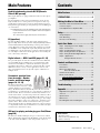
Main Features ................................ 3
PRECAUTIONS.................................4
Making the Most of Your Mixer............ 6
Balanced Cables and Unbalanced Cables ...........6
Connector Types...................................................6
Level Adjustment for Optimum Mix .......................7
Setup ........................................... 8
Setup Examples....................................................8
Rack Mounting.................................................... 10
Security Cover Mounting .................................... 11
Quick Start Guide ...........................12
Step 1 Preparing the Power Supply ...................12
Step 2 Connections ........................................... 12
Step 3 Powering Up the System ........................12
Step 4 Getting Sound to the Speakers...............13
Step 5 Using the Built-in Digital Effects ............. 13
Step 6 <Application>
Using the Ducker function.......................14
Controls and Connectors...................15
Front Panel ......................................................... 15
Rear Panel..........................................................16
Where Your Signal Goes
Once It’s Inside the Box..........................17
Channel Control Block........................................18
Master Control Block...........................................20
About the Detailed Setting Mode......................21
Rear Input/Output Block .....................................25
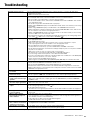
Troubleshooting .............................27
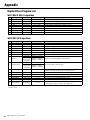
Appendix......................................28
Digital Effect Program List...................................28
Jack List..............................................................29
Specifications......................................................30
Dimensions.........................................................32
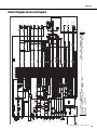
Block Diagram and Level Diagram......................33
ContentsMain Features
Sophisticated analog circuits D-PRE (Discrete
Class-A MIC preamp)
Mono input channels are equipped with Class-A discrete microphone
preamplifiers.
The head amplifier features an inverted Darlington circuit* used in
high-end audio devices, and reproduces low frequencies with excep-
tionally musical characteristics as well as sustained high frequencies.
Independent toggle switching of +48V phantom power and 26dB (pad)
on each channel.
* Inverted Darlington circuit: An amplifying method for eliminating the
nonlinear characteristics of the amplifier element and suppress-
ing the distortion.
The circuit features highly musical phase characteristics.
EQ (equalizer)
The shelving EQ (low/high) on the mono input channels features
Xpressive EQ, which effectively models analog EQ utilizing Yamaha’s
famed VCM (Virtual Circuitry Modeling) technology. We analyzed
vintage EQ analog circuits and redesigned the technology specifically
for the MGP to create an EQ with exceptionally musical characteris-
tics. Furthermore, the cutoff frequency can also be adjusted, enhancing
use of the EQ in sound reinforcement applications, and extending the
sonic control range of the mixer.
Digital effects — REV-X and SPX (pages 21, 28)
Two powerful digital effect blocks are built into the mixer: REV-X (8
types) and SPX (16 types). REV-X gives you a high-density, richly
reverberant sound ambience, with smooth attenuation, spread and
depth that work together to enhance the original sound. The versatile
SPX block features a variety of effect applications, such as reverb,
delay, and modulation effects, along with complex combinations of
multiple effects.
Convenient, practical func-
tions for events – Ducker,
Leveler, and Stereo Image
(pages 14, 18, 19)
The mixer features three exceptionally
convenient features for the stereo input
channels: Ducker, Leveler and Stereo
Image. The Ducker function automatically lowers the level of back-
ground music to accommodate the voice of an announcer coming in on
another channel. The Leveler function automatically maintains a con-
sistent sound volume, even when using sound sources that have differ-
ent mastering levels, such as on an iPod/iPhone filled with a variety of
sources classified according to different genres and ages. Stereo Image
narrows the pan balance of the stereo sound source, and changes stereo
signals to mono. This is useful in restaurants and other spaces where
the left and right speakers are distantly positioned, or when you input
accompaniment sound to the left channel and vocal sound to the right
and want a more natural stereo image.
USB port for playing and charging your iPod/iPhone
(page 20)
The mixer has a built-in USB port (at top) for connection to an iPod/
iPhone. Digital audio output from the iPod/iPhone can be directly input
to the unit, and the iPod/iPhone can be charged while connected.
Accessories
• AC power cord (1)
• Rack mount kit (1) (MGP12X only)
• Owner’s manual (1)

MGP16X/MGP12X Owner’s Manual
4
PRECAUTIONS
PLEASE READ CAREFULLY BEFORE PROCEEDING
* Please keep this manual in a safe place for future reference.
WARNING
Always follow the basic precautions listed below to avoid the possibility of serious injury or even death from
electrical shock, short-circuiting, damages, fire or other hazards. These precautions include, but are not limited to,
the following:
• Do not place the power cord near heat sources such as heaters or radiators,
and do not excessively bend or otherwise damage the cord, place heavy
objects on it, or place it in a position where anyone could walk on, trip over,
or roll anything over it.
• Only use the voltage specified as correct for the device. The required voltage
is printed on the name plate of the device.
• Use only the supplied power cord/plug.
If you intend to use the device in an area other than in the one you purchased,
the included power cord may not be compatible. Please check with your
Yamaha dealer.
• Check the electric plug periodically and remove any dirt or dust which may
have accumulated on it.
• Be sure to connect to an appropriate outlet with a protective grounding
connection. Improper grounding can result in electrical shock.
• This device contains no user-serviceable parts. Do not open the device or
attempt to disassemble the internal parts or modify them in any way. If it
should appear to1 be malfunctioning, discontinue use immediately and have
it inspected by qualified Yamaha service personnel.
• Do not expose the device to rain, use it near water or in damp or wet
conditions, or place on it any containers (such as vases, bottles or glasses)
containing liquids which might spill into any openings. If any liquid such as
water seeps into the device, turn off the power immediately and unplug the
power cord from the AC outlet. Then have the device inspected by qualified
Yamaha service personnel.
• Never insert or remove an electric plug with wet hands.
• Do not put burning items, such as candles, on the unit. A burning item may
fall over and cause a fire.
• When one of the following problems occur, immediately turn off the power
switch and disconnect the electric plug from the outlet. Then have the device
inspected by Yamaha service personnel.
- The power cord or plug becomes frayed or damaged.
- It emits unusual smells or smoke.
- Some object has been dropped into the instrument.
- There is a sudden loss of sound during use of the device.
• If this device should be dropped or damaged, immediately turn off the power
switch, disconnect the electric plug from the outlet, and have the device
inspected by qualified Yamaha service personnel.
CAUTION
Always follow the basic precautions listed below to avoid the possibility of physical injury to you or others, or
damage to the device or other property. These precautions include, but are not limited to, the following:
• When removing the electric plug from the device or an outlet, always hold the
plug itself and not the cord. Pulling by the cord can damage it.
• Remove the electric plug from the outlet when the device is not to be used for
extended periods of time, or during electrical storms.
• Do not place the device in an unstable position where it might accidentally
fall over.
• Do not block the vents. This device has ventilation holes at the bottom and
sides to prevent the internal temperature from becoming too high. In
particular, do not place the device on its side or upside down. Inadequate
ventilation can result in overheating, possibly causing damage to the
device(s), or even fire.
• Do not place the device in a location where it may come into contact with
corrosive gases or salt air. Doing so may result in malfunction.
• Before moving the device, remove all connected cables.
• When setting up the device, make sure that the AC outlet you are using is
easily accessible. If some trouble or malfunction occurs, immediately turn off
the power switch and disconnect the plug from the outlet. Even when the
power switch is turned off, electricity is still flowing to the product at the
minimum level. When you are not using the product for a long time, make
sure to unplug the power cord from the wall AC outlet.
• If the device is mounted in an EIA standard rack, carefully read the section
“Precautions for Rack Mounting” on page 10. Inadequate ventilation can
result in overheating, possibly causing damage to the device(s), malfunction,
or even fire.
• Before connecting the device to other devices, turn off the power for all
devices. Before turning the power on or off for all devices, set all volume
levels to minimum.
Power supply/Power cord
Do not open
Water warning
Fire warning
If you notice any abnormality
Power supply/Power cord
Location
Connections
PA_en_1 1/2

MGP16X/MGP12X Owner’s Manual
5
• Remove the power plug from the AC outlet when cleaning the device.
• Do not insert your fingers or hands in any gaps or openings on the device
(vents, ports, etc.).
• Avoid inserting or dropping foreign objects (paper, plastic, metal, etc.) into
any gaps or openings on the device (vents, ports, etc.) If this happens, turn
off the power immediately and unplug the power cord from the AC outlet.
Then have the device inspected by qualified Yamaha service personnel.
• Do not rest your weight on the device or place heavy objects on it, and avoid
use excessive force on the buttons, switches or connectors.
• Do not use speakers or headphones for a long period of time at a high or
uncomfortable volume level, since this can cause permanent hearing loss. If
you experience any hearing loss or ringing in the ears, consult a physician.
Always turn the power off when the device is not in use.
NOTICE
To avoid the possibility of malfunction/damage to the prod-
uct, damage to data, or damage to other property, follow the
notices below.
Handling and Maintenance
• Do not use the device in the vicinity of a TV, radio, stereo
equipment, mobile phone, or other electric devices. Oth-
erwise, the device, TV, or radio may generate noise.
• Do not expose the device to excessive dust or vibrations,
or extreme cold or heat (such as in direct sunlight, near a
heater, or in a car during the day) to prevent the possibility
of panel disfiguration, damage to the internal components
or unstable operation.
• Do not place vinyl, plastic or rubber objects on the device,
since this might discolor the panel of this device.
• When cleaning the device, use a dry and soft cloth. Do
not use paint thinners, solvents, cleaning fluids, or chemi-
cal-impregnated wiping cloths.
• Condensation can occur in the device due to rapid, dras-
tic changes in ambient temperature—when the device is
moved from one location to another, or air conditioning is
turned on or off, for example. Using the device while con-
densation is present can cause damage. If there is reason
to believe that condensation might have occurred, leave
the device for several hours without turning on the power
until the condensation has completely dried out.
• Avoid setting all equalizer controls and faders to their
maximum. Depending on the condition of the connected
devices, doing so may cause feedback and may damage
the speakers.
• Do not apply oil, grease, or contact cleaner to the faders.
Doing so may cause problems with electrical contact or
fader motion.
• When turning on the AC power in your audio system,
always turn on the power amplifier LAST, to avoid speaker
damage. When turning the power off, the power amplifier
should be turned off FIRST for the same reason.
Connectors
XLR-type connectors are wired as follows (IEC60268 stan-
dard): pin 1: ground, pin 2: hot (+), and pin 3: cold (-).
Insert TRS phone jacks are wired as follows: sleeve:
ground, tip: send, and ring: return.
Information
About copyrights
• Copying of the commercially available musical data including but
not limited to MIDI data and/or audio data is strictly prohibited
except for your personal use.
About this manual
• The illustrations as shown in this manual are for instructional pur-
poses only, and may appear somewhat different from those on
your device.
• Throughout this manual, all panel illustrations show the panel of
the MGP16X.
• In this manual the term “MGP” refers to both the MGP16X and
MGP12X. In cases where different features need to be described
for each model, the MGP16X feature will be described first, fol-
lowed by the MGP12X feature in brackets: MGP16X (MGP12X).
• The company names and product names in this manual are the
trademarks or registered trademarks of their respective compa-
nies.
iPod
TM
, iPhone
TM
iPhone, iPod, iPod classic, iPod nano, and iPod touch are
trademarks of Apple Inc., registered in the U.S. and other
countries.
“Made for iPod” and “Made for iPhone” mean that an elec-
tronic accessory has been designed to connect specifically
to iPod or iPhone respectively, and has been certified by the
developer to meet Apple performance standards. Apple is
not responsible for the operation of this device or its compli-
ance with safety and regulatory standards. Please note that
the use of this accessory with iPod or iPhone may affect
wireless performance.
Maintenance
Handling caution
Yamaha cannot be held responsible for damage caused by improper use
or modifications to the device, or data that is lost or destroyed.
PA_en_1 2/2

MGP16X/MGP12X Owner’s Manual
6
Making the Most of Your Mixer
Balanced Cables and Unbal-
anced Cables
Two types of cables can be used to connect microphones, elec-
tronic instruments, and other audio sources to the mixer’s inputs,
as well as to connect the mixer’s outputs to a power amplifier or
related gear: balanced or unbalanced.
Balanced cables are highly resistant to noise, and are the best
choice for low-level signals such as the output from microphones,
as well as for long cable runs. Unbalanced cables are generally
used for short runs from line-level sources such as synthesizers.
Cable Guidelines
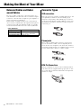
Connector Types
XLR connectors
This 3-pin connector is resistant to externally induced noise, and
is used primarily for balanced connections. With properly
designed receiving circuitry, cables with this type of connector
can also be used for unbalanced signals. XLR type connectors are
the standard for microphone connections as well as most profes-
sional audio gear.
Phone jacks
Phone jacks are available in mono and stereo versions. Stereo
types are also known as “TRS” connectors (Tip-Ring-Sleeve),
and are used for stereo headphone jacks, insert jacks, and also to
carry balanced signals in many cases. Unbalanced types are used
for mono signals -guitar cables are a common example.
RCA Pin Connectors
This type of unbalanced connector is most commonly found on
home audio and video equipment. RCA type pin jacks are often
color coded: white for left audio channel and red for right audio
channel, for example.
Microphones Balanced is best.
Short line-level cables
Unbalanced cable is fine in a rela-
tively noise-free environment.
Long line-level cables Balanced is best.
Male
Female
Stereo/TRS phone plug
Mono phone plug
White
Red

MGP16X/MGP12X Owner’s Manual
7
Making the Most of Your Mixer
Level Adjustment for Optimum
Mix
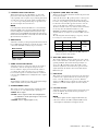
Equalizer Tips
The best advice that can be given regarding equalization while
recording is simply to use as little equalization as possible. If you
want a little more presence you can turn the HIGH end up a bit.
Or you can boost the bass a little if you feel the low end is lack-
ing. During recording it’s better to use EQ sparingly for compen-
sation only.
Cut for a Cleaner Mix
For example: pianos have a lot of energy in the mid and low fre-
quency ranges that you don’t really perceive as musical sound,
but which can interfere with the clarity of other instruments in
these ranges.
You can basically turn the low EQ on piano channels all the way
down without changing the way they sound in the mix. You’ll
hear the difference, however, in the way the mix sounds more
“spacious,” and instruments in the lower ranges will have better
definition.
Naturally you won’t want to do this if the piano is playing solo.
The reverse applies to kick drums and bass guitars: you can often
roll off the high end to create more space in the mix without com-
promising the character of the instruments. You’ll have to use
your ears, though, because each instrument is different and some-
times you’ll want the “snap” of a bass guitar, for example, to
come through.
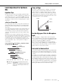
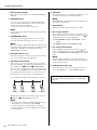
The fundamental and harmonic frequency ranges
of some musical instruments.
Comp settings
One form of compression known as “limiting” can, when prop-
erly used, produce a smooth, unified sound with no excessive
peaks or distortion. A common example of the use of compres-
sion is to “tame” a vocal that has a wide dynamic range in order
to tighten up the mix. Compression can also be applied to guitar
tracks to add extra sustain. Too much compression can be a cause
of feedback, however, so use it sparingly.
Use the High-pass Filter for Microphone
Input
As the name implies, a “high-pass filter” allows only signals
above a certain frequency to pass. Conversely, signals below that
“cutoff frequency” are attenuated. When an MGP high-pass filter
is turned on, signals below 100Hz are attenuated.
This can be useful for minimizing low-frequency breath noise
from a vocalist, as well as handling noise, or rumble transmitted
via the microphone stand. It is generally a good idea to turn the
high-pass filter on for microphone channels.
Start with the Featured Part
You can start working on a mix from almost any part, but it makes
the most sense to start with the main instrument or vocal. Set up
an initial level for the main part, and then build the rest of the mix
around it.
For example, if you’re mixing a piano trio with a vocalist, begin
by setting the level of the vocal track at around the nominal level,
and then gradually add the other instruments. Your choices will
also be influenced by the type of music you are working on. If the
song is a ballad you might want to add the piano to the mix after
the vocal, and then add the bass and drums. If it’s a more rhythmi-
cally oriented piece you could add the bass and drums first, and
then the piano. Whatever best serves the music is right.
Cymbal
Piano
Bass drum
Snare drum
Bass guitar
Guitar
Trombone
Trumpet
20 50 100 200 500 1k 2k 5k 10k 20k (Hz)
Fundamental: The frequency that determines the basic
musical pitch.
Harmonics: Multiples of the fundamental frequency that
play a role in determining the timbre of the
instrument.
Output
0 (Min)
10 (Max)
Input

MGP16X/MGP12X Owner’s Manual
8
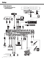
Setup
DI
Powered monitor speakers
CD player
Computer/Audio interface
iPod/
iPhone
Headphones
Synthesizer
Exciter
Portable
recorder
Powered speakers
Powered monitor
speakers (For musician
monitoring)
Effect processor
Microphone x 2
Microphone x 4
Guitar
Drum
Bass
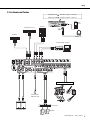
Setup Examples
1. Sound Reinforcement for
Live Performance
(MGP16X) USB : iPod/iPhone signal CH15/16
(MGP12X) USB : iPod/iPhone signal CH11/12

MGP16X/MGP12X Owner’s Manual
9
Setup
iPod/
iPhone
Headphones
Computer/Audio interface
DJ mixer
DVD player (voice)
CD player
Powered speakers
CH8 (for MC)
* MGP12X: CH4
Power amp
Speakers
Instrument, Microphone
2. For Events and Parties
(MGP16X) USB : iPod/iPhone signal CH15/16
(MGP12X) USB : iPod/iPhone signal CH11/12

Setup
MGP16X/MGP12X Owner’s Manual
10
Rack Mounting
The unit requires at least 11U* of rack space. To take into
account the cable connections, we recommend to ensure at least
13U* of rack space.
* 11U corresponds to about 489mm and 13U is about 578mm.
Precautions for Rack Mounting
This unit is rated for operation at ambient temperatures ranging
from 0 to 40 degrees Celsius. If you install this unit along with
other devices in a poorly ventilated rack, the ambient temperature
inside the rack may rise, resulting in inefficient performance.
Be sure to rack-mount in the following conditions so the unit does
not overheat.
• When mounting the unit in a rack with devices such as power
amplifiers that generate a significant amount of heat, leave
more than 1U of space between the MGP and other equipment.
Also either leave the open spaces uncovered or install appropri-
ate ventilating panels to minimize the possibility of heat
buildup.
• To ensure sufficient airflow, leave the rear of the rack open and
position it at least 10 centimeters from walls or other surfaces.
If the rear of the rack cannot be left open, install a commer-
cially available fan or similar ventilating option to secure suffi-
cient airflow. If you’ve installed a fan kit, there may be cases in
which closing the rear of the rack will produce a greater cool-
ing effect. Refer to the rack and/or fan unit manual for details.
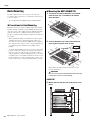
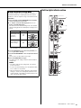
Mounting the MGP16X/MGP12X
1. Two metal rack-mount brackets are screwed
onto the unit. Use a screwdriver to remove
these brackets.
2. Turn the brackets over, and fasten them into
place again using the same screws.
Fasten them to the mixer in order (as shown): q center,
w front, and e back.
CAUTION
Be sure to use the same screws that were removed in step
1. Using other screws can cause damage.
MGP16X
3. Mount the unit into the rack, and fasten it into
place.
w
q
e
w
q
e
11U
13U

MGP16X/MGP12X Owner’s Manual
11
Setup
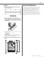
MGP12X
3. Prepare the included rack-mount kit (2 sup-
ports and 6 screws).
4. Use the included screws to fasten the rack-
mount supports with a triangular mark ( ) on
the top side, to the installed rack-mount brack-
ets in step 2.
Fasten them to the mixer in order (as shown): q center, w
front, and e back.
Similarly fasten the other side as well.
CAUTION
Be sure to use the included screws with the MGP12X.
Using other screws can cause damage.
5. Mount the unit into the rack, and fasten it into
place.
Security Cover Mounting
In order to prevent the control knobs of the front panel from being
operated inadvertently, you can attach a protective cover using
four screw holes on the unit. (Size: M3; horizontal spacing:
410mm for MGP16X and 311mm for MGP12X; vertical spacing:
208.5mm.) Yamaha does not sell such a cover; however, you can
easily make one yourself and attach it to the front cover.
When mounting a cover make sure that the screws used do not go
deeper than 12 millimeters into the front panel. Also, to ensure
that the cover does not come in contact with the panel controls,
leave a space of about 20–25 millimeters between the front panel
and the cover.
w
q
e
11U
13U

MGP16X/MGP12X Owner’s Manual
12
Quick Start Guide
We’ll begin this guide by connecting a pair of speakers
and generating some stereo output. Note that the oper-
ations and procedures will vary somewhat according to
the input devices you are using.
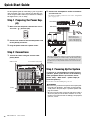
Step 1 Preparing the Power Sup-
ply
1. Make sure that the power switch of the unit is
set to the “ ” position (off).
2. Connect the socket of the included power cord
to the [AC IN] connector.
3. Plug the power cord into a power outlet.
Step 2 Connections
1. Turn all the faders and gain controls com-
pletely down.
2. Connect the microphones and/or instruments
you intend to use.
For details on making connections, refer to the “Setup Exam-
ples” on pages 8, 9.
Step 3 Powering Up the System
To prevent an unwanted burst of noise from the
speakers, power up the devices in the following
order: peripheral devices (instrument, micro-
phone, iPod) MGP mixer power amps (or
powered speakers).
Reverse this order when turning the power off.
CAUTION
• If you are using condenser microphones that require phan-
tom power, turn the mixer’s +48V switch on before turning
on the power to the power amps or powered speakers. See
page 18 for details.
• Be sure to turn the power on/off in the order given in Step 3
above every time you use the device. Failure to do so may
result in loud noise bursts that can damage your equipment,
your ears, or both.
GAIN controls Power switch (rear panel)
Faders
DI
Front Panel
Rear Panel
When using a con-
denser microphone,
set the +48V phantom
switch to ON (page 18).
Although electric guitars and basses can be connected directly
to the mixer’s inputs, the sound is likely to be thin and possibly
noisy. For best results with these types of instruments use a DI
box (direct box) or amp simulator between the instrument and
the mixer.

MGP16X/MGP12X Owner’s Manual
13
Quick Start Guide
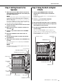
Step 4 Getting Sound to the
Speakers
1. Adjust the channel GAIN controls so that the
corresponding peak indicators flash briefly on
the highest peak levels.
NOTE
To use the level meter to get an accurate reading of the incom-
ing signal level, turn the channel PFL switch on. Adjust the
GAIN controls so that level meter indication occasionally rises
above the “<” (0) level.
Note that the PHONES jack outputs the pre-fader signal from
all channels for which the PFL switch is ON, so that those sig-
nals can be monitored via the headphones.
2. Turn on the ON and ST switches for each chan-
nel you are using.
3. Make sure that all PFL and AFL switches are
set to off ( ).
4. Turn on ( ) the ON switch for the STEREO
master.
5. Raise the STEREO master fader to the “0”
position.
6. Set the channel faders to create the desired
initial balance.
7. Adjust the overall volume of the STEREO mas-
ter fader.
The overall headphone level is adjusted by the MONITOR/
PHONES control.
NOTE
If the PEAK indicator lights frequently, slightly lower the chan-
nel faders to avoid distortion.
Step 5 Using the Built-in Digital
Effects
1. Turn the [PROGRAM] knob to select the
desired effect, and then press the knob to
enable it.
For details about available effects, see the Digital Effect Pro-
gram List on page 28.
2. Turn on ( ) the FX1/FX2 ON button.
The button lights up when it is turned on.
3. Set the FX1/FX2 RTN fader to the “0” position.
4. Use the channel FX1/FX2 controls to adjust the
effect depth for each channel.
5. Use the FX1/FX2 RTN fader to adjust the over-
all effect depth.
You can use the PARAMETER control to adjust effect
parameters such as reverb time and delay time. For details
about the parameters of each effect that can be adjusted with
the PARAMETER control, see page 28.
1
2
1
2
5,7
3
1,7
7
63
4
Level meter
MONITOR PHONES control
GAIN controls
Channel ON
switches
PEAK
indicators
Channel ST
switches
PFL switches Channel faders AFL switches
STEREO master fader
STEREO master ON switch
45
1
3,5
2
PAR AM ETE R
controls
FX1/FX2 controls
FX1/FX2 RTN faders
ON buttons
PROGRAM knobs

Quick Start Guide
MGP16X/MGP12X Owner’s Manual
14
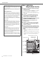
Step 6 <Application>
Using the Ducker function
1. Connect a music player or device for playing
background music.
Connect the device to CH13/14 or CH15/16 on the MGP16X,
and to CH9/10 or CH11/12 on the MGP12X.
To connect an iPod/iPhone, use the USB terminal of the
MGP, and then set to the TO CH15/16 (TO CH11/12) switch
to USB ( ).
2. Turn on ( ) the DUCKER switch for each
channel you are using, and then adjust the
channel’s input to an appropriate level.
3. Connect the microphone to the SOURCE chan-
nel (MGP16X: CH8, MGP12X: CH4).
4. Adjust the input of the microphone to an
appropriate level.
5. Turn on ( ) the ON switch of the SOURCE
channel, and then raise the channel fader to
around “0” (nominal).
6. Play the background music, and listen to con-
firm that the sound volume automatically turns
down when you speak into the microphone.
NOTE
• The volume on the SOURCE channel is detected after fader
adjustment.
It is affected by the setting of ON switch and/or the channel
fader.
• If you want to make custom changes to the automatic sound
attenuation, refer to “About the Detailed Setting Mode” on
page 21.
Built-in digital effects
Your mixes can be further refined by adding ambience effects
such as reverb or delay.
The MGP’s internal effects can be used to add reverb or delay
to individual channels in the same way as external effects pro-
cessors.
Reverb and Delay Time
Small adjustments to the reverb/delay time can actually have a
significant effect on the sound. The optimum reverb time for a
piece of music will depend on the music’s tempo and density,
but as a general rule longer reverb times are good for ballads,
while shorter reverb times are more suited to up-tempo tunes.
Delay times can be adjusted to create a wide variety of
“grooves.” When adding delay to a vocal, for example, try set-
ting the delay time to dotted eighth notes (e.) corresponding to
the tune’s tempo.
Reverb Tone
Different reverb programs will have different “reverb tone” due
to differences in the reverb time of the high or low frequencies.
Too much reverb, particularly in the high frequencies, can
result in unnatural sound and interfere with the high frequen-
cies in other parts of the mix. It’s always a good idea to choose
a reverb program that gives you the depth you want without
detracting from the clarity of the mix.
Reverb Level
It’s amazing how quickly your ears can lose perspective and
fool you into believing that a totally washed-out mix sounds
perfectly fine. To avoid falling into this trap start with reverb
level all the way down, then gradually bring the reverb into the
mix until you can just hear the difference. Any more than this
normally becomes a “special effect.”
You don’t want reverb to dominate the mix unless you are try-
ing to create the effect of a band in a cave-which is a perfectly
legitimate creative goal if that’s the sort of thing you’re aiming
for.
2
1
1
3
5
4
2
5
TO CH15/16 (TO CH11/12) switch
DUCKER switches
GAIN control
ON switch
Channel fader
SOURCE channel
GAIN controls
CH13/14, CH15/16
(CH9/10, CH11/12)

MGP16X/MGP12X Owner’s Manual
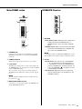
15
Controls and Connectors
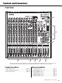
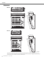
Front Panel
* Throughout this manual, all panel illustrations show the panel of the MGP16X. On the MGP12X, there are four channels in the
mono input section (see 1 below) and 12 channels in the channel I/O connectors section (see 10 on the next page).
Channel Control Block
1. Mono input section ............................................. page 18
2. Mono and stereo input section ........................... page 18
3. Stereo input section............................................ page 18
Master Control Block
4. iPod/iPhone section............................................ page 20
5. Built-in digital effects section .............................. page 21
6. Meter/PHONES section...................................... page 23
7. R E T U R N/2TR IN section.................................... page 23
8. SEND MASTER section ..................................... page 24
9. GROUP/STEREO section .................................. page 24
1 2 3 5 9
8
6
4
7

Controls and Connectors
MGP16X/MGP12X Owner’s Manual
16
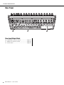
Rear Panel
Rear Input/Output Block
10. Channel I/O connectors section ....................... page 25
11. Master I/O connectors section.......................... page 26
12. Power section................................................... page 26
11 1012

MGP16X/MGP12X Owner’s Manual
17
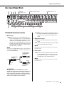
Controls and Connectors
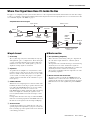
Where Your Signal Goes Once It’s Inside the Box
The purpose of configuring an audio system around a mixer is to collect signals from all channels and mix their levels and other settings
to achieve a good balance. The following simplified mixer block diagram shows how the input signal flows once it’s inside the mixer. For
an overall block diagram of the MGP, see page 33.
Input channel
q Head amp
The very first stage in any mixer, and usually the only stage
with significant “gain” or “amplification.” The head amp has
a “gain” control that adjusts the mixer’s input sensitivity to
match the level of the source. Small signals (e.g. mics) are
amplified, and large signals are attenuated.
w Equalizer
An equalizer boosts (amplifies) or cuts (attenuates) certain
frequency ranges to shape the tone. It can be used to modify
the tone to suit the acoustic characteristics of a room, to make
creative sounds, or for many other purposes. An equalizer
could be a high pass filter that cuts the sound below a speci-
fied frequency.
e PEAK indicator
When the level of an input signal exceeds the level that can be
handled by the mixer’s head amp or equalizer, distortion and
noise will result. The PEAK indicators are used to visually
check the signal level to ensure no overload occurs.
If the PEAK indicator lights continuously, make sure that sig-
nals are not amplified too much by the equalizer, and if
needed, adjust the GAIN control of the head amp to reduce
the level.
It is important to know the mixer stage for which the PEAK
indicators are indicating signal levels. The PEAK indicator of
this unit detects the signal after the head amp and EQ stage.
r Channel fader
A channel fader enables you to adjust the level of the corre-
sponding input channel signal that is going to be routed to the
buses (excluding a pre-fader signal). It is the most often used
control during performance.
Master section
t Bus (Summing Amplifier)
This is where the actual “mixing” takes place. Signals from
all of the mixer’s input channels are “summed” (mixed)
together here.
The signals flow in each channel from top to down after being
adjusted by the level control, and then these signals are
summed (mixed) from left to right. Finally, the overall level is
adjusted by the master control located at far right.
The operation of summing from left to right is the role of the
bus (summing amplifier).
y Master control and level meter
The master controls, specifically, the STEREO fader and
GROUP faders, are the means used to adjust the level of all
signals from all of the mixer’s input channels. The level meter
LED shows the level of the signal flowing to the STEREO
bus.
Simplified Mixer Block Diagram
Input channel Master section
INPUT
HA
EQ
PEAK
CH Fader
SUM
GROUP
Fader
STEREO
Fader
LED meter
OUTPUT
CHs INPUT
q Head amp w Equalizer e PEAK
indicator
r Channel
fader
t Bus y Master control and
level meter

Controls and Connectors
MGP16X/MGP12X Owner’s Manual
18
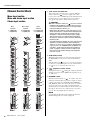
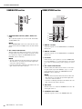
Channel Control Block
Mono input section
Mono and stereo input section
Stereo input section
q +48V switch and indicator
This switch toggles phantom power on and off. When this
switch is turned on ( ), the mixer supplies DC +48V
power to pins 2 and 3 of all XLR input jacks. Turn this switch
on when using one or more phantom-powered condenser
microphones. The indicator lights when it is turned on.
CAUTION
• Be sure to leave this switch off ( ) if you do not need
phantom power. Humming or damage may result if you
connect to an unbalanced device or to an ungrounded
transformer while this switch is on.
• When turning the switch on, make sure that only a con-
denser microphone is connected to the XLR input jacks.
Devices other than condenser microphones may be
damaged if connected to the phantom power supply.
This precaution does not apply to balanced dynamic
microphones, however, as these will not be affected by
phantom power.
• To prevent damage to speakers, be sure to turn off power
amplifiers (or powered speakers) before turning this
switch on or off. It’s also a good idea to turn the mixers
output controls - the STEREO master and GROUP (1-2,
3-4) faders - all the way down when turning phantom
power on. Neglect of these precautions may result in
large noise bursts that may damage your equipment,
your ears, or both.
w 26dB (PAD) switch
When this switch is turned on ( ), the input signal from
the MIC/LINE jack of the mono channel is attenuated by
26dB.
Turn this switch off ( ) if you’ve connected a microphone
or other device with a low input level to the channel. Turn it
on ( ) if you’ve connected a line-level device.
e (High Pass Filter) switch
Turning this switch on ( ) will apply a high-pass filter that
attenuates frequencies below 100Hz in the signal by a slope
of 12dB/octave.
r DUCKER switch
When this switch is turned on ( ), the volume of the stereo
channels is automatically lowered when a signal exceeding a
certain level is input to the SOURCE channel (MGP16X:
CH8, MGP12X: CH4). You can use this switch, for example,
when you want to have the volume of background music
automatically lowered when making an announcement on the
microphone. For effective use of this switch, see Step 6 on
page 14. The switch lights when it is turned on.
NOTE
You can adjust the attenuation of the Ducker function in the
detailed setting mode (see column on page 21).
q
u
o
!0
!2
!5
!7
!6
!1
!3
!8
!5
!7
!6
!8
!5
!7
!6
!8
!4
o
!0
!2
!1
o
t
!0
!2
!1
!3
!4
!3
!4
e
w
y
q
e
y y
r
i
Mono
channels
1–8 (MGP16X),
1–4 (MGP12X)
Mono/stereo
channels
9–12 (MGP16X),
5–8 (MGP12X)
Stereo
channels
13–16 (MGP16X),
9–12 (MGP12X)

MGP16X/MGP12X Owner’s Manual
19
Controls and Connectors
t LEVELER switch and indicator
When playing music from an iPod/iPhone or other audio
players, the actual sound output level may differ for each
song depending on the assigned category. Turning this switch
on ( ) lets you have the volume adjusted automatically to
a certain level, preventing sudden jumps or dips in the level.
The indicator lights when it is turned on.
NOTE
If an audio player other than iPod/iPhone is connected to the
input jacks (LINE) on the rear panel, initially adjust the input
level according to the softest part (lowest level) of the song,
and then turn on the LEVELER switch. Adjust the input level so
that the level meter indication occasionally rises above the “<”
(0) level while the PFL switch is on.
y GAIN control
Adjusts the sensitivity of the input signal. Monaural channels
have a 26dB switch (w) that lets you change the range of this
control. The adjustable sensitivity range is as follows.
Mono channel
Stereo channel
-34dB to +10dB
u COMP control and indicator
Adjusts the amount of compression applied to the channel.
As the knob is turned to the right the compression ratio
increases while the output gain is automatically adjusted
accordingly. The result is smoother, more even dynamics
because louder signals are attenuated while the overall level
is boosted. The COMP indicator will light when the compres-
sor operates.
NOTE
Avoid setting the compression too high, as the higher average
output level that results may lead to feedback.
i STEREO IMAGE switch
This switch selects the output signal by switching the input
stereo signal to one of the following three signal types.
• MONO : Mono signal
• BLEND : Stereo signal in which left and right inputs
are mixed in a certain percentage for a more nat-
ural stereo image.
• STEREO : Stereo signal (original, as is)
o Equalizer (HIGH, MID, and LOW)
This three-band equalizer adjusts the channel’s high, mid, and
low frequency bands.
Setting the knob to the “t” position produces a flat response
in the corresponding band. Turning the knob to the right
boosts the corresponding frequency band, while turning to the
left attenuates the band. The upper knob sets the center fre-
quency for the mid range, while the lower knob sets the
amount of attenuation or boost (counterclockwise/clockwise)
for the range. For the CH9/10 and CH11/12 (on the
MGP16X), and CH5/6 and CH7/8 (on the MGP12X), the
attenuation/boost can only be set at a fixed 2.5kHz center fre-
quency.
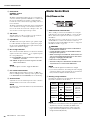
The following table shows the EQ type, frequency, and cut/
boost range for each of the three bands.
* The MID frequency can be adjusted from 250Hz to 5kHz.
The MID frequency is 2.5kHz when the MID frequency
control is set at the center position.
!0 AUX1 PRE, AUX2 controls
These knobs adjust the channel’s signal levels sent to AUX
buses 1 and 2. Each knob controls the signal sent to the corre-
sponding AUX bus. These knobs should generally be set
close to the “t” (nominal) position. The AUX1 control
adjusts the signal before the channel fader (pre-fader). The
signal adjusted by the AUX2 control is determined by the
PRE switch (!1).
!1 PRE switch
This switch selects whether the signal sent to the AUX 2 bus
is taken after the equalizer but before the channel fader (pre-
fader), or after the channel fader (post-fader). When the
switch is on ( ), the mixer sends the pre-fader signal to the
AUX2 bus, so that the AUX2 output is not affected by the
fader.
!2 FX1, FX2 controls
Adjusts the level of the signal (post-fader) sent from the chan-
nel into the FX bus. These knobs should generally be set
close to the “t” position.
NOTE
• To send the signal to the bus engage the ON switch (!4).
• On stereo channels, the LINE L (odd) and LINE R (even)
input signals are mixed before moving into the bus.
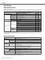
26dB switch Range
ON -34dB to +10dB
OFF -60dB to -16dB
Band Type Frequency
Cut/Boost
range
HIGH Shelving 8kHz
±15dBMID Peaking 2.5kHz*
LOW Shelving 125Hz

Controls and Connectors
MGP16X/MGP12X Owner’s Manual
20
!3 PAN control
PAN/BAL control
BAL control
The PAN control knob determines the stereo positioning of
each mono channel signal in the GROUP 1-2, 3-4 buses or in
the stereo L and R buses. For example, rotating the knob
toward L moves the sound to the left (depending on the loca-
tion of the knob).
The BAL control knob sets the balance between left and right
stereo channels. For example, rotate the knob toward L to
increase the volume level of the left or Groups 1 and 3, and
decrease the level of the right or Groups 2 and 4.
!4 ON switch
Turn this switch on ( ) to send the respective channel’s
signal to the buses. The switch lights when on.
!5 Input Meter
The LEDs indicate the input channel’s post-equalizer signal
level. The SIG indicator lights when a signal is being input
into the channel. The PEAK indicator lights when the input
signal level is 3dB below clipping.
!6 Bus assign switches
These switches determine the bus(es) to which each channel’s
signal is sent. Press the switch in ( ) to output the signal to
the corresponding buses.
• 1-2, 3-4 switches: Assign the channel’s signal to the
GROUP1-2, 3-4 buses.
• ST switch: Assigns the channel’s signal to the STE-
REO L and R buses.
NOTE
To send the signal to each bus, engage the ON switch.
!7 PFL switch and indicator
When the PFL (Pre-Fader Listen) switch is on ( ), the
indicator will light and the channel pre-fader signal is output
to the MONITOR OUT and PHONES jacks for monitoring.
!8 Channel fader
Adjusts the level of the channel signal. Use these controls to
adjust the balance between the various channels.
NOTE
To reduce noise, set the fader sliders for any unused channels
all the way down.
Master Control Block
iPod/iPhone section
q USB connector and indicator
This is a USB port dedicated for iPod/iPhone use. Using the
USB cable that came with the iPod/iPhone, connect the iPod/
iPhone. The indicator lights when the mixer recognizes the
iPod/iPhone.
If the mixer does not recognize the device or if a non-compli-
ant iPod/iPhone is connected, the indicator remains off.
For details on supported iPod/iPhone models, see “Supported
iPod/iPhone models” on page 30.
CAUTION
• Use the genuine Apple Dock Connector USB Cable for
the iPod/iPhone connection.
• Connect the USB connector to the iPod/iPhone before
turning the mixer power on.
• When connecting to an iPod/iPhone, allow at least 6 sec-
onds to pass between turning the mixer on and off and
plugging or unplugging the USB cable.
• Please do not use a USB hub.
• The mixer’s USB port is dedicated for iPod/iPhone use
only. Please do not connect other USB devices.
NOTE
• While the indicator lights, the iPod/iPhone is charged.
• If you connect your iPhone, an incoming call cause a ringing
sound to be output. In order to prevent this, we recommend
that your iPhone’s “Airplane” mode be turned on.
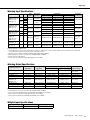
w Routing assign switches
Determine the destination of the input signal. The switch set-
ting and the destination is shown below.
NOTE
• The volume of an iPod/iPhone which was assigned to CH15/
16 (CH11/12) cannot be controlled by the GAIN control.
• Use the detailed setting mode in the column on the next
page to attenuate the playback level from an iPod/iPhone
assigned to CH15/16 (CH11/12).
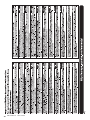
Switch
Switch
Setting
Audio Signal
Input Source
Output Destina-
tion Channels
TO CH15/16
(MGP16X)
TO CH11/12
(MGP12X)
ANALOG
CH15/16 jacks
(MGP16X)
CH11/12 jacks
(MGP12X)
CH15/16
(MGP16X)
Ch11/12
(MGP12X)
USB
iPod/iPhone
TO 2TR IN
ANALOG
2TR IN jacks
2TR IN
USB
iPod/iPhone
qw
Sayfa yükleniyor...
Sayfa yükleniyor...
Sayfa yükleniyor...
Sayfa yükleniyor...
Sayfa yükleniyor...
Sayfa yükleniyor...
Sayfa yükleniyor...
Sayfa yükleniyor...
Sayfa yükleniyor...
Sayfa yükleniyor...
Sayfa yükleniyor...
Sayfa yükleniyor...
Sayfa yükleniyor...
Sayfa yükleniyor...
Sayfa yükleniyor...
Sayfa yükleniyor...
-
 1
1
-
 2
2
-
 3
3
-
 4
4
-
 5
5
-
 6
6
-
 7
7
-
 8
8
-
 9
9
-
 10
10
-
 11
11
-
 12
12
-
 13
13
-
 14
14
-
 15
15
-
 16
16
-
 17
17
-
 18
18
-
 19
19
-
 20
20
-
 21
21
-
 22
22
-
 23
23
-
 24
24
-
 25
25
-
 26
26
-
 27
27
-
 28
28
-
 29
29
-
 30
30
-
 31
31
-
 32
32
-
 33
33
-
 34
34
-
 35
35
-
 36
36


Yamaha MGP12X Kullanım kılavuzu
- Kategori
- Ses mikserleri
- Tip
- Kullanım kılavuzu
- Bu kılavuz aynı zamanda aşağıdakiler için de uygundur:
diğer dillerde
- español: Yamaha MGP12X Manual de usuario
- français: Yamaha MGP12X Manuel utilisateur
- italiano: Yamaha MGP12X Manuale utente
- svenska: Yamaha MGP12X Användarmanual
- čeština: Yamaha MGP12X Uživatelský manuál
- polski: Yamaha MGP12X Instrukcja obsługi
- Deutsch: Yamaha MGP12X Benutzerhandbuch
- português: Yamaha MGP12X Manual do usuário
- English: Yamaha MGP12X User manual
- dansk: Yamaha MGP12X Brugermanual
- русский: Yamaha MGP12X Руководство пользователя
- suomi: Yamaha MGP12X Ohjekirja
- Nederlands: Yamaha MGP12X Handleiding
- română: Yamaha MGP12X Manual de utilizare