Acson 5CEY15E Yükleme Rehberi
- Kategori
- Split sistem klimalar
- Tip
- Yükleme Rehberi

IM-5CEY-0709(1)-ACSON
Part No.: R08019033600A
INSTALLATION MANUAL
INVERTER CEILING/FLOOR
EXPOSED CONVERTIBLE
SPLIT TYPE AIR CONDITIONERS
(E SERIES)
IM-5CEY-0709(1)-COVER_AC(EN).ind1 1IM-5CEY-0709(1)-COVER_AC(EN).ind1 1 3/2/11 5:04:14 PM3/2/11 5:04:14 PM

IM-5CEY-0709(1)-COVER_AC(EN).ind2 2IM-5CEY-0709(1)-COVER_AC(EN).ind2 2 3/2/11 5:04:17 PM3/2/11 5:04:17 PM

English
1-1
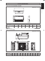
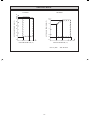
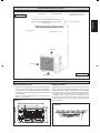
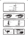
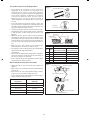
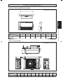
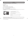
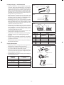
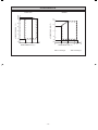
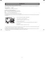
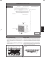
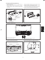
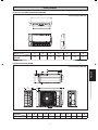
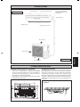
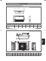
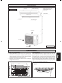
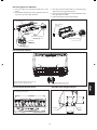
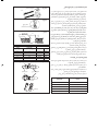
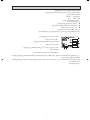
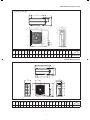
All dimensions are in mm
G
B
DE
C
F
A
Original Instruction
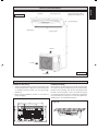
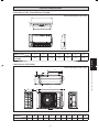
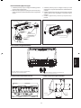
Indoor Unit 5CEY 15/20/25E/ER & 5CEY28ER
OUTLINE AND DIMENSIONS
Dimension
Model
ABCDEFG
5CEY15/20/25E/ER
5CEY28ER
1080 65 630 400 230 218 928
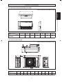
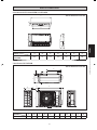
Outdoor Unit 5SLY15D/DR
I
G
H
F
K
J
C
AB
E
D
Dimension
Model
ABCDEFGHI JK
5SLY15D/DR 765 12 550 285 8 311 13 29.5 574 105.5 490
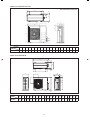
All dimensions are in mm
1 EN 5CEY-0709(1).indd 11 EN 5CEY-0709(1).indd 1 4/20/11 4:36:59 PM4/20/11 4:36:59 PM

1-2
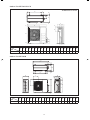
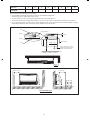
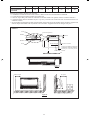
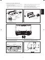
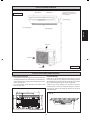
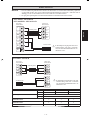
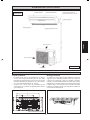
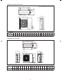
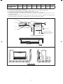
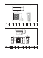
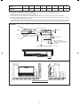
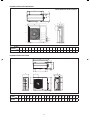
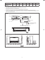
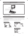
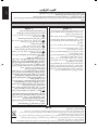
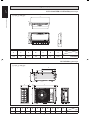
Outdoor Unit 5SLY20C/25C/CR
N
L
KL
TN
M
A
D
O
PBQ
R
S
C
HG
F
E
IJ
All dimensions are in mm
Dimension
Model
ABCDEFGHI JKLMNOPQRST
5SLY20C/25C/CR 855 730 328 513 182 44 93 149 101 113 603 126 164 15 47 3 23 73 75 362
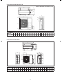
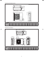
Outdoor Unit 5SLY28CR
A
D
K
E
S
T
S
T
GRR
OMN
H
P
Q
L
C
FU
J
B
I
Dimension
Model
ABCD E FGH I J K LMNO P QR S TU
5SLY28CR
940 348 753 855 392 733 603 328 303 370 362 448 190 80 58 180 32 126 32 15 23
1 EN 5CEY-0709(1).indd 21 EN 5CEY-0709(1).indd 2 4/20/11 4:37:02 PM4/20/11 4:37:02 PM

English
1-3
! WARNING ! CAUTION
•
Installation and maintenance should be performed by qualifi ed
persons who are familiar with local code and regulation, and
experienced with this type of appliance.
•
All fi eld wiring must be installed in accordance with the national
wiring regulation.
•
Ensure that the rated voltage of the unit corresponds to that of the
name plate before commencing wiring work according to the wiring
diagram.
•
The unit must be GROUNDED to prevent possible hazard due to
insulation failure.
•
All electrical wiring must not touch the refrigerant piping, or any
moving parts of the fan motors.
•
Confi rm that the unit has been switched OFF before installing or
servicing the unit.
•
Disconnect from the main power supply before servicing the air
conditioner unit.
•
DO NOT pull out the power cord when the power is ON. This may
cause serious electrical shocks which may result in fi re hazards.
•
Keep the indoor and outdoor units, power cable and transmission
wiring, at least 1m from TVs and radios, to prevent distorted pictures
and static. {Depending on the type and source of the electrical
waves, static may be heard even when more than 1m away}.
Please take note of the following important points when
installing.
Do not install the unit where leakage of fl ammable gas may
occur.
If gas leaks and accumulates around the unit, it may cause
fi re ignition.
Ensure that drainage piping is connected properly.
If the drainage piping is not connected properly, it may cause
water leakage which will dampen the furniture.
Do not overcharge the unit.
This unit is factory pre-charged.
Overcharge will cause over-current or damage to the
compressor.
Ensure that the unitʼs panel is closed after service or
installation.
Unsecured panels will cause the unit to operate noisily.
Sharp edges and coil surfaces are potential locations which may
cause injury hazards.
Avoid from being in contact with these places.
Before turning off the power supply, set the remote controllerʼs
ON/OFF switch to the “OFF” position to prevent the nuisance
tripping of the unit. If this is not done, the unitʼs fans will start
turning automatically when power resumes, posing a hazard to
service personnel or the user.
Do not install the units at or near doorway.
Do not operate any heating apparatus too close to the air
conditioner unit or use in room where mineral oil, oil vapour
or oil steam exist, this may cause plastic part to melt or deform
as a result of excessive heat or chemical reaction.
When the unit is used in kitchen, keep fl our away from going
into suction of the unit.
This unit is not suitable for factory used where cutting oil mist
or iron powder exist or voltage fl uctuates greatly.
Do not install the units at area like hot spring or oil refi nery
plant where sulphide gas exists.
Ensure the color of wires of the outdoor unit and the terminal
markings are same to the indoors respectively.
IMPORTANT: DO NOT INSTALL OR USE THE AIR
CONDITIONER UNIT IN A LAUNDRY ROOM.
Donʼt use joined and twisted wires for incoming power
supply.
Avoid direct contact of any coil treatment cleaners on plastic
part. This may cause plastic part to deform as a result of
chemical reaction.
For any enquiries on spare parts please contact your authorized
dealer.
The equipment is not intended for use in a potentially explosive
atmosphere.
•
•
•
•
•
•
•
•
•
•
•
•
•
•
•
•
•
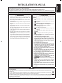
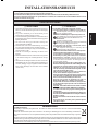
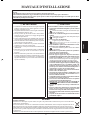
SAFETY PRECAUTIONS
This manual provides the procedures of installation to ensure a safe and good standard of operation for the air conditioner unit.
Special adjustment may be necessary to suit local requirements.
Before using your air conditioner, please read this instruction manual carefully and keep it for future reference.
This appliance is intended to be used by expert or trained users in shops, in light industry and on farms, or for commercial use by lay persons.
INSTALLATION MANUAL
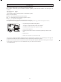
NOTICE
Disposal requirements
Your air conditioning product is marked with this symbol. This means that electrical and electronic products shall not be mixed with unsorted
household waste.
Do not try to dismantle the system yourself: the dismantling of the air conditioning system, treatment of the refrigerant, of oil and of other
parts must be done by a qualifi ed installer in accordance with relevant local and national legislation.
Air conditioners must be treated at a specialized treatment facility for re-use, recycling and recovery. By ensuring this product is disposed
of correctly, you will help to prevent potential negative consequences for the environment and human health. Please contact the installer or
local authority for more information.
Batteries must be removed from the remote controller and disposed of separately in accordance with relevant local and national legislation.
1 EN 5CEY-0709(1).indd 31 EN 5CEY-0709(1).indd 3 4/20/11 4:37:03 PM4/20/11 4:37:03 PM

1-4
IMPORTANT
Important information regarding the refrigerant used
This product contains fl uorinated greenhouse gases covered by the Kyoto Protocol. Do not vent gases into the atmosphere.
Refrigerant type: R410A
GWP
(1)
value: 1975
(1)
GWP = global warming potential
Please fi ll in with indelible ink,
n 1 the factory refrigerant charge of the product,
n 2 the additional refrigerant amount charged in the fi eld and
n 1 + 2 the total refrigerant charge
on the refrigerant charge label supplied with the product.
The fi lled out label must be adhered in the proximity of the product charging port (e.g. onto the inside of the service cover).
1 factory refrigerant charge of the product:
see unit name plate
(2)
2 additional refrigerant amount charged in the fi eld
3 total refrigerant charge
4 contains fl uorinated greenhouse gases covered by the Kyoto Protocol
5 outdoor unit
6 refrigerant cylinder and manifold for charging
(2)
In case of multiple indoor systems, only 1 label must be adhered*, mentioning the total factory refrigerant charge of all
indoor units connected in the refrigerant system.
Periodical inspections for refrigerant leaks may be required depending on European or local legislation. Please contact your
local dealer for more information.
* on the outdoor unit
1 EN 5CEY-0709(1).indd 41 EN 5CEY-0709(1).indd 4 4/20/11 4:37:03 PM4/20/11 4:37:03 PM

English
1-5
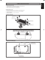
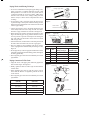
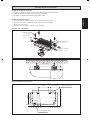
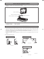
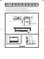
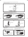
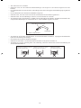
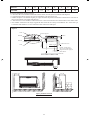
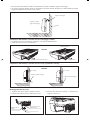
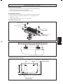
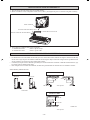
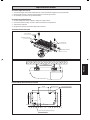
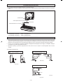
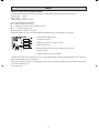
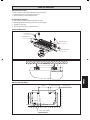
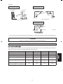
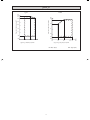
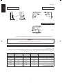
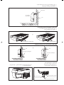
Thermal Insulation
Wrap the Insulated pipe with the
fi nishing tape from bottom to top
Air Discharge Louver
Air Intake Grille
INSTALLATION DIAGRAM
Indoor Unit
Outdoor Unit
Air Intake
Air Intake
Top Panel
Bottom Panel
Air Discharge
Figure A
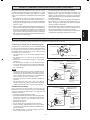
Preliminary Site Survey
• Voltage supply fl uctuation must not exceed ±10% of the
rated voltage. Electricity supply lines must be independent
of welding transformers which can cause high supply
fl uctuation.
• Ensure that the installation location is convenient for
wiring and piping.
Standard Mounting
Ensure that the overhead supports are strong enough to hold
the weight of the unit. Position the hanger rods (wall mounting
bracket for fl oor standing), and check for its alignment with
the unit as shown in Figure A. Also, check that the hangers
are secured and the base of the fan coil unit is leveled in both
horizontal directions, taking into account
the gradient for
drainage fl ow as recommended in Figure B.
A
BC
HG
ED
F
Figure B
10mm or more
All dimensions are in mm
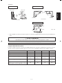
INSTALLATION OF THE INDOOR UNIT
1 EN 5CEY-0709(1).indd 51 EN 5CEY-0709(1).indd 5 4/20/11 4:37:03 PM4/20/11 4:37:03 PM

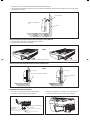
1-6
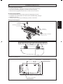
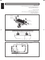
Please ensure that the following steps are taken:
• Unit installation should be fi lted at least 10mm as recommended in Figure B.
• The drain pipe slope shall be kept at least 1:100.
• Provide clearance for easy servicing and optimal air fl ow as shown in Figure C.
• The indoor unit must be installed such that there is no short circuit of the cool discharge air with the warm return air.
• Do not install the indoor unit where there is direct sunlight shining on the unit. The location should be suitable for piping
and drainage installation. The unit must be a large distance away from the door.
400mm or more
250mm or more
1m or more
Floor Standing Type
250mm or more
Dimension A B C D E F G H
5CEY15/20/25E/ER
5CEY28ER
1073 534 268 135 336 630 145 485
Utensils, furnitures or built-in
architectural features must not
protrude more than 250 mm
Drainage Pipe
250mm or less
300mm
(Min.)
500mm or more
10mm
Indoor Unit
Hanger Bracket
Nut
Washer
Washer
Nut
Floor
2300mm or more
Ceiling
Figure C
1 EN 5CEY-0709(1).indd 61 EN 5CEY-0709(1).indd 6 4/20/11 4:37:07 PM4/20/11 4:37:07 PM

English
1-7
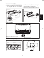
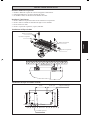
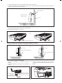
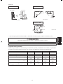
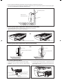
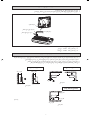
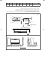
Install the Suspension Bolts
1. Install the suspension bolts so that it can support the indoor unit.
2. Adjust distance to ceiling before installation.
3. Refer to the dimension given to install the unit.
Install the Indoor Units
1. Insert the suspension bolts into the fi ttings of the hanger bracket.
2. Set the nuts and washer on the both side of the metal fi ttings.
3. Secure it with nuts.
4. Attach the hanger cover (4 pcs) to the units.
Suspension Bolt
Hanger Cover
Hanger Cover
Suspension Bolt
Hanger Rod
Installation Floor Standing Type
28mm
479mm
547mm or more
Mounting Bracket
509mm
458mm
301mm or more
759mm or more
Rear Piping Hole
Floor
123mm
78mm
40mm
307mm
Installation Ceiling Type
UNDER CEILING INSTALLATION
1 EN 5CEY-0709(1).indd 71 EN 5CEY-0709(1).indd 7 4/20/11 4:37:07 PM4/20/11 4:37:07 PM

1-8
1. Refer to the dimension as illustrated when installing the mounting bracket.
2. When installing the rear piping, determine the pipe hose position. Drill the pipe hole at the slight downward slant to the
outdoor side.
Mounting Bracket
Wall
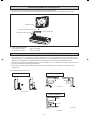
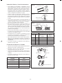
Piping and Drain Hose Installation (Under Ceiling Type)
1. The piping direction can be 2 ways as illustrated.
2. The drain hose is only 1 way.
Rear Piping and Drain Hose Rear Piping Hose
Upper Piping
OR
Hook the unit on the
mounting bracket
Piping and Drain Hose Installation (Floor Standing Type)
Wall
OR
Piping and Drain Hose
Wall
Piping and Drain Hose
How to Install the Drain Hose
1. Remove the two screws and the drain pipe holder.
2. Cut a slit for the drain hose hole.
3. Place the drain hose on the v-shape area and secure it with
drain pipe holder and two screws.
Slit for Drain Hose Hole
Screws
Drain Pipe Holder
1 EN 5CEY-0709(1).indd 81 EN 5CEY-0709(1).indd 8 4/20/11 4:37:08 PM4/20/11 4:37:08 PM

English
1-9
How to Remove Air Inlet Grille
1. Remove the air inlet grille by both hands as the direction
shown.
2. Loosen the screw for fi xing the panel arm (3 screw, left,
right and center). Do not remove the screw at this time.
Air Inlet Grille
Axis of the
Front Panel
Rib
Grille Holder (Center)
(Optional)
Screw
Air Inlet
Grille Holder
Grille Holder (Center)
Grille Holder (L/R)
3. Move the air inlet grille upward, and then turn it backwards.
(Do not use too much force).
4. Remove the grille holder (both left and right side). After
that, remove the air intake grille.
5. Remove the grille holder (center) from the panel.
How to Install the Air Filter
(A)
(A)
(B) (B)
Snap in the fi lter in order to secure it
Install the fi lter to the panel in the (A) direction
follow by (B) to secure the fi lter.
To Adjust the Vane Direction
Adjust the vane linkage as the direction shown to get the
required vane direction
Dimension of the fresh air intake hole
70mm
Ø 3mm
70mm
Ø 64mm
1 EN 5CEY-0709(1).indd 91 EN 5CEY-0709(1).indd 9 4/20/11 4:37:08 PM4/20/11 4:37:08 PM

1-10
1. Knock out the fresh air intake hole at the top panel.
2. Assemble the axial fan, fresh air adapter, fi lter and dust hose as shown in fi gure below.
2" DUCT HOSE
ASSY. FRESH AIR ADAPTER
FILTER FRESH AIR INTAKE
TOP PANEL
3. The axial fan model are as follow.
a. ebm axial fan. 8556A - pin type.
b. ebm axial fan. 8556N - wire type.
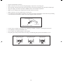
Wall facing one side
More than 50
Side view
Top view
Top view
More than 50 Unit: mm
More than 300
More than 150
More than 150
More than 50
More than 100
More than 50
More than 100
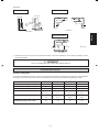
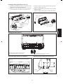
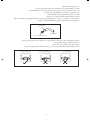
INSTALLATION OF THE OUTDOOR UNIT
INSTALLATION OF FRESH AIR INTAKE
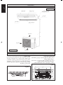
• The outdoor unit must be installed in such a way, so as to prevent short circuit of the hot discharged air or obstruction to
the smooth air fl ow. Please follow the installation clearance shown in the fi gures below. Select the coolest possible place
where intake air temperature is not greater than the outside air temperature.
• Where a wall or other obstacle is in the path of outdoor unitʼs intake or exhaust airfl ow, follow the installation guidelines
below.
• For any of the below installation patterns, the wall height on the exhaust side should be 1200mm or less.
5SLY15D/DR and 5SLY20/25C/CR
Wall facing three sides
Wall facing two sides
1 EN 5CEY-0709(1).indd 101 EN 5CEY-0709(1).indd 10 4/20/11 4:37:08 PM4/20/11 4:37:08 PM

English
1-11
5SLY28CR
More than 100
More than 350
More than 100
More than 350
• Allow more space for installation above with additional obstacle at top side and installation in series.
Unit: mm
Side View
Top View
! CAUTION
• Do not install the unit at altitude over 2000m for both indoor and outdoor
REFRIGERANT PIPING
1200
or less
More
than 100
More than 50
More than 350
More than 50
Top View
More than 50
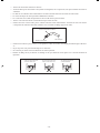
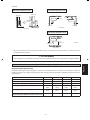
Allowable Piping Length
When the pipe length becomes too long, both the capacity and reliability drop. As a result, compressor reliability will be
affected. Always choose the shortest path and follow the recommendation as tabulated below:
Indoor 5CEY15E/ER 5CEY20/E/ER 5CEY25/E/ER 5CEY28ER
Outdoor 5SLY15D/DR 5SLY20/C/CR 5SLY25/C/CR 5SLY28CR
Max. allowable length, m 15 30 30 50
Max. allowable elevation, m 10 10 10 30
Liquid pipe size, mm/(in) 6.35
(1/4")
6.35
(1/4")
6.35
(1/4")
9.52(
3/8")
Gas pipe size, mm/(in) 12.70
(1/2")
12.70
(1/2")
15.88
(5/8")
15.88
(5/8")
Additional charge of refrigerant, g/m
(for piping length above 7.5m)
20 20 20 50
Wall facing one side Wall facing two sides
Wall facing three sides
1 EN 5CEY-0709(1).indd 111 EN 5CEY-0709(1).indd 11 4/20/11 4:37:09 PM4/20/11 4:37:09 PM

1-12
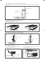
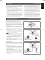
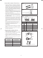
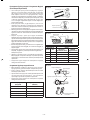
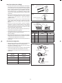
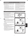
Piping Works And Flaring Technique
Do not use contaminated or damaged copper tubing. If any
piping, evaporator or condenser had been exposed or had
been opened for 15 seconds or more, the system must be
vacuumed. Generally do not remove plastic, rubber plugs
and brass nuts from the valves, fi ttings, tubing and coils
until it is ready to connect suction or liquid line into valves
or fi ttings.
If any brazing work is required, ensure that nitrogen gas
is passed through coil and joints while the brazing work is
being done. This will eliminate soot formation on the inside
wall of copper tubings.
Cut the pipe stages by stages, advancing the blade of pipe
cutter slowly. Extra force and a deep cut will cause more
distortion of pipe and therefore extra burr. See Figure D.
Remove burrs from cut edges of the pipes with remover. See
Figure E. Hold the pipe on top position and burr remover
at lower position to prevent metal chips from entering the
pipe. This will avoid unevenness on the fl are faces which
will cause gas leak.
Insert the fl are nuts, mounted on the connection parts of both
the indoor unit and outdoor unit, into the copper pipes.
The exact length of pipe protruding from the top surface
of the swaging block is determined by the fl aring tool. See
Figure F.
Fix the pipe fi rmly on the swaging block. Match the centers
of both the swaging block and the fl aring punch, then tighten
the fl aring punch fully.
The refrigerant pipe connection are insulated by closed cell
polyurethane.
Piping Connection To The Units
Align the center of the piping and suffi ciently tighten the
fl are nut with fi ngers. See Figure G.
Finally, tighten the fl are nut with torque wrench until the
wrench clicks.
When tightening the fl are nut with the torque wrench,
ensure that the direction for tightening follows the arrow
on the wrench.
The refrigerant pipe connection are insulated by closed cell
polyurethane.
•
•
•
•
•
•
•
•
•
•
•
•
Spanar
Torque Wrench
Indoor Piping
Flare Nut
Flared Tube
Flare Joint
1/4t
Cutting Copper Tube
Copper Tube
Swaging Block
Remove Burr
Copper Tube
Figure E
Figure D
Figure F
Ø Tube, D A (mm)
Inch mm
Imperial
(Wing-nut Type)
Rigid
(Clutch Type)
1/4" 6.35 1.3 0.7
3/8" 9.52 1.6 1.0
1/2" 12.70 1.9 1.3
5/8" 15.88 2.2 1.7
3/4" 19.05 2.5 2.0
Pipe Size,
(mm/in)
Torque,
(Nm/ft-lb)
6.35 (1/4") 18 (13.3)
9.52 (3/8") 42 (31.0)
12.70 (1/2") 55 (40.6)
15.88 (5/8") 65 (48.0)
19.05 (3/4") 78 (57.6)
Figure G
D
A
1 EN 5CEY-0709(1).indd 121 EN 5CEY-0709(1).indd 12 4/20/11 4:37:09 PM4/20/11 4:37:09 PM

English
1-13
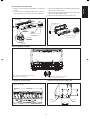
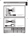
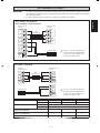
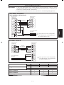
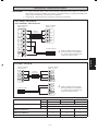
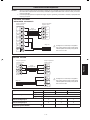
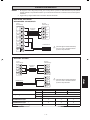
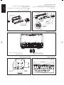
IMPORTANT: * These values are for information only, they should be checked and selected to comply with the local and/or
national codes and regulations. They are also subjected to the type of installation and size of conductors
used.
** The appropriate voltage range should be checked with data label on the unit.
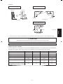
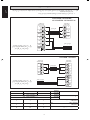
Indoor Unit
Terminal Block
Outdoor Unit
Terminal Block
5CEY15E/ER - 5SLY15D/DR
5CEY20/25E/ER - 5SLY20/25C/CR
Power Supply Cable
L
N
SIG
!
!
2
1
SIG
2
1
!
Interconnection
Cable
!
There must be an all pole disconnection
in the supply mains with a contact
separation of at least 3mm.
ELECTRICAL WIRING CONNECTION
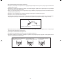
5CEY28ER - 5SLY28CR
Outdoor Unit
Terminal Block
Indoor Unit
Terminal Block
SIG
!
N
L
SIG
N
L
Interconnection
Cable
!
N
L
Model Indoor 5CEY15E/ER 5CEY20/25E/ER 5CEY28ER
Outdoor 5SLY15D/DR 5SLY20/25C/CR 5SLY28CR
Voltage range** Indoor
220V – 240V/1Ph/50Hz + !
Outdoor
220V – 240V/1Ph/50Hz + !
Power supply cable size* mm
2
Number of conductors
1.5
3
2.5
3
2.5
3
Interconnection cable size* mm
2
Number of conductors
1.5
4
2.5
4
1.5
4
Recommended time delay fuse* A 15 20 25
!
Power Supply Cable
!
There must be an all pole disconnection
in the supply mains with a contact
separation of at least 3mm.
1 EN 5CEY-0709(1).indd 131 EN 5CEY-0709(1).indd 13 4/20/11 4:37:10 PM4/20/11 4:37:10 PM

1-14
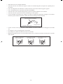
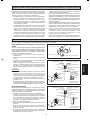
• All wires must be fi rmly connected.
• Make sure all the wire do not touch the refrigerant pipings, compressor or any moving parts.
• The connecting wire between the indoor unit and the outdoor unit must be clamped by using provided cord anchorage.
• The power supply cord must be equivalent to H07RN-F which is the minimum requirement.
• Make sure no external pressure is applied to the terminal connectors and wires.
• Make sure all the covers are properly fi xed to avoid any gap.
• Use round crimp-style terminal for connecting wires to the power supply terminal block. Connect the wires by matching
to the indication on terminal block. (Refer to the wiring diagram attached on the unit).
• Use the correct screwdriver for terminal screws tightening. Unsuitable screwdrivers can damage the screw head.
• Over tightening can damage the terminal screws.
• Do not connect wire of different gauge to same terminal.
• Keep wiring in an orderly manner. Prevent the wiring from obstructing other parts and the terminal box cover.
Attach insulation sleeve
Round crimp-style terminal
Electric wire
Connect wires of the
same gauge to both side.
Do not connect wires of the
same gauge to one side.
Do not connect wires
of different gauges.
1 EN 5CEY-0709(1).indd 141 EN 5CEY-0709(1).indd 14 4/20/11 4:37:10 PM4/20/11 4:37:10 PM

English
1-15
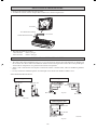
Vacuuming The Piping And The Indoor Unit
Except for the outdoor unit which is pre-charged with
refrigerant, the indoor unit and the refrigerant connection
pipes must be air-purged because the air containing moisture
that remains in the refrigerant cycle may cause malfunction
of the compressor.
Remove the caps from the valve and the service port.
Connect the center of the charging gauge to the vacuum
pump.
Connect the charging gauge to the service port of the
3-way valve.
Start the vacuum pump. Evacuate for approximately
30 minutes. The evacuation time varies with different
vacuum pump capacity. Confi rm that the charging gauge
needle has moved towards -760mmHg.
Caution
If the gauge needle does not move to -760mmHg, be sure
to check for gas leaks (using the refrigerant detector) at
fl are type connection of the indoor and outdoor unit and
repair the leak before proceeding to the next step.
Close the valve of the changing gauge and stop the
vacuum pump.
On the outdoor unit, open the suction valve (3 way) and
liquid valve (2 way) (in anti-clockwise direction) with
4mm key for hexagon sacked screw.
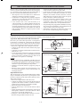
Charge Operation
This operation must be done by using a gas cylinder and a
precise weighing machine. The additional charge is topped-up
into the outdoor unit using the suction valve via the service
port.
Remove the service port cap.
Connect the low pressure side of the charging gauge to
the suction service port center of the cylinder tank and
close the high pressure side of the gauge. Purge the air
from the service hose.
Start the air conditioner unit.
Open the gas cylinder and low pressure charging valve.
When the required refrigerant quantity is pumped into
the unit, close the low pressure side and the gas cylinder
valve.
Disconnect the service hose from service port. Put back
the service port cap.
•
•
•
•
•
•
•
•
•
•
•
•
•
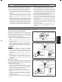
R410A is a new HFC refrigerant which does not damage the
ozone layer. The working pressure of this new refrigerant is
1.6 times higher than conventional refrigerant (R22), thus
proper installation/servicing is essential.
• Never use refrigerant other than R410A in an air
conditioner which designed to operate with R410A.
• Since R410A is a mixed refrigerant, any additional
refrigerant must be charged in liquid state for better
performance compared to in gas state.
• POE or PVE oil is used as lubricant for R410A
compressor, which is different from the mineral oil used
for R22 compressor. During installation or servicing, extra
precaution must betaken not to expose the R410A system
too long to moist air. Residual POE or PVE oil in the piping
and components can absorb moisture from the air.
• To prevent mischarging, the diameter of the service port
on the fl are valve is different from that of R22.
• Use tools and materials exclusively for refrigerant R410A.
Tools exclusively for R410A are manifold valve, charging
hose, pressure gauge, gas leak detector, fl are tools, torque
wrench, vacuum pump and refrigerant cylinder.
• As an R410A air conditioner incurs higher pressure
than R22 units, it is essential to choose the copper pipes
correctly. Never use copper pipes thinner than 0.8mm even
though they are available in the market.
• If the refrigerant gas leakage occurs during installation/
servicing, be sure to ventilate fully. If the refrigerant gas
comes into contact with fi re, a poisonous gas may occur.
• When installing or removing an air conditioner, do not
allow air or moisture to remain in the refrigerant cycle.
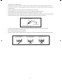
SPECIAL PRECAUTIONS WHEN DEALING WITH R410A UNIT
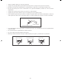
VACUUMING AND CHARGING
Vacuuming is necessary to eliminate all moisture and air from the system.
Refrigerant Piping
Outdoor Unit 3 ways valve
Allen key
Service Port
Flare nut
HIGH PRESSURE GAUGE
GAUGE MANIFOLD
LOW PRESSURE GAUGE
HANDLE HI (ALWAYS CLOSED)
CHARGE HOSE
-760mmHg
HANDLE LO
CHARGE HOSE
VACUUM PUMP
ADAPTER FOR
COUNTER FLOW
PREVENTION
CHECK VALVE
LIQUID VALVE
HIGH PRESSURE GAUGE
LOW PRESSURE GAUGE
GAUGE MANIFOLD
-760mmHg
HANDLE LO
HANDLE HI (ALWAYS CLOSED)
CHARGE HOSE
CHARGE HOSE
CHECK VALVE
LIQUID VALVE
GAS VALVE
(3-WAY)
CONFIGURATION OF AIR
PURGE BY CHARGING
CONFIGURATION OF AIR
PURGE BY CHARGING
GAS VALVE
(3-WAY)
1 EN 5CEY-0709(1).indd 151 EN 5CEY-0709(1).indd 15 4/20/11 4:37:10 PM4/20/11 4:37:10 PM

1-16
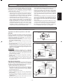
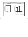
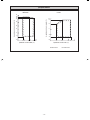
20
18
10
0
-10
-15
-20-20
10 15 20 25 27 30
50
46
43
40
20
30
10
0
-10
10 14 15 19 20 23 25
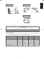
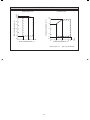
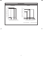
OPERATING RANGE
COOLING HEATING
INDOOR TEMP. WB (˚C) INDOOR TEMP. DB (˚C)
DB: Dry bulb WB: Wet bulb
OUTDOOR TEMP. DB (˚C)
OUTDOOR TEMP. WB(˚C)
1 EN 5CEY-0709(1).indd 161 EN 5CEY-0709(1).indd 16 4/20/11 4:37:11 PM4/20/11 4:37:11 PM

2-1
Français
Toutes les dimensions sont données en mm
G
B
DE
C
F
A
Traduction des instructions dʼorigine
Unité Intérieure 5CEY 15/20/25E/ER & 5CEY28ER
CONTOUR ET DIMENSIONS
Dimension
Modèle
ABCDEFG
5CEY 15/20/25E/ER
5CEY28ER
1080 65 630 400 230 218 928
Unité Extérieure 5SLY 15D/DR
I
G
H
F
K
J
C
AB
E
D
Dimension
Modèle
ABCDEFGHI JK
5SLY15D/DR 765 12 550 285 8 311 13 29,5 574 105,5 490
Toutes les dimensions sont données en mm
2 FR 5CEY-0709(1).indd 12 FR 5CEY-0709(1).indd 1 4/20/11 4:42:48 PM4/20/11 4:42:48 PM

2-2
Unité Extérieure 5SLY20C/25C/CR
N
L
KL
TN
M
A
D
O
PBQ
R
S
C
H
G
F
E
IJ
Toutes les dimensions sont données en mm
Dimension
Modèle
ABCDEFGHI JKLMNOPQRST
5SLY20/25C/CR 855 730 328 513 182 44 93 149 101 113 603 126 164 15 47 3 23 73 75 362
Unité Extérieure 5SLY28CR
A
D
K
E
S
T
S
T
GRR
OMN
H
P
Q
L
C
FU
J
B
I
Dimension
Modèle
ABCD E F GH I J K LMNO P QR S TU
5SLY28CR
940 348 753 855 392 733 603 328 303 370 362 448 190 80 58 180 32 126 32 15 23
2 FR 5CEY-0709(1).indd 22 FR 5CEY-0709(1).indd 2 4/20/11 4:42:51 PM4/20/11 4:42:51 PM
Sayfa yükleniyor...
Sayfa yükleniyor...
Sayfa yükleniyor...
Sayfa yükleniyor...
Sayfa yükleniyor...
Sayfa yükleniyor...
Sayfa yükleniyor...
Sayfa yükleniyor...
Sayfa yükleniyor...
Sayfa yükleniyor...
Sayfa yükleniyor...
Sayfa yükleniyor...
Sayfa yükleniyor...
Sayfa yükleniyor...
Sayfa yükleniyor...
Sayfa yükleniyor...
Sayfa yükleniyor...
Sayfa yükleniyor...
Sayfa yükleniyor...
Sayfa yükleniyor...
Sayfa yükleniyor...
Sayfa yükleniyor...
Sayfa yükleniyor...
Sayfa yükleniyor...
Sayfa yükleniyor...
Sayfa yükleniyor...
Sayfa yükleniyor...
Sayfa yükleniyor...
Sayfa yükleniyor...
Sayfa yükleniyor...
Sayfa yükleniyor...
Sayfa yükleniyor...
Sayfa yükleniyor...
Sayfa yükleniyor...
Sayfa yükleniyor...
Sayfa yükleniyor...
Sayfa yükleniyor...
Sayfa yükleniyor...
Sayfa yükleniyor...
Sayfa yükleniyor...
Sayfa yükleniyor...
Sayfa yükleniyor...
Sayfa yükleniyor...
Sayfa yükleniyor...
Sayfa yükleniyor...
Sayfa yükleniyor...
Sayfa yükleniyor...
Sayfa yükleniyor...
Sayfa yükleniyor...
Sayfa yükleniyor...
Sayfa yükleniyor...
Sayfa yükleniyor...
Sayfa yükleniyor...
Sayfa yükleniyor...
Sayfa yükleniyor...
Sayfa yükleniyor...
Sayfa yükleniyor...
Sayfa yükleniyor...
Sayfa yükleniyor...
Sayfa yükleniyor...
Sayfa yükleniyor...
Sayfa yükleniyor...
Sayfa yükleniyor...
Sayfa yükleniyor...
Sayfa yükleniyor...
Sayfa yükleniyor...
Sayfa yükleniyor...
Sayfa yükleniyor...
Sayfa yükleniyor...
Sayfa yükleniyor...
Sayfa yükleniyor...
Sayfa yükleniyor...
Sayfa yükleniyor...
Sayfa yükleniyor...
Sayfa yükleniyor...
Sayfa yükleniyor...
Sayfa yükleniyor...
Sayfa yükleniyor...
Sayfa yükleniyor...
Sayfa yükleniyor...
Sayfa yükleniyor...
Sayfa yükleniyor...
Sayfa yükleniyor...
Sayfa yükleniyor...
Sayfa yükleniyor...
Sayfa yükleniyor...
Sayfa yükleniyor...
Sayfa yükleniyor...
Sayfa yükleniyor...
Sayfa yükleniyor...
Sayfa yükleniyor...
Sayfa yükleniyor...
Sayfa yükleniyor...
Sayfa yükleniyor...
Sayfa yükleniyor...
Sayfa yükleniyor...
Sayfa yükleniyor...
Sayfa yükleniyor...
Sayfa yükleniyor...
Sayfa yükleniyor...
Sayfa yükleniyor...
Sayfa yükleniyor...
Sayfa yükleniyor...
Sayfa yükleniyor...
Sayfa yükleniyor...
Sayfa yükleniyor...
Sayfa yükleniyor...
Sayfa yükleniyor...
Sayfa yükleniyor...
Sayfa yükleniyor...
Sayfa yükleniyor...
Sayfa yükleniyor...
Sayfa yükleniyor...
Sayfa yükleniyor...
Sayfa yükleniyor...
Sayfa yükleniyor...
Sayfa yükleniyor...
Sayfa yükleniyor...
Sayfa yükleniyor...
Sayfa yükleniyor...
-
 1
1
-
 2
2
-
 3
3
-
 4
4
-
 5
5
-
 6
6
-
 7
7
-
 8
8
-
 9
9
-
 10
10
-
 11
11
-
 12
12
-
 13
13
-
 14
14
-
 15
15
-
 16
16
-
 17
17
-
 18
18
-
 19
19
-
 20
20
-
 21
21
-
 22
22
-
 23
23
-
 24
24
-
 25
25
-
 26
26
-
 27
27
-
 28
28
-
 29
29
-
 30
30
-
 31
31
-
 32
32
-
 33
33
-
 34
34
-
 35
35
-
 36
36
-
 37
37
-
 38
38
-
 39
39
-
 40
40
-
 41
41
-
 42
42
-
 43
43
-
 44
44
-
 45
45
-
 46
46
-
 47
47
-
 48
48
-
 49
49
-
 50
50
-
 51
51
-
 52
52
-
 53
53
-
 54
54
-
 55
55
-
 56
56
-
 57
57
-
 58
58
-
 59
59
-
 60
60
-
 61
61
-
 62
62
-
 63
63
-
 64
64
-
 65
65
-
 66
66
-
 67
67
-
 68
68
-
 69
69
-
 70
70
-
 71
71
-
 72
72
-
 73
73
-
 74
74
-
 75
75
-
 76
76
-
 77
77
-
 78
78
-
 79
79
-
 80
80
-
 81
81
-
 82
82
-
 83
83
-
 84
84
-
 85
85
-
 86
86
-
 87
87
-
 88
88
-
 89
89
-
 90
90
-
 91
91
-
 92
92
-
 93
93
-
 94
94
-
 95
95
-
 96
96
-
 97
97
-
 98
98
-
 99
99
-
 100
100
-
 101
101
-
 102
102
-
 103
103
-
 104
104
-
 105
105
-
 106
106
-
 107
107
-
 108
108
-
 109
109
-
 110
110
-
 111
111
-
 112
112
-
 113
113
-
 114
114
-
 115
115
-
 116
116
-
 117
117
-
 118
118
-
 119
119
-
 120
120
-
 121
121
-
 122
122
-
 123
123
-
 124
124
-
 125
125
-
 126
126
-
 127
127
-
 128
128
-
 129
129
-
 130
130
-
 131
131
-
 132
132
-
 133
133
-
 134
134
-
 135
135
-
 136
136
-
 137
137
-
 138
138
-
 139
139
-
 140
140


Acson 5CEY15E Yükleme Rehberi
- Kategori
- Split sistem klimalar
- Tip
- Yükleme Rehberi
diğer dillerde
- español: Acson 5CEY15E Guía de instalación
- français: Acson 5CEY15E Guide d'installation
- italiano: Acson 5CEY15E Guida d'installazione
- Deutsch: Acson 5CEY15E Installationsanleitung
- English: Acson 5CEY15E Installation guide
- русский: Acson 5CEY15E Инструкция по установке
İlgili makaleler
Diğer belgeler
-
Mitsubishi MSZ-HJ35VA El kitabı
-
McQuay E Series Yükleme Rehberi
-
 Siesta AHQ125CV1 Yükleme Rehberi
-
Sharp AE-A9NR Kullanma talimatları
-
-
-
LG AMNW07GDBR0 Yükleme Rehberi
-
-
Mitsubishi Electric PXZ-4F75VG Split-Type Air-Conditioner Kullanım kılavuzu
-
Samsung AM071KNTDEH/TR Yükleme Rehberi
