
1
ASRock H61iCafe Motherboard
English
Copyright Notice:
No part of this installation guide may be reproduced, transcribed, transmitted, or trans-
lated in any language, in any form or by any means, except duplication of documentation
by the purchaser for backup purpose, without written consent of ASRock Inc.
Products and corporate names appearing in this guide may or may not be registered
trademarks or copyrights of their respective companies, and are used only for identifi ca-
tion or explanation and to the owners’ benefi t, without intent to infringe.
Disclaimer:
Specifi cations and information contained in this guide are furnished for informational use
only and subject to change without notice, and should not be constructed as a commit-
ment by ASRock. ASRock assumes no responsibility for any errors or omissions that may
appear in this guide.
With respect to the contents of this guide, ASRock does not provide warranty of any kind,
either expressed or implied, including but not limited to the implied warranties or condi-
tions of merchantability or fi tness for a particular purpose. In no event shall ASRock, its
directors, offi cers, employees, or agents be liable for any indirect, special, incidental, or
consequential damages (including damages for loss of profi ts, loss of business, loss of
data, interruption of business and the like), even if ASRock has been advised of the pos-
sibility of such damages arising from any defect or error in the guide or product.
This device complies with Part 15 of the FCC Rules. Operation is subject to the following
two conditions:
(1) this device may not cause harmful interference, and
(2) this device must accept any interference received, including interference that
may cause undesired operation.
CALIFORNIA, USA ONLY
The Lithium battery adopted on this motherboard contains Perchlorate, a toxic substance
controlled in Perchlorate Best Management Practices (BMP) regulations passed by the
California Legislature. When you discard the Lithium battery in California, USA, please
follow the related regulations in advance.
“Perchlorate Material-special handling may apply, see
www.dtsc.ca.gov/hazardouswaste/perchlorate”
ASRock Website: http://www.asrock.com
Published February 2011
Copyright
©
2011 ASRock INC. All rights reserved.

2
ASRock H61iCafe Motherboard
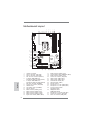
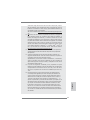
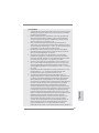
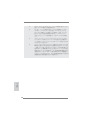
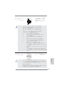
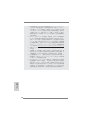
Motherboard Layout
English
1 1155-Pin CPU Socket 17 SATA2 Connector (SATA2_3, Blue)
2 CPU Fan Connector (CPU_FAN1) 18 Chassis Speaker Header (SPEAKER 1, White)
3 CPU Fan Connector (CPU_FAN2) 19 SATA2 Connector (SATA2_1, Blue)
4 ATX 12V Power Connector (ATX12V1) 20 Chassis Fan Connector (CHA_FAN1)
5 2 x 240-pin DDR3 DIMM Slots 21 USB 2.0 Header (USB8_9, Blue)
(Dual Channel: DDR3_A1, DDR3_B1, Blue) 22 USB 2.0 Header (USB6_7, Blue)
6 2 x 240-pin DDR3 DIMM Slots 23 Infrared Module Header (IR1)
(Dual Channel: DDR3_A2, DDR3_B2, White) 24 COM Port Header (COM1)
7 ATX Power Connector (ATXPWR1) 25 PCI Slots (PCI1-2)
8 Chassis Fan Connector (CHA_FAN2) 26 PCI Express 2.0 x1 Slot (PCIE3, White)
9 32Mb SPI Flash 27 PCI Express 2.0 x1 Slot (PCIE2, White)
10 Clear CMOS Jumper (CLRCMOS1) 28 Front Panel Audio Header
11 Intel H61 Chipset (HD_AUDIO1, White)
12 SATA2 Connector (SATA2_0, Blue) 29 HDMI_SPDIF Header
13 SATA2 Connector (SATA2_2, Blue) (HDMI_SPDIF1, White)
14 SATA3 Connector (SATA3_1, White) 30 PCI Express 2.0 x16 Slot (PCIE1, Blue)
15 SATA3 Connector (SATA3_2, White) 31 Chassis Fan Connector (CHA_FAN3)
16 System Panel Header (PANEL1, White) 32 Power Fan Connector (PWR_FAN1)
Intel
H61
CMOS
Battery
ATXPWR1
DDR3_A1 (64 bit, 240-pin module)
DDR3_A2 (64 bit, 240-pin module)
DDR3_B1 (64 bit, 240-pin module)
DDR3_B2 (64 bit, 240-pin module)
H61iCafe
32Mb
BIOS
PCIE1
PCIE2
PCIE3
PCI1
PCI2
Super
I/O
RoHS
ATX12V1
PCI Express 2.0
21.8cm (8.6 in)
30.5cm (12.0 in)
ErP/EuP Ready
USB6_7
11
11
USB8_9
SPEAKER1
1
IR1
1
HD_AUDIO1
1
HDLED RESET
PLED PWRBTN
PANE L1
1
COM1
1
CLRCMOS1
1
SATA2_2
SATA3_1
SATA2_3
SATA3_2
SATA2_0
SATA2_1
Dual Channel DDR3
CPU_FAN1
CPU_FAN2
CHA_FAN1
CHA_FAN3
PWR_FAN1
CHA_FAN2
USB 2.0
T: U SB 0
B: USB1
PS2
Keyboard
VGA1
DVI_CON1
HDMI1
USB 2.0
T: USB4
B: USB5
Top:
RJ-45
Top:
CTR BASS
Center:
REAR SPK
Bottom:
Optical
SPDIF
Top:
LINE IN
Center:
FRONT
Bottom:
MIC IN
USB 3.0
T:USB2
B: USB3
LAN
PHY
AUDIO
CODEC
HDMI_SPDIF_1
1
Designed in Taipei
DX10.1
1
2
3
4
5
6
7
8
9
10
11
12
13
14
15
16
17
181920
2124
25
23
22
26
27
28
29
30
31
32

3
ASRock H61iCafe Motherboard
English
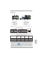
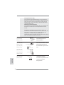
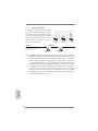
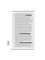
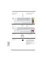
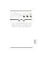
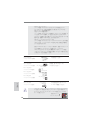
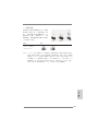
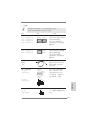
I/O Panel
1 USB 2.0 Ports (USB01) ** 8 Front Speaker (Lime)
2 VGA/D-Sub Port 9 Microphone (Pink)
* 3 LAN RJ-45 Port 10 USB 2.0 Ports (USB45)
4 Central / Bass (Orange) 11 USB 3.0 Ports (USB23)
5 Rear Speaker (Black) 12 VGA/HDMI Port
6 Optical SPDIF Out Port 13 VGA/DVI-D Port
7 Line In (Light Blue) 14 PS/2 Keyboard Port (Purple)
1
2
5
3
6
7
8
9
10
11
13
14
12
4
**
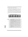
If you use 2-channel speaker, please connect the speaker’s plug into “Front Speaker Jack”.
See the table below for connection details in accordance with the type of speaker you use.
TABLE for Audio Output Connection
Audio Output Channels Front Speaker Rear Speaker Central / Bass Line In or
(No. 8) (No. 5) (No. 4) Side Speaker
(No. 7)
2 V -- -- --
4 V V -- --
6 V V V --
8 V V V V
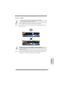
* There are two LED next to the LAN port. Please refer to the table below for the LAN port LED
indications.
LAN Port LED Indications
Activity/Link LED SPEED LED
Status Description Status Description
Off No Link Off 10Mbps connection
Blinking Data Activity Orange 100Mbps connection
On Link Green 1Gbps connection
ACT/LINK
LED
SPEED
LED
LAN Port
To enable Multi-Streaming function, you need to connect a front panel audio cable to the front
panel audio header. After restarting your computer, you will fi nd “Mixer” tool on your system.
Please select “Mixer ToolBox” , click “Enable playback multi-streaming”, and click
“ok”. Choose “2CH”, “4CH”, “6CH”, or “8CH” and then you are allowed to select “Realtek HDA
Primary output” to use Rear Speaker, Central/Bass, and Front Speaker, or select “Realtek
HDA Audio 2nd output” to use front panel audio.

4
ASRock H61iCafe Motherboard
1. Introduction
Thank you for purchasing ASRock H61iCafe motherboard, a reliable motherboard
produced under ASRock’s consistently stringent quality control. It delivers excellent
performance with robust design conforming to ASRock’s commitment to quality and
endurance.
This Quick Installation Guide contains introduction of the motherboard and step-by-
step installation guide. More detailed information of the motherboard can be found
in the user manual presented in the Support CD.
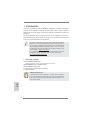
Because the motherboard specifi cations and the BIOS software might be
updated, the content of this manual will be subject to change without no-
tice. In case any modifi cations of this manual occur, the updated version
will be available on ASRock website without further notice. You may fi nd
the latest VGA cards and CPU support lists on ASRock website as well.
ASRock website http://www.asrock.com
If you require technical support related to this motherboard, please visit
our website for specifi c information about the model you are using.
www.asrock.com/support/index.asp
1.1 Package Contents
ASRock H61iCafe Motherboard
(ATX Form Factor: 12.0-in x 8.6-in, 30.5 cm x 21.8 cm)
ASRock H61iCafe Quick Installation Guide
ASRock H61iCafe Support CD
2 x Serial ATA (SATA) Data Cables (Optional)
1 x I/O Panel Shield
ASRock Reminds You...
To get better performance in Windows
®
7 / 7 64-bit / Vista
TM
/ Vista
TM
64-
bit, it is recommended to set the BIOS option in Storage Confi guration to
AHCI mode. For the BIOS setup, please refer to the “User Manual” in our
support CD for details.
English

5
ASRock H61iCafe Motherboard
English
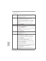
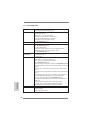
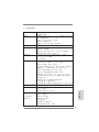
1.2 Specifications
Platform - ATX Form Factor: 12.0-in x 8.6-in, 30.5 cm x 21.8 cm
- All Solid Capacitor design
CPU - Supports 2nd Generation Intel
®
Core
TM
i7 / i5 / i3 in
LGA1155 Package
- 4 + 1 Power Phase Design
- Supports Intel
®
Turbo Boost 2.0 Technology
- Supports K-Series unlocked CPU
- Supports Hyper-Threading Technology (see CAUTION 1)
Chipset - Intel
®
H61
Memory - Dual Channel DDR3 Memory Technology (see CAUTION 2)
- 4 x DDR3 DIMM slots
- Supports DDR3 1333/1066 non-ECC, un-buffered
memory
- Max. capacity of system memory: 16GB (see CAUTION 3)
Expansion Slot - 1 x PCI Express 2.0 x16 slot (blue @ x16 mode)
- 2 x PCI Express 2.0 x1 slots
- 2 x PCI slots
Graphics - Intel
®
HD Graphics 2000/3000
- Pixel Shader 4.1, DirectX 10.1
- Max. shared memory 1759MB (see CAUTION 4)
- Three VGA Output options: D-Sub, DVI-D and HDMI
(see CAUTION 5)
- Supports HDMI 1.4a Technology with max. resolution up to
1920x1200 @ 60Hz
- Supports DVI with max. resolution up to 1920x1200 @ 60Hz
- Supports D-Sub with max. resolution up to 2048x1536 @
75Hz
- Supports Auto Lip Sync, Deep Color (12bpc), xvYCC and
HBR (High Bit Rate Audio) with HDMI
(Compliant HDMI monitor is required) (see CAUTION 6)
- Supports Blu-ray Stereoscopic 3D with HDMI 1.4a
- Supports HDCP function with DVI and HDMI ports
- Supports Full HD 1080p Blu-ray (BD) / HD-DVD playback
with DVI and HDMI ports
Audio - 7.1 CH HD Audio (Realtek ALC887 Audio Codec)
LAN - PCIE x1 Gigabit LAN 10/100/1000 Mb/s
- Atheros
®
AR8151
- Supports Wake-On-LAN

6
ASRock H61iCafe Motherboard
English
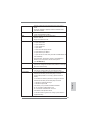
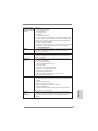
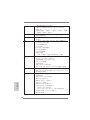
Rear Panel I/O I/O Panel
- 1 x PS/2 Keyboard Port
- 1 x VGA/D-Sub Port
- 1 x VGA/DVI-D Port
- 1 x HDMI Port
- 1 x Optical SPDIF Out Port
- 4 x Ready-to-Use USB 2.0 Ports
- 2 x Ready-to-Use USB 3.0 Ports
- 1 x RJ-45 LAN Port with LED (ACT/LINK LED and SPEED
LED)
- HD Audio Jack: Rear Speaker/Central/Bass/Line in/Front
Speaker/Microphone (see CAUTION 7)
SATA3 - 2 x SATA3 6.0 Gb/s connectors by ASMedia ASM1061,
support NCQ, AHCI and "Hot Plug" functions
USB3.0 - 2 x USB 3.0 ports by ASMedia ASM1042, support
USB 1.0/2.0/3.0 up to 5Gb/s
Connector - 4 x SATA2 3.0 Gb/s connectors, support NCQ, AHCI and
Hot Plug functions
- 2 x SATA3 6.0Gb/s connectors
- 1 x IR header
- 1 x COM port header
- 1 x HDMI_SPDIF header
- CPU/Chassis/Power FAN connector
- 24 pin ATX power connector
- 8 pin 12V power connector
- Front panel audio connector
- 2 x USB 2.0 headers (support 4 USB 2.0 ports)
BIOS Feature - 32Mb AMI BIOS
- AMI UEFI Legal BIOS with GUI support
- Supports “Plug and Play”
- ACPI 1.1 Compliance Wake Up Events
- Supports jumperfree
- SMBIOS 2.3.1 Support
- IGPU, DRAM, PCH, CPU PLL, VTT, VCCSA Voltage
Multi-adjustment
Support CD - Drivers, Utilities, AntiVirus Software (Trial Version), ASRock
Software Suite (CyberLink DVD Suite - OEM and Trial;
Creative Sound Blaster X-Fi MB - Trial)
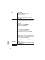
Unique Feature - ASRock Extreme Tuning Utility (AXTU) (see CAUTION 8)
- Instant Boot
- ASRock Instant Flash (see CAUTION 9)
- ASRock AIWI (see CAUTION 10)

7
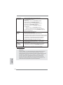
ASRock H61iCafe Motherboard
English
- ASRock APP Charger (see CAUTION 11)
- SmartView (see CAUTION 12)
- ASRock XFast USB (see CAUTION 13)
- Hybrid Booster:
- ASRock U-COP (see CAUTION 14)
- Boot Failure Guard (B.F.G.)
- Combo Cooler Option (C.C.O.) (see CAUTION 15)
- Good Night LED
Hardware - CPU Temperature Sensing
Monitor - Chassis Temperature Sensing
- CPU/Chassis/Power Fan Tachometer
- CPU/Chassis Quiet Fan (Allow Chassis Fan Speed
Auto-Adjust by CPU Temperature)
- CPU/Chassis Fan Multi-Speed Control
- Voltage Monitoring: +12V, +5V, +3.3V, CPU Vcore
OS - Microsoft
®
Windows
®
7 / 7 64-bit / Vista
TM
/ Vista
TM
64-bit
/ XP / XP 64-bit compliant
Certifi cations - FCC, CE, WHQL
- ErP/EuP Ready (ErP/EuP ready power supply is required)
(see CAUTION 16)
* For detailed product information, please visit our website: http://www.asrock.com
WARNING
Please realize that there is a certain risk involved with overclocking, including
adjusting the setting in the BIOS, applying Untied Overclocking Technology, or
using the third-party overclocking tools. Overclocking may affect your system
stability, or even cause damage to the components and devices of your system.
It should be done at your own risk and expense. We are not responsible for possible
damage caused by overclocking.

8
ASRock H61iCafe Motherboard
English
CAUTION!
1. About the setting of “Hyper Threading Technology”, please check page
42 of “User Manual” in the support CD.
2. This motherboard supports Dual Channel Memory Technology. Before
you implement Dual Channel Memory Technology, make sure to read the
installation guide of memory modules on page 14 for proper installation.
3. Due to the operating system limitation, the actual memory size may be
less than 4GB for the reservation for system usage under Windows
®
7 /
Vista
TM
/ XP. For Windows
®
OS with 64-bit CPU, there is no such limita-
tion.
4. The maximum shared memory size is defi ned by the chipset vendor and
is subject to change. Please check Intel
®
website for the latest informa-
tion.
5. You can choose to use two of the four monitors only. D-Sub, DVI-D and
HDMI monitors cannot be enabled at the same time. Besides, with the
DVI-to-HDMI adapter, the DVI-D port can support the same features as
HDMIport.
6. xvYCC and Deep Color are only supported under Windows
®
7 64-bit /
7. Deep Color mode will be enabled only if the display supports 12bpc
in EDID. HBR is supported under Windows
®
7 64-bit / 7 / Vista
TM
64-bit /
Vista
TM
.
7. For microphone input, this motherboard supports both stereo and mono
modes. For audio output, this motherboard supports 2-channel, 4-chan-
nel, 6-channel, and 8-channel modes. Please check the table on page 3
for proper connection.
8. ASRock Extreme Tuning Utility (AXTU) is an all-in-one tool to fi ne-tune
different system functions in a user-friendly interface, which is including
Hardware Monitor, Fan Control, Overclocking, OC DNA and IES. In
Hardware Monitor, it shows the major readings of your system. In Fan
Control, it shows the fan speed and temperature for you to adjust. In
Overclocking, you are allowed to overclock CPU frequency for optimal
system performance. In OC DNA, you can save your OC settings as a
profi le and share with your friends. Your friends then can load the OC
profi le to their own system to get the same OC settings. In IES (Intelligent
Energy Saver), the voltage regulator can reduce the number of output
phases to improve effi ciency when the CPU cores are idle without
sacrificing computing performance. Please visit our website for the
operation procedures of ASRock Extreme Tuning Utility (AXTU).
ASRock website: http://www.asrock.com
9. ASRock Instant Flash is a BIOS fl ash utility embedded in Flash ROM.
This convenient BIOS update tool allows you to update system BIOS
without entering operating systems fi rst like MS-DOS or Windows
®
. With
this utility, you can press <F6> key during the POST or press <F2> key to
BIOS setup menu to access ASRock Instant Flash. Just launch this tool
and save the new BIOS fi le to your USB fl ash drive, fl oppy disk or hard

9
ASRock H61iCafe Motherboard
English
drive, then you can update your BIOS only in a few clicks without prepar-
ing an additional fl oppy diskette or other complicated fl ash utility. Please
be noted that the USB fl ash drive or hard drive must use FAT32/16/12 fi le
system.
10. To experience intuitive motion controlled games is no longer only avail-
able at Wii. ASRock AIWI utility introduces a new way of PC gaming
operation. ASRock AIWI is the world's fi rst utility to turn your iPhone/iPod
touch as a game joystick to control your PC games. All you have to do is
just to install the ASRock AIWI utility either from ASRock offi cial website
or ASRock software support CD to your motherboard, and also download
the free AIWI Lite from App store to your iPhone/iPod touch. Connecting
your PC and apple devices via Bluetooth or WiFi networks, then you can
start experiencing the exciting motion controlled games. Also, please do
not forget to pay attention to ASRock offi cial website regularly, we will
continuously provide you the most up-do-date supported games!
ASRock website: http://www.asrock.com/Feature/Aiwi/index.asp
11. If you desire a faster, less restricted way of charging your Apple devices,
such as iPhone/iPod/iPad Touch, ASRock has prepared a wonderful
solution for you - ASRock APP Charger. Simply installing the APP Char-
ger driver, it makes your iPhone charged much quickly from your com-
puter and up to 40% faster than before. ASRock APP Charger allows you
to quickly charge many Apple devices simultaneously and even supports
continuous charging when your PC enters into Standby mode (S1), Sus-
pend to RAM (S3), hibernation mode (S4) or power off (S5). With APP
Charger driver installed, you can easily enjoy the marvelous charging
experience than ever.
ASRock website: http://www.asrock.com/Feature/AppCharger/index.asp
12.
SmartView, a new function of internet browser, is the smart start page for
IE that combines your most visited web sites, your history, your Facebook
friends and your real-time newsfeed into an enhanced view for a more
personal Internet experience. ASRock motherboards are exclusively
equipped with the SmartView utility that helps you keep in touch with
friends on-the-go. To use SmartView feature, please make sure your
OS version is Windows
®
7 / 7 64 bit / Vista
TM
/ Vista
TM
64 bit, and your
browser version is IE8. ASRock website: http://www.asrock.com/Feature/
SmartView/index.asp
13. ASRock XFast USB can boost USB storage device performance. The
performance may depend on the property of the device.
14. While CPU overheat is detected, the system will automatically shutdown.
Before you resume the system, please check if the CPU fan on the
motherboard functions properly and unplug the power cord, then plug it
back again. To improve heat dissipation, remember to spray thermal
grease between the CPU and the heatsink when you install the PC sys-
tem.

10
ASRock H61iCafe Motherboard
English
15. Combo Cooler Option (C.C.O.) provides the fl exible option to adopt three
different CPU cooler types, Socket LGA 775, LGA 1155 and LGA 1156.
Please be noticed that not all the 775 and 1156 CPU Fan can be used.
16. EuP, stands for Energy Using Product, was a provision regulated by Eu-
ropean Union to defi ne the power consumption for the completed system.
According to EuP, the total AC power of the completed system shall be
under 1.00W in off mode condition. To meet EuP standard, an EuP ready
motherboard and an EuP ready power supply are required. According to
Intel’s suggestion, the EuP ready power supply must meet the standard
of 5v standby power effi ciency is higher than 50% under 100 mA current
consumption. For EuP ready power supply selection, we recommend you
checking with the power supply manufacturer for more details.

11
ASRock H61iCafe Motherboard
English
2. Installation
Pre-installation Precautions
Take note of the following precautions before you install mother-
board components or change any motherboard settings.
1. Unplug the power cord from the wall socket before touching any
component. Failure to do so may cause severe damage to the
motherboard, peripherals, and/or components.
2. To avoid damaging the motherboard components due to static
electricity, NEVER place your motherboard directly on the car-
pet or the like. Also remember to use a grounded wrist strap or
touch a safety grounded object before you handle components.
3. Hold components by the edges and do not touch the ICs.
4. Whenever you uninstall any component, place it on a grounded
antstatic pad or in the bag that comes with the component.
5. When placing screws into the screw holes to secure the moth-
erboard to the chassis, please do not over-tighten the screws!
Doing so may damage the motherboard.
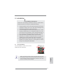
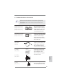
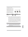
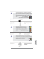
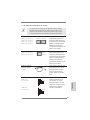
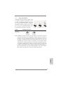
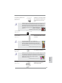
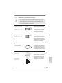
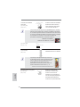
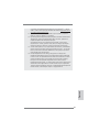
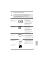
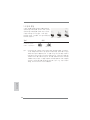
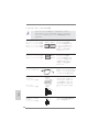
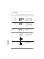
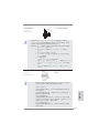
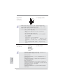
2.1 CPU Installation
For the installation of Intel 1155-Pin CPU,
please follow the steps below.
Before you insert the 1155-Pin CPU into the socket, please check if the
CPU surface is unclean or if there is any bent pin on the socket. Do not
force to insert the CPU into the socket if above situation is found. Other-
wise, the CPU will be seriously damaged.
1155-Pin Socket Overview
Contact Array
Socket Body
Load Lever
Load Plate

12
ASRock H61iCafe Motherboard
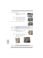
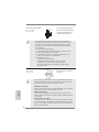
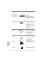
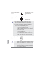
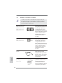
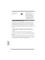
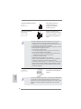
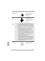
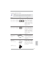
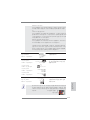
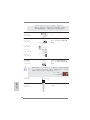
Step 1. Open the socket:
Step 1-1. Disengaging the lever by depressing
down and out on the hook to clear
retention tab.
Step 1-2. Rotate the load lever to fully open po-
sition at approximately 135 degrees.
Step 1-3. Rotate the load plate to fully open po-
sition at approximately 100 degrees.
Step 2. Remove PnP Cap (Pick and Place Cap).
1. It is recommended to use the cap tab to handle and avoid kicking
off the PnP cap.
2. This cap must be placed if returning the motherboard for after
service.
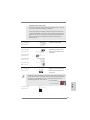
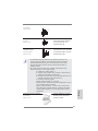
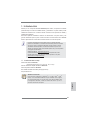
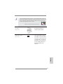
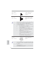
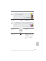
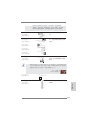
Step 3. Insert the 1155-Pin CPU:
Step 3-1. Hold the CPU by the edges where
are marked with black lines.
Step 3-2. Orient the CPU with IHS (Integrated
Heat Sink) up. Locate Pin1 and the
two orientation key notches.
For proper inserting, please ensure to match the two orientation key
notches of the CPU with the two alignment keys of the socket.
black line
Pin1
alignment key
alignment key
Pin1
1155-Pin CPU
1155-Pin Socket
orientation key notch
orientation key notch
English

13
ASRock H61iCafe Motherboard
English
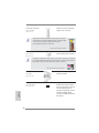
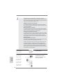
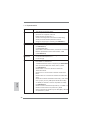
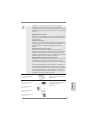
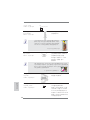
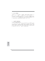
Step 3-3. Carefully place the CPU into the
socket by using a purely vertical mo-
tion.
Step 3-4. Verify that the CPU is within the sock-
et and properly mated to the orient
keys.
Step 4. Close the socket:
Step 4-1. Rotate the load plate onto the IHS.
Step 4-2. While pressing down lightly on load
plate, engage the load lever.
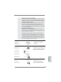
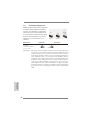
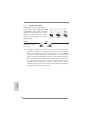
2.2 Installation of CPU Fan and Heatsink
For proper installation, please kindly refer to the instruction manuals of your CPU
fan and heatsink.
Below is an example to illustrate the installation of the heatsink for 1155-Pin CPU.
Step 1. Apply thermal interface material onto center of
IHS on the socket surface.
Step 2. Place the heatsink onto the socket. Ensure
fan cables are oriented on side closest to the
CPU fan connector on the motherboard (CPU_
FAN1, see page 2, No. 2).
Step 3. Align fasteners with the motherboard through-
holes.
Step 4. Rotate the fastener clockwise, then press
down on fastener caps with thumb to install
and lock. Repeat with remaining fasteners.
If you press down the fasteners without rotating them clockwise, the
heatsink cannot be secured on the motherboard.
Step 5. Connect fan header with the CPU fan connector on the motherboard.
Step 6. Secure excess cable with tie-wrap to ensure cable does not interfere with
fan operation or contact other components.
Apply Thermal
Interface Material
Fan cables on side
closest to MB header
Fastener slots
pointing straight out
Press Down
(4 Places)
Please be noticed that this motherboard supports Combo Cooler
Option (C.C.O.), which provides the fl exible option to adopt three dif-
ferent CPU cooler types, Socket LGA 775, LGA 1155 and LGA 1156.
The white throughholes are for Socket LGA
1155/1156 CPU fan.

14
ASRock H61iCafe Motherboard
English
2.3 Installation of Memory Modules (DIMM)
This motherboard provides four 240-pin DDR3 (Double Data Rate 3) DIMM
slots, and supports Dual Channel Memory Technology. For dual channel con g-
uration, you always need to install identical (the same brand, speed, size and
chip-type) DDR3 DIMM pair in the slots of the same color. In other words, you
have to install identical DDR3 DIMM pair in Dual Channel A (DDR3_A1 and
DDR3_B1; Blue slots; see p.2 No.5), so that Dual Channel Memory Technology
can be activated. This motherboard also allows you to install four DDR3 DIMMs
for dual channel con guration, and please install identical DDR3 DIMMs in all
four slots. You may refer to the Dual Channel Memory Con guration Table be-
low.
Dual Channel Memory Confi gurations
DDR3_A1 DDR3_A2 DDR3_B1 DDR3_B2
(Blue Slot) (White Slot) (Blue Slot) (White Slot)
(1) Populated - Populated -
(2)* Populated Populated Populated Populated
1. If you want to install two memory modules, for optimal compatibility
and reliability, it is recommended to install them in the blue slots
(DDR3_A1 and DDR3_B1).
2. If only one memory module or three memory modules are installed
in the DDR3 DIMM slots on this motherboard, it is unable to activate
the Dual Channel Memory Technology.
3. If a pair of memory modules is NOT installed in the same Dual
Channel, for example, installing a pair of memory modules in
DDR3_A1 and DDR3_A2, it is unable to activate the Dual Channel
Memory Technology .
4. It is not allowed to install a DDR or DDR2 memory module into
DDR3 slot; otherwise, this motherboard and DIMM may be dam-
aged.
5. Some DDR3 1GB double-sided DIMMs with 16 chips may not work
on this motherboard. It is not recommended to install them on this
motherboard.
6. If you install four single-sided DIMMs on this motherboard, they will
run at DDR3 1066 only.
7. It is not recommended to install the double-sided DIMM on DDR3_
A2 slot.
*
For the con guration (2), please install identical DDR3 DIMMs in all four
slots.

15
ASRock H61iCafe Motherboard
English
notch
break
notch
break
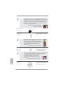
Installing a DIMM
Please make sure to disconnect power supply before adding or
removing DIMMs or the system components.
Step 1. Unlock a DIMM slot by pressing the retaining clips outward.
Step 2. Align a DIMM on the slot such that the notch on the DIMM matches the
break on the slot.
The DIMM only fi ts in one correct orientation. It will cause permanent
damage to the motherboard and the DIMM if you force the DIMM into the slot
at incorrect orientation.
Step 3. Firmly insert the DIMM into the slot until the retaining clips at both ends
fully snap back in place and the DIMM is properly seated.

16
ASRock H61iCafe Motherboard
English
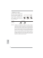
2.4 Expansion Slots (PCI and PCI Express Slots)
There are 2 PCI slot and 3 PCI Express slots on this motherboard.
PCI slots: PCI slots are used to install expansion cards that have the 32-bit PCI
interface.
PCIE slots:
PCIE1 (PCIE x16 slot; Blue) is used for PCI Express x16 lane width
graphics cards.
PCIE2 / PCIE3 (PCIE x1 slot; White) is used for PCI Express cards with
x1 lane width cards, such as Gigabit LAN card, SATA2 card, etc.
Installing an expansion card
Step 1. Before installing the expansion card, please make sure that the power
supply is switched off or the power cord is unplugged. Please read the
documentation of the expansion card and make necessary hardware
settings for the card before you start the installation.
Step 2. Remove the system unit cover (if your motherboard is already installed
in a chassis).
Step 3. Remove the bracket facing the slot that you intend to use. Keep the
screws for later use.
Step 4. Align the card connector with the slot and press fi rmly until the card is
completely seated on the slot.
Step 5. Fasten the card to the chassis with screws.
Step 6. Replace the system cover.

17
ASRock H61iCafe Motherboard
English
2. If you have installed onboard VGA driver from our support CD to your system
already, you can freely enjoy the benefi ts of dual monitor function after your
system boots. If you haven’t installed onboard VGA driver yet, please install
onboard VGA driver from our support CD to your system and restart your
computer.
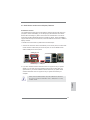
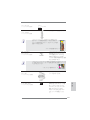
2.5 Dual Monitor and Surround Display Features
Dual Monitor Feature
This motherboard supports dual monitor feature. With the internal VGA output sup-
port (DVI-D, D-Sub and HDMI), you can easily enjoy the benefi ts of dual monitor
feature without installing any add-on VGA card to this motherboard. This mother-
board also provides independent display controllers for DVI-D, D-Sub and HDMI to
support dual VGA output so that DVI-D, D-sub and HDMI can drive same or different
display contents.
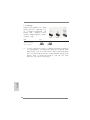
To enable dual monitor feature, please follow the below steps:
1. Connect DVI-D monitor cable to VGA/DVI-D port on the I/O panel, connect D-Sub
monitor cable to VGA/D-Sub port on the I/O panel, or connect HDMI monitor
cable to HDMI port on the I/O panel.
D-Sub, DVI-D and HDMI monitors cannot be enabled at the same time.
You can only choose the combination: DVI-D + HDMI, DVI-D + D-Sub,
or HDMI + D-Sub.
HDMI port
VGA/D-Sub port
VGA/DVI-D port

18
ASRock H61iCafe Motherboard
English
Surround Display Feature
This motherboard supports surround display upgrade. With the internal VGA output
support (DVI-D, D-Sub and HDMI) and external add-on PCI Express VGA cards,
you can easily enjoy the benefi ts of surround display feature.
Please refer to the following steps to set up a surround display environment:
1. Install the PCI Express VGA card on PCIE1 slot. Please refer to page 16 for
proper expansion card installation procedures for details.
2. Connect DVI-D monitor cable to VGA/DVI-D port on the I/O panel, connect D-Sub
monitor cable to VGA/D-Sub port on the I/O panel, or connect HDMI monitor
cable to HDMI port on the I/O panel. Then connect other monitor cables to the
corresponding connectors of the add-on PCI Express VGA card on PCIE1 slot.
3. Boot your system. Press <F2> or <Del> to enter UEFI setup. Enter “Onboard
VGA Share Memory” option to adjust the memory capability to [32MB], [64MB],
[128MB], [256MB] or [512MB] to enable the function of VGA/D-sub. Please make
sure that the value you select is less than the total capability of the system
memory. If you do not adjust the UEFI setup, the default value of “Onboard VGA
Share Memory”, [Auto], will disable VGA/D-Sub function when the add-on VGA
card is inserted to this motherboard.
4. Install the onboard VGA driver and the add-on PCI Express VGA card driver to
your system. If you have installed the drivers already, there is no need to install
them again.
5. Set up a multi-monitor display.
For Windows
®
XP / XP 64-bit OS:
Right click the desktop, choose “Properties”, and select the “Settings” tab
so that you can adjust the parameters of the multi-monitor according to
the steps below.
A. Click the “Identify” button to display a large number on each monitor.
B. Right-click the display icon in the Display Properties dialog that you
wish to be your primary monitor, and then select “Primary”. When
you use multiple monitors with your card, one monitor will always be
Primary, and all additional monitors will be designated as Secondary.
C. Select the display icon identifi ed by the number 2.
D. Click “Extend my Windows desktop onto this monitor”.
E. Right-click the display icon and select “Attached”, if necessary.
F. Set the “Screen Resolution” and “Color Quality” as appropriate for the
second monitor. Click “Apply” or “OK” to apply these new values.
G. Repeat steps C through E for the diaplay icon identifi ed by the number
one, two, three and four.

19
ASRock H61iCafe Motherboard
English
For Windows
®
7 / 7 64-bit / Vista
TM
/ Vista
TM
64-bit OS:
Right click the desktop, choose “Personalize”, and select the “Display
Settings” tab so that you can adjust the parameters of the multi-monitor
according to the steps below.
A. Click the number ”2” icon.
B. Click the items “This is my main monitor” and “Extend the desktop onto
this monitor”.
C. Click “OK” to save your change.
D. Repeat steps A through C for the display icon identifi ed by the number
three and four.
6. Use Surround Display. Click and drag the display icons to positions representing
the physical setup of your monitors that you would like to use. The placement
of display icons determines how you move items from one monitor to another.
HDCP Function
HDCP function is supported on this motherboard. To use HDCP
function with this motherboard, you need to adopt the monitor
that supports HDCP function as well. Therefore, you can enjoy
the superior display quality with high-defi nition HDCP
encryption contents. Please refer to below instruction for more
details about HDCP function.
What is HDCP?
HDCP stands for High-Bandwidth Digital Content Protection,
a specifi cation developed by Intel
®
for protecting digital
entertainment content that uses the DVI interface. HDCP is a
copy protection scheme to eliminate the possibility of
intercepting digital data midstream between the video source,
or transmitter - such as a computer, DVD player or set-top box -
and the digital display, or receiver - such as a monitor, television
or projector. In other words, HDCP specifi cation is designed to
protect the integrity of content as it is being transmitted.
Products compatible with the HDCP scheme such as DVD
players, satellite and cable HDTV set-top-boxes, as well as few
entertainment PCs requires a secure connection to a compliant
display. Due to the increase in manufacturers employing HDCP
in their equipment, it is highly recommended that the HDTV or
LCD monitor you purchase is compatible.

20
ASRock H61iCafe Motherboard
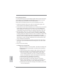
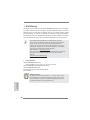
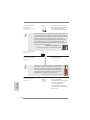
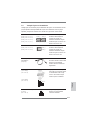
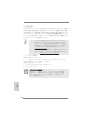
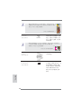
2.6 Jumpers Setup
The illustration shows how jumpers are
setup. When the jumper cap is placed on
pins, the jumper is “Short”. If no jumper cap
is placed on pins, the jumper is “Open”. The
illustration shows a 3-pin jumper whose
pin1 and pin2 are “Short” when jumper cap
is placed on these 2 pins.
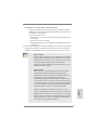
Jumper Setting Description
Clear CMOS Jumper
(CLRCMOS1)
(see p.2, No. 10)
Note: CLRCMOS1 allows you to clear the data in CMOS. To clear and reset the
system parameters to default setup, please turn off the computer and unplug
the power cord from the power supply. After waiting for 15 seconds, use a
jumper cap to short pin2 and pin3 on CLRCMOS1 for 5 seconds. However,
please do not clear the CMOS right after you update the BIOS. If you need
to clear the CMOS when you just fi nish updating the BIOS, you must boot
up the system fi rst, and then shut it down before you do the clear-CMOS ac-
tion. Please be noted that the password, date, time, user default profi le, 1394
GUID and MAC address will be cleared only if the CMOS battery is removed.
Clear CMOSDefault
English
Sayfa yükleniyor ...
Sayfa yükleniyor ...
Sayfa yükleniyor ...
Sayfa yükleniyor ...
Sayfa yükleniyor ...
Sayfa yükleniyor ...
Sayfa yükleniyor ...
Sayfa yükleniyor ...
Sayfa yükleniyor ...
Sayfa yükleniyor ...
Sayfa yükleniyor ...
Sayfa yükleniyor ...
Sayfa yükleniyor ...
Sayfa yükleniyor ...
Sayfa yükleniyor ...
Sayfa yükleniyor ...
Sayfa yükleniyor ...
Sayfa yükleniyor ...
Sayfa yükleniyor ...
Sayfa yükleniyor ...
Sayfa yükleniyor ...
Sayfa yükleniyor ...
Sayfa yükleniyor ...
Sayfa yükleniyor ...
Sayfa yükleniyor ...
Sayfa yükleniyor ...
Sayfa yükleniyor ...
Sayfa yükleniyor ...
Sayfa yükleniyor ...
Sayfa yükleniyor ...
Sayfa yükleniyor ...
Sayfa yükleniyor ...
Sayfa yükleniyor ...
Sayfa yükleniyor ...
Sayfa yükleniyor ...
Sayfa yükleniyor ...
Sayfa yükleniyor ...
Sayfa yükleniyor ...
Sayfa yükleniyor ...
Sayfa yükleniyor ...
Sayfa yükleniyor ...
Sayfa yükleniyor ...
Sayfa yükleniyor ...
Sayfa yükleniyor ...
Sayfa yükleniyor ...
Sayfa yükleniyor ...
Sayfa yükleniyor ...
Sayfa yükleniyor ...
Sayfa yükleniyor ...
Sayfa yükleniyor ...
Sayfa yükleniyor ...
Sayfa yükleniyor ...
Sayfa yükleniyor ...
Sayfa yükleniyor ...
Sayfa yükleniyor ...
Sayfa yükleniyor ...
Sayfa yükleniyor ...
Sayfa yükleniyor ...
Sayfa yükleniyor ...
Sayfa yükleniyor ...
Sayfa yükleniyor ...
Sayfa yükleniyor ...
Sayfa yükleniyor ...
Sayfa yükleniyor ...
Sayfa yükleniyor ...
Sayfa yükleniyor ...
Sayfa yükleniyor ...
Sayfa yükleniyor ...
Sayfa yükleniyor ...
Sayfa yükleniyor ...
Sayfa yükleniyor ...
Sayfa yükleniyor ...
Sayfa yükleniyor ...
Sayfa yükleniyor ...
Sayfa yükleniyor ...
Sayfa yükleniyor ...
Sayfa yükleniyor ...
Sayfa yükleniyor ...
Sayfa yükleniyor ...
Sayfa yükleniyor ...
Sayfa yükleniyor ...
Sayfa yükleniyor ...
Sayfa yükleniyor ...
Sayfa yükleniyor ...
Sayfa yükleniyor ...
Sayfa yükleniyor ...
Sayfa yükleniyor ...
Sayfa yükleniyor ...
Sayfa yükleniyor ...
Sayfa yükleniyor ...
Sayfa yükleniyor ...
Sayfa yükleniyor ...
Sayfa yükleniyor ...
Sayfa yükleniyor ...
Sayfa yükleniyor ...
Sayfa yükleniyor ...
Sayfa yükleniyor ...
Sayfa yükleniyor ...
Sayfa yükleniyor ...
Sayfa yükleniyor ...
Sayfa yükleniyor ...
Sayfa yükleniyor ...
Sayfa yükleniyor ...
Sayfa yükleniyor ...
Sayfa yükleniyor ...
Sayfa yükleniyor ...
Sayfa yükleniyor ...
Sayfa yükleniyor ...
Sayfa yükleniyor ...
Sayfa yükleniyor ...
Sayfa yükleniyor ...
Sayfa yükleniyor ...
Sayfa yükleniyor ...
Sayfa yükleniyor ...
Sayfa yükleniyor ...
Sayfa yükleniyor ...
Sayfa yükleniyor ...
Sayfa yükleniyor ...
Sayfa yükleniyor ...
Sayfa yükleniyor ...
Sayfa yükleniyor ...
Sayfa yükleniyor ...
Sayfa yükleniyor ...
Sayfa yükleniyor ...
Sayfa yükleniyor ...
Sayfa yükleniyor ...
Sayfa yükleniyor ...
Sayfa yükleniyor ...
Sayfa yükleniyor ...
Sayfa yükleniyor ...
Sayfa yükleniyor ...
Sayfa yükleniyor ...
Sayfa yükleniyor ...
Sayfa yükleniyor ...
Sayfa yükleniyor ...
Sayfa yükleniyor ...
Sayfa yükleniyor ...
Sayfa yükleniyor ...
-
 1
1
-
 2
2
-
 3
3
-
 4
4
-
 5
5
-
 6
6
-
 7
7
-
 8
8
-
 9
9
-
 10
10
-
 11
11
-
 12
12
-
 13
13
-
 14
14
-
 15
15
-
 16
16
-
 17
17
-
 18
18
-
 19
19
-
 20
20
-
 21
21
-
 22
22
-
 23
23
-
 24
24
-
 25
25
-
 26
26
-
 27
27
-
 28
28
-
 29
29
-
 30
30
-
 31
31
-
 32
32
-
 33
33
-
 34
34
-
 35
35
-
 36
36
-
 37
37
-
 38
38
-
 39
39
-
 40
40
-
 41
41
-
 42
42
-
 43
43
-
 44
44
-
 45
45
-
 46
46
-
 47
47
-
 48
48
-
 49
49
-
 50
50
-
 51
51
-
 52
52
-
 53
53
-
 54
54
-
 55
55
-
 56
56
-
 57
57
-
 58
58
-
 59
59
-
 60
60
-
 61
61
-
 62
62
-
 63
63
-
 64
64
-
 65
65
-
 66
66
-
 67
67
-
 68
68
-
 69
69
-
 70
70
-
 71
71
-
 72
72
-
 73
73
-
 74
74
-
 75
75
-
 76
76
-
 77
77
-
 78
78
-
 79
79
-
 80
80
-
 81
81
-
 82
82
-
 83
83
-
 84
84
-
 85
85
-
 86
86
-
 87
87
-
 88
88
-
 89
89
-
 90
90
-
 91
91
-
 92
92
-
 93
93
-
 94
94
-
 95
95
-
 96
96
-
 97
97
-
 98
98
-
 99
99
-
 100
100
-
 101
101
-
 102
102
-
 103
103
-
 104
104
-
 105
105
-
 106
106
-
 107
107
-
 108
108
-
 109
109
-
 110
110
-
 111
111
-
 112
112
-
 113
113
-
 114
114
-
 115
115
-
 116
116
-
 117
117
-
 118
118
-
 119
119
-
 120
120
-
 121
121
-
 122
122
-
 123
123
-
 124
124
-
 125
125
-
 126
126
-
 127
127
-
 128
128
-
 129
129
-
 130
130
-
 131
131
-
 132
132
-
 133
133
-
 134
134
-
 135
135
-
 136
136
-
 137
137
-
 138
138
-
 139
139
-
 140
140
-
 141
141
-
 142
142
-
 143
143
-
 144
144
-
 145
145
-
 146
146
-
 147
147
-
 148
148
-
 149
149
-
 150
150
-
 151
151
-
 152
152
-
 153
153
-
 154
154
-
 155
155
-
 156
156
-
 157
157
-
 158
158


Diğer dillerde
- español: ASROCK H61ICAFE El manual del propietario
- français: ASROCK H61ICAFE Le manuel du propriétaire
- italiano: ASROCK H61ICAFE Manuale del proprietario
- 日本語: ASROCK H61ICAFE 取扱説明書
- Deutsch: ASROCK H61ICAFE Bedienungsanleitung
- English: ASROCK H61ICAFE Owner's manual
- русский: ASROCK H61ICAFE Инструкция по применению
İlgili Makaleler
-
ASROCK H61M-U3S3 El kitabı
-
ASROCK P67 PRO Hızlı başlangıç Kılavuzu
-
ASROCK P67 Pro3 Hızlı başlangıç Kılavuzu
-
-
-
-
ASROCK B75 Pro3 Hızlı başlangıç Kılavuzu
-
ASROCK H77 Pro4/MVP Hızlı başlangıç Kılavuzu
-
-
