
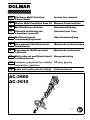
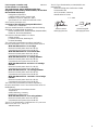
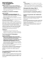
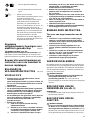
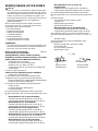
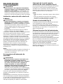
GB Cordless Multi Function Instruction manual
Power Head
F
Moteur Multi-Fonctions Sans Fil
Manuel d’instructions
D Multifunktions-Antrieb Betriebsanleitung
I Utensile multifunzione Istruzioni per l’uso
a benzina senza fili
NL Multifunctioneel Gebruiksaanwijzing
accuaandrijfsysteem
E Herramienta Multifuncional Manual de instrucciones
Inalámbrica
P Ferramenta Multifuncional Manual de instruções
a Bateria
DK Batteridrevet multifunktionelt Brugsanvisning
værktøjshoved
GR Ασύρματη μηχανοκίνητη κεφαλή Οδηγίες χρήσης
πολλαπλών χρήσεων
TR
Akülü Çok Fonksiyonlu Güç Başlığı Kullanım kılavuzu
AC-3600
AC-3610
012659

2
1 012661
2 012942 3 010814
4 010825 5 010815
1
2
3
4
5
6
7
8
9
10
11
1
12
3
13
A
B
14
15
16
1
2

3
6 012967 7 011715
8 013202 9 012660
10 012761 11 012762
2
17
18
6
19
5
20
21
22
23
21
24
1
2
3
4

4
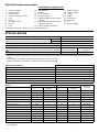
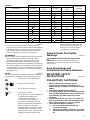
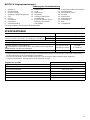
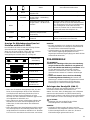
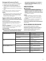
ENGLISH (Original instructions)
Explanation of general view
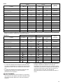
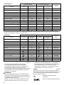
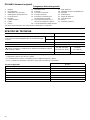
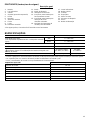
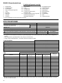
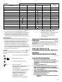
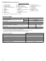
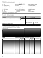
SPECIFICATIONS
• Due to our continuing program of research and development, the specifications herein are subject to change without
notice.
• Specifications and battery cartridge may differ from country to country.
• Weight, with battery cartridge, according to EPTA-Procedure 01/2003
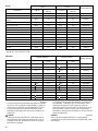
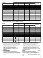
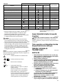
* Even if the sound pressure level listed above is 80 dB (A) or less, the level under working may exceed 80 dB (A). Wear
ear protection.
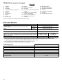
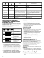
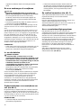
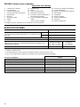
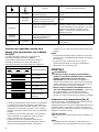
1. Battery cartridge
2. Indicator lamp
3. Switch trigger
4. Hanger (suspension point)
5. Grip
6. Barrier *
7. Shoulder harness
8. Buckle
9. Joint
10. Red indicator
11. Button
12. Lock-off button
13. Reversing switch
14. A position depressed for normal
operation
15. B position depressed for weed
and debris removal
16. Speed change switch lever
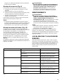
17. Indicator lamps
18. CHECK button
19. Clamp
20. Spacer
21. Arrow mark
22. Lock lever
23. Pin
24. Release button
* In some countries, the barrier is not provided with the tool.
Model AC-3600, AC-3610
No load speed
(with brushcutter attachment BC-AC and nylon cutting head)
High 0 - 6,600 min
-1
Low 0 - 4,900 min
-1
Overall length 1,019 mm
Rated voltage D.C. 36 V
Standard battery cartridge (and charger)
Always keep the combinations of battery/charger on the right columns.
AP-363 (LG-363)/
AP-3622 (LG-3622)
AD-3612
(LG-3600 K)
Net weight 4.6 kg 9.5 kg
Approved attachment Model
Edger attachment PE-CS
Brushcutter attachment BC-AC
Hedge trimmer attachment HT-CS, HT-CS 1
Pole saw attachment PS-CS, PS-CS 1
Coffee harvester attachment CH-CS
Cultivator attachment MC-CS
Shaft extension attachment SE-CS
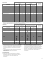
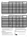
Noise Sound pressure level average Sound power level average
Applicable
standard
Attachment L
PA
(dB (A))
Uncertainty K
(dB (A))
L
WA
(dB (A))
Uncertainty K
(dB (A))
PE-CS 76.7 2.7 90.9 2.4 ISO11789
BC-AC (as a brushcutter) 80.1 2.5 93.5 2.5 EN11806
BC-AC (as a string trimmer) 78.6 2.5 91.7 2.5 EN786
HT-CS 86.0 2.5 94.8 2.5 ISO10517
HT-CS + SE-CS 81.8 3.0 97.3 3.0 ISO10517
HT-CS 1 83.5 2.3 92.8 2.6 ISO10517
HT-CS 1 + SE-CS 79.8 1.8 93.4 2.1 ISO10517
PS-CS 91.9 2.5 100.9 2.5 ISO11680
PS-CS + SE-CS 88.8 2.5 102.9 2.5 ISO11680
PS-CS 1 93.6 2.5 101.9 2.5 ISO11680
PS-CS 1 + SE-CS 90.3 2.5 104.4 2.5 ISO11680
CH-CS 78.2 2.5 87.1 2.5 ISO10517
CH-CS + SE-CS 81.9 2.5 95.2 2.5 ISO10517
MC-CS 78.8 2.5 88.3 2.5 EN709

5
ENG901-1
• The declared vibration emission value has been
measured in accordance with the standard test method
and may be used for comparing one tool with another.
• The declared vibration emission value may also be
used in a preliminary assessment of exposure.
WARNING:
• The vibration emission during actual use of the power
tool can differ from the declared emission value
depending on the ways in which the tool is used.
• Be sure to identify safety measures to protect the
operator that are based on an estimation of exposure in
the actual conditions of use (taking account of all parts
of the operating cycle such as the times when the tool
is switched off and when it is running idle in addition to
the trigger time).
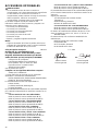
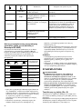
Symbol
END018-3
The following show the symbols used for the equipment.
Be sure that you understand their meaning before use.
....................... Take particular care and attention.
..........Read instruction manual.
...................... Do not expose to moisture.
............... Only for EU countries
Do not dispose of electric equipment
or battery pack together with
household waste material!
In observance of the European
Directives, on Waste Electric and
Electronic Equipment and Batteries
and Accumulators and Waste
Batteries and Accumulators and their
implementation in accordance with
national laws, electric equipment and
batteries and battery pack(s) that
have reached the end of their life
must be collected separately and
returned to an environmentally
compatible recycling facility.
General Power Tool Safety
Warnings
GEA010-1
WARNING Read all safety warnings and all
instructions. Failure to follow the warnings and
instructions may result in electric shock, fire and/or
serious injury.
Save all warnings and
instructions for future reference.
IMPORTANT SAFETY
INSTRUCTIONS
ENC007-8
FOR BATTERY CARTRIDGE
1. Before using battery cartridge, read all
instructions and cautionary markings on (1)
battery charger, (2) battery, and (3) product using
battery.
2. Do not disassemble battery cartridge.
3. If operating time has become excessively shorter,
stop operating immediately. It may result in a risk
of overheating, possible burns and even an
explosion.
4. If electrolyte gets into your eyes, rinse them out
with clear water and seek medical attention right
away. It may result in loss of your eyesight.
5. Do not short the battery cartridge:
(1) Do not touch the terminals with any
conductive material.
(2) Avoid storing battery cartridge in a container
with other metal objects such as nails, coins,
etc.
Vibration Left handle (Front grip) Right handle (Rear grip)
Applicable
standard
Attachment a
h
(m/s
2
)
Uncertainty K
(m/s
2
)
a
h
(m/s
2
)
Uncertainty K
(m/s
2
)
PE-CS 1.9 1.5 1.2 1.5 ISO11789
BC-AC (as a brushcutter) 2.5 1.5 2.5 1.5 EN11806
BC-AC (as a string trimmer) 4.0 1.5 2.5 1.5 EN786
HT-CS 3.5 1.5 2.5 1.5 ISO10517
HT-CS + SE-CS 3.0 2.0 2.5 2.0 ISO10517
HT-CS 1 5.5 1.5 2.5 1.5 ISO10517
HT-CS 1 + SE-CS 3.5 1.5 2.5 1.5 ISO10517
PS-CS 2.5 1.5 2.5 1.5 ISO11680
PS-CS + SE-CS 2.5 2.0 2.5 2.0 ISO11680
PS-CS 1 2.5 2.0 2.5 2.0 ISO11680
PS-CS 1 + SE-CS 2.5 2.0 2.5 2.0 ISO11680
CH-CS 3.5 1.5 3.0 1.5 ISO10517
CH-CS + SE-CS 2.5 2.0 2.6 2.0 ISO10517
MC-CS 2.5 1.5 2.5 1.5 EN709
Cd
Ni-MH
Li-ion

6
(3) Do not expose battery cartridge to water or
rain.
A battery short can cause a large current flow,
overheating, possible burns and even a
breakdown.
6. Do not store the tool and battery cartridge in
locations where the temperature may reach or
exceed 50°C (122°F).
7. Do not incinerate the battery cartridge even if it is
severely damaged or is completely worn out. The
battery cartridge can explode in a fire.
8. Be careful not to drop or strike battery.
9. Do not use a damaged battery.
10. Follow your local regulations relating to disposal
of battery.
SAVE THESE INSTRUCTIONS.
Tips for maintaining maximum battery life
1. Charge the battery cartridge before completely
discharged.
Always stop tool operation and charge the battery
cartridge when you notice less tool power.
2. Never recharge a fully charged battery cartridge.
Overcharging shortens the battery service life.
3. Charge the battery cartridge with room
temperature at 10°C - 40°C (50°F - 104°F). Let a hot
battery cartridge cool down before charging it.
4. Charge the battery cartridge once in every six
months if you do not use it for a long period of
time.
INTENDED USE
This cordless multi function power head is intended for
driving an approved attachment listed in the section
“SPECIFICATIONS” of this instruction manual. Never use
the unit for the other purpose.
WARNING:
• Read the instruction manual of the attachment as
well as this instruction manual before using. Failure
to follow the warnings and instructions may result
serious injury.
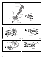
PARTS DESCRIPTION (Fig. 1)
NOTE:
* In some countries, the barrier is not provided with the
tool.
FUNCTIONAL DESCRIPTION
WARNING:
• Always be sure that the tool is switched off and the
battery cartridge is removed before adjusting or
checking functions on the tool. Failure to switch off
and remove the battery cartridge may result in serious
personal injury from accidental start-up.
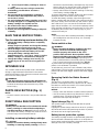
Installing or removing battery cartridge
CAUTION:
• Hold the tool and the battery cartridge firmly when
installing or removing battery cartridge. Failure to
hold the tool and the battery cartridge firmly may cause
them to slip off your hands and result in damage to the
tool and battery cartridge and a personal injury.
• Always switch off the tool before installing or removing
of the battery cartridge. (Fig. 2)
To remove the battery cartridge, slide it from the tool while
sliding the button on the front of the cartridge.
To install the battery cartridge, align the tongue on the
battery cartridge with the groove in the housing and slip it
into place. Always insert it all the way until it locks in place
with a little click. If you can see the red indicator on the
upper side of the button, it is not locked completely. Install
it fully until the red indicator cannot be seen. If not, it may
accidentally fall out of the tool, causing injury to you or
someone around you.
NOTE:
• Do not use force when installing the battery cartridge. If
the cartridge does not slide in easily, it is not being
inserted correctly.
Power switch action
WARNING:
• Before inserting the battery cartridge in the tool,
always check to see that the switch trigger
actuates properly and returns to the “OFF”
position when released. Do not pull the switch
trigger hard without pressing in the lock-off button.
This can cause switch breakage. Operating a tool
with a switch that does not actuate properly can lead to
loss of control and serious personal injury. (Fig. 3)
To prevent the switch trigger from being accidentally
pulled, a lock-off button is provided.
To start the tool, press in the lock-off button and pull the
switch trigger. The tool speed is increased by increasing
pressure on the switch trigger. Release the switch trigger
to stop.
Reversing Switch for Debris Removal
(Fig. 4)
This tool has a reversing switch. To remove debris
jammed or entangled in the tool, depress the “B” side of
the switch to reverse the rotation. For normal operation,
depress the “A” side of the switch.
NOTICE:
• Always check the direction of rotation before operation.
• Use the reversing switch only after the tool comes to a
complete stop. Changing the direction of rotation
before the tool stops may damage it.
Speed change (Fig. 5)
Two speed ranges can be preselected with the speed
change switch.
Flipping the speed change switch lever to the “1” position
will set the tool to the low speed range and the “2” position
will set the tool to the high speed range.
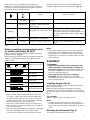
Battery/motor protection system
The battery cartridge and tool are provided with protection
devices that will automatically reduce or cut off power to
the tool when overload situations develop that may cause
damage to the tool or battery cartridge.

7
If the tool becomes overloaded but not locked up a
protector is provided to reduce the revolutions to protect
the motor. In this case the two indicator lamps described
in the table below do not light or blink.
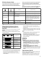
All other protection functions can be identified by the
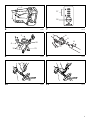
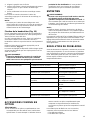
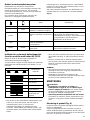
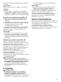
indicator lamps described in the table below. (Fig. 6)
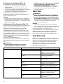
010823
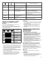
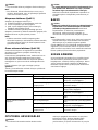
Battery remaining capacity indicator (only
for models with Battery AP-3622)
Battery AP-3622 is equipped with the battery remaining
capacity indicator. (Fig. 7)
Press the CHECK button to indicate the battery remaining
capacity. The indicator lamps will then light for approx.
three seconds.
011713
• When only the lowermost indicator lamp (next to the
“E”) blinks, or when none of the indicator lamps light,
the battery capacity has run out, so the tool does not
operate. In these cases, charge the battery or replace
the empty battery with a fully charged one.
• When two or more indicator lamps do not light even
after charging is complete, the battery has reached the
end of its service life.
• When the upper two and lower two indicator lamps light
alternately, the battery may have malfunctioned.
Contact your local Dolmar authorized service center.
NOTE:
• The indicated capacity may be lower than the actual
level during use or immediately after using the tool.
• Depending on the conditions of use and the ambient
temperature, the indication may differ slightly from the
actual capacity.
ASSEMBLY
WARNING:
• Always be sure that the tool is switched off and
battery cartridge is removed before carrying out
any work on the tool. Failure to switch off and remove
the battery cartridge may result in serious personal
injury from accidental start-up.
• Never start the tool unless it is completely
assembled. Operation of the tool in a partially
assembled state may result in serious personal injury
from accidental start-up.
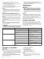
Installing the grip (Fig. 8)
Securely fit the barrier and grip onto the shaft pipe with
two screws and clamps.
Make sure that the grip/barrier assembly is located
between the spacer and the arrow mark. Do not remove
or shrink the spacer. Once assembled, do not remove the
barrier.
CAUTION:
• Never install the grip on the label or joint.
NOTE:
• In some countries, the barrier and spacer are not
provided with the tool. In that case, align the handle to
further side of the line which is indicated by the arrow
marks.
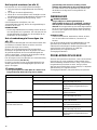
Mounting the attachment (Fig. 9)
To mount the attachment to a power unit:
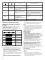
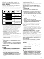
Status Action to be taken
– Blinking
Battery power has been nearly
used up.
Replace the battery with fully charged one.
– Lighting On
Battery protector is shutting off
the power - battery power has
been used up.
Replace the battery with fully charged one.
Blinking –
Overload protector is shutting off
the power - the motor was locked.
Release the switch trigger and remove the
cause of the motor lock or overload. If the
cutting tool is locked by entangling weeds or the
like, always remove the battery cartridge before
clearing it.
Lighting On –
Overheat protector is shutting
off the power - overheating.
Rest the equipment for a while.
Blinking Blinking
Electric or electronic malfunction Ask your local authorized service center for
repairs.
Indicator lamps
Remaining capacity
Lighted Off Blinking
E F
70% to 100%
45% to 70%
20% to 45%
0% to 20%
Charge the battery.
The battery may
have malfunctioned.

8
1. Make sure that the lock lever is not tightened.
2. Align the pin with the arrow mark.
3. Insert the shaft into the drive shaft of the power unit
until the release button pops up.
4. Tighten the lock lever firmly as shown.
To remove the attachment, loosen the lock lever, press
the lock button and withdraw the shaft.
NOTICE:
• Do not tighten the lock lever without the shaft of the
attachment inserted. Otherwise the lock lever may
tighten the entrance of the drive shaft too much and
damage it.
Attaching shoulder harness (Fig. 10)
Put the shoulder harness on your left shoulder by putting
your head and right arm through it. Keep the tool on your
right side.
After putting the shoulder harness, attach it to the tool by
connecting the buckles provided on both the tool hook
and the harness. Be sure that the buckles click and lock
completely in place.
Adjust the strap to the suitable length for your operation.
(Fig. 11)
The buckle is provided with a means of quick release
which can be accomplished by simply squeezing the
sides and the buckle.
WARNING:
• Be extremely careful to maintain control of the tool
at all times. Do not allow the tool to be deflected
toward you or anyone in the work vicinity. Failure to
keep control of the tool could result in serious injury to
the bystander and the operator.
MAINTENANCE
WARNING:
• Always be sure that the tool is switched off and
battery cartridge is removed before attempting to
perform inspection or maintenance on the tool.
Failure to switch off and remove the battery cartridge
may result in serious personal injury from accidental
start-up.
NOTICE:
• Never use gasoline, benzine, thinner, alcohol or the
like. Discoloration, deformation or cracks may result.
To maintain product SAFETY and RELIABILITY, repairs,
any other maintenance or adjustment should be
performed by Dolmar Authorized Service Centers, always
using Dolmar replacement parts.
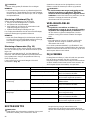
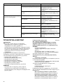
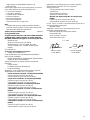
TROUBLE SHOOTING
Before asking for repairs, conduct your own inspection
first. If you find a problem that is not explained in the
manual, do not attempt to dismantle the tool. Instead, ask
Dolmar Authorized Service Centers, always using Dolmar
replacement parts for repairs.
012662
OPTIONAL ACCESSORIES
CAUTION:
• These accessories or attachments are recommended
for use with your Dolmar tool specified in this manual.
The use of any other accessories or attachments might
present a risk of injury to persons. Only use accessory
or attachment for its stated purpose.
If you need any assistance for more details regarding
these accessories, ask your local Dolmar Service Center.
• Brushcutter attachment
• Hedge trimmer attachment
• Pole saw attachment
• Cultivator attachment
• Coffee harvester attachment
• Shaft extension attachment
• Dolmar genuine battery and charger
NOTE:
• Some items in the list may be included in the tool
package as standard accessories. They may differ
from country to country.
Malfunction status Cause Action
Motor does not run. Battery cartridge is not installed. Install the battery cartridge.
Battery problem (under voltage) Recharge the battery. If recharging is
not effective, replace battery.
The drive system does not work
correctly.
Ask your local authorized service center
for repair.
Motor stops running after a little use. Rotation is in reverse. Change the direction of rotation with the
reversing switch.
Battery’s charge level is low. Recharge the battery. If recharging is
not effective, replace battery.
Overheating. Stop using of tool to allow it to cool
down.
It does not reach maximum RPM. Battery is installed improperly. Install the battery cartridge as described
in this manual.
Battery power is dropping. Recharge the battery. If recharging is
not effective, replace battery.
The drive system does not work
correctly.
Ask your local authorized service center
for repair.

9
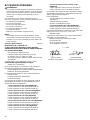
For European countries only
ENH043-2
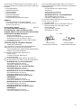
EC Declaration of Conformity
The undersigned, Tamiro Kishima and Rainer
Bergfeld, as authorized by Dolmar GmbH, declare that
the DOLMAR machine(s):
Designation of Machine:
Cordless Multi Function Power Head
Model No./ Type: AC-3600, AC-3610
Specifications: see “SPECIFICATIONS” table.
are of series production and
Conforms to the following European Directives:
2000/14/EC, 2006/42/EC
And are manufactured in accordance with the following
standards or standardised documents:
EN709, EN/ISO10517, EN/ISO11680, EN/ISO11806,
EN60745, ISO11789, EN60335
The technical documentation is on file at:
Dolmar GmbH,
Jenfelder Straße 38, Abteilung FZ,
D-22045 Hamburg
The conformity assessment procedure required by
Directive 2000/14/EC was in Accordance with annex V.
With attachment PE-CS as an edger
Measured sound power level 90.9 dB (A)
Guaranteed sound power level 94 dB (A)
With attachment BC-AC as a brushcutter
Measured sound power level 93.1 dB (A)
Guaranteed sound power level 95 dB (A)
With attachment HT-CS as a hedge trimmer
Measured sound power level 94.6 dB (A)
Guaranteed sound power level 97 dB (A)
With attachment HT-CS and SE-CS as a hedge
trimmer
Measured sound power level 97.0 dB (A)
Guaranteed sound power level 100 dB (A)
With attachment HT-CS 1 as a hedge trimmer
Measured sound power level 92.8 dB (A)
Guaranteed sound power level 95 dB (A)
With attachment HT-CS 1 and SE-CS as a hedge
trimmer
Measured sound power level 93.4 dB (A)
Guaranteed sound power level 95 dB (A)
The conformity assessment procedure required by
Directive 2000/14/EC was in Accordance with annex VI.
Notified Body:
TÜV Rheinland LGA Products GmbH
Tillystraße 2
90431 Nürnberg, Germany
Identification number 0197
With attachment BC-AC as a string trimmer
Measured sound power level 91.6 dB (A)
Guaranteed sound power level 94 dB (A)
The EC-Type Examination Certificate No. as a pole saw
with PS-CS, PS-CS 1, SE-CS is:
4811008.12005
The EC-Type Examination per 2006/42/EC was
performed by:
DEKRA Testing and Certification GmbH
Enderstraße 92b
01277 Dresden, Germany
Identification No. 2140
2. 7. 2013
Tamiro Kishima Rainer Bergfeld
Managing Director Managing Director

10
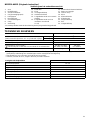
FRANÇAIS (Instructions d’origine)
Descriptif
SPÉCIFICATIONS
• Étant donné l’évolution constante de notre programme de recherche et de développement, les spécifications
contenues dans ce manuel sont sujettes à des modifications sans préavis.
• Les spécifications et la batterie peuvent varier d’un pays à l’autre.
• Poids, batterie incluse, selon la procédure EPTA 01/2003
1. Batterie
2. Voyant
3. Gâchette
4. Crochet (point de suspension)
5. Manche
6. Écran *
7. Bandoulière
8. Boucle
9. Joint
10. Partie rouge
11. Bouton
12. Bouton de sécurité
13. Inverseur
14. Position A pour le fonctionnement
normal
15. Position B pour le retrait des
herbes et des débris
16. Levier de l’interrupteur de
changement de vitesse
17. Voyants
18. Bouton CHECK
19. Dispositif de serrage
20. Douille d’écartement
21. Flèche
22. Levier de verrouillage
23. Goupille
24. Bouton de déblocage
* Dans certains pays, l’écran n’est pas fourni avec l’outil.
Modèle AC-3600, AC-3610
Vitesse à vide
(avec la tête débroussailleuse BC-AC et la tête à fil de
nylon)
Élevée Entre 0 et 6 600 min
-1
Faible Entre 0 et 4 900 min
-1
Longueur totale 1 019 mm
Tension nominale 36 V C.C.
Batterie standard (et chargeur)
Associez toujours les batteries et chargeurs comme indiqué dans les
colonnes de droite.
AP-363 (LG-363)/
AP-3622 (LG-3622)
AD-3612
(LG-3600 K)
Poids net 4,6 kg 9,5 kg
Fixation approuvée Modèle
Tête dresse-bordures PE-CS
Tête débroussailleuse BC-AC
Tête taille-haie à perche HT-CS, HT-CS 1
Tête élagueuse à perche PS-CS, PS-CS 1
Tête peigne vibreur pour café CH-CS
Tête moto-bineuse MC-CS
Rallonge d’arbre SE-CS

11
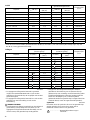
* Même si le niveau de pression sonore indiqué ci-dessus est de 80 dB (A) ou moins, le niveau en fonctionnement peut
dépasser 80 dB (A). Portez des protections auditives.
ENG901-1
• La valeur de l’émission des vibrations déclarée a été
mesurée conformément à la méthode de test standard
et peut être utilisée afin de comparer des outils entre
eux.
• La valeur de l’émission des vibrations déclarée peut
également être utilisée lors d’une évaluation
préliminaire de l’exposition.
AVERTISSEMENT:
• Selon la manière dont l’outil est utilisé, il est possible
que l’émission des vibrations pendant l’utilisation réelle
de l’outil électrique diffère de la valeur de l’émission
déclarée.
• Veillez à identifier les mesures de sécurité destinées à
protéger l’opérateur et établies en fonction de
l’estimation de l’exposition dans les conditions réelles
d’utilisation (en prenant en compte toutes les étapes du
cycle de fonctionnement, telles que les périodes de
mise hors tension de l’outil, les périodes de
fonctionnement au ralenti et les périodes de mise en
route).
Bruit Niveau moyen de pression
sonore
Niveau moyen de puissance
sonore
Norme
applicable
Fixation L
PA
(dB (A))
Incertitude K
(dB (A))
L
WA
(dB (A))
Incertitude K
(dB (A))
PE-CS 76,7 2,7 90,9 2,4 ISO11789
BC-AC (comme une
débroussailleuse)
80,1 2,5 93,5 2,5 EN11806
BC-AC (comme un coupe herbe) 78,6 2,5 91,7 2,5 EN786
HT-CS 86,0 2,5 94,8 2,5 ISO10517
HT-CS + SE-CS 81,8 3,0 97,3 3,0 ISO10517
HT-CS 1 83,5 2,3 92,8 2,6 ISO10517
HT-CS 1 + SE-CS 79,8 1,8 93,4 2,1 ISO10517
PS-CS 91,9 2,5 100,9 2,5 ISO11680
PS-CS + SE-CS 88,8 2,5 102,9 2,5 ISO11680
PS-CS 1 93,6 2,5 101,9 2,5 ISO11680
PS-CS 1 + SE-CS 90,3 2,5 104,4 2,5 ISO11680
CH-CS 78,2 2,5 87,1 2,5 ISO10517
CH-CS + SE-CS 81,9 2,5 95,2 2,5 ISO10517
MC-CS 78,8 2,5 88,3 2,5 EN709
Vibrations Poignée gauche (Manche avant) Poignée droite (Manche arrière)
Norme
applicable
Fixation a
h
(m/s
2
)
Incertitude K
(m/s
2
)
a
h
(m/s
2
)
Incertitude K
(m/s
2
)
PE-CS 1,9 1,5 1,2 1,5 ISO11789
BC-AC (comme une
débroussailleuse)
2,5 1,5 2,5 1,5 EN11806
BC-AC (comme un coupe herbe) 4,0 1,5 2,5 1,5 EN786
HT-CS 3,5 1,5 2,5 1,5 ISO10517
HT-CS + SE-CS 3,0 2,0 2,5 2,0 ISO10517
HT-CS 1 5,5 1,5 2,5 1,5 ISO10517
HT-CS 1 + SE-CS 3,5 1,5 2,5 1,5 ISO10517
PS-CS 2,5 1,5 2,5 1,5 ISO11680
PS-CS + SE-CS 2,5 2,0 2,5 2,0 ISO11680
PS-CS 1 2,5 2,0 2,5 2,0 ISO11680
PS-CS 1 + SE-CS 2,5 2,0 2,5 2,0 ISO11680
CH-CS 3,5 1,5 3,0 1,5 ISO10517
CH-CS + SE-CS 2,5 2,0 2,6 2,0 ISO10517
MC-CS 2,5 1,5 2,5 1,5 EN709

12
Symbole
END018-3
Les symboles utilisés pour l’appareil sont indiqués ci-
dessous. Assurez-vous d’avoir bien compris leur
signification avant d’utiliser l’appareil.
....................... Usez d’attention et de soins
particuliers.
..........Reportez-vous au manuel
d’instructions.
...................... Tenez l’appareil à l’abri de l’humidité.
...............Pour les pays européens uniquement
Ne pas jeter les appareils électriques
et les bloc-batteries dans les ordures
ménagères !
Conformément aux directives
européennes relatives aux déchets
d’équipements électriques ou
électroniques (DEEE) ainsi qu’aux
batteries, aux accumulateurs et aux
batteries et accumulateurs usagés et
à leur transposition dans la législation
nationale, les appareils électriques,
les batteries et les bloc-batteries
doivent être collectés à part et être
soumis à un recyclage respectueux
de l’environnement.
Consignes de sécurité générales
des outils électriques GEA010-1
AVERTISSEMENT Veuillez lire toutes les
consignes de sécurité et les instructions. Il y a un
risque de choc électrique, d’incendie et/ou de blessure
grave si les consignes et les instructions ne sont pas
toutes respectées.
Conservez toutes les consignes
et instructions pour référence
ultérieure.
CONSIGNES DE SÉCURITÉ
IMPORTANTES
ENC007-8
POUR LA BATTERIE
1. Avant d’utiliser la batterie, veuillez lire toutes les
instructions et tous les avertissements inscrits
sur (1) le chargeur, (2) la batterie et (3) l’appareil
alimenté par la batterie.
2. Ne démontez pas la batterie.
3. Cessez immédiatement d’utiliser l’outil si le temps
de fonctionnement devient excessivement court. Il
y a risque de surchauffe, de brûlures, voire
d’explosion.
4. Si l’électrolyte pénètre dans vos yeux, rincez-les à
l’eau claire et consultez immédiatement un
médecin. Il y a risque de perte de la vue.
5. Évitez de court-circuiter la batterie :
(1) Ne touchez les bornes avec aucun matériau
conducteur.
(2) Évitez de ranger la batterie dans un
contenant où se trouvent d’autres objets
métalliques tels que des clous, pièces de
monnaie, etc.
(3) N’exposez pas la batterie à l’eau ou à la pluie.
Un court-circuit de la batterie risque de provoquer
un fort courant, une surchauffe, parfois des
brûlures et même une panne.
6. Ne rangez pas l’outil ou la batterie dans des
endroits où la température risque d’atteindre ou
de dépasser 50°C (122°F).
7. Ne jetez pas la batterie au feu même si elle est
sérieusement endommagée ou complètement
épuisée. La batterie peut exploser au contact du
feu.
8. Veillez à ne pas laisser tomber ou heurter la
batterie.
9. N’utilisez pas de batterie endommagée.
10. Respectez les réglementations locales relatives à
la mise au rebut des batteries.
CONSERVEZ CES
INSTRUCTIONS.
Conseils pour assurer la durée de vie
optimale de la batterie
1. Rechargez la batterie avant qu’elle ne soit
complètement épuisée.
Arrêtez toujours l’outil et rechargez la batterie
quand vous constatez que la puissance de l’outil
diminue.
2. Ne rechargez jamais une batterie complètement
chargée.
La surcharge réduit la durée de service de la
batterie.
3. Chargez la batterie alors que la température de la
pièce se trouve entre 10°C et 40°C (50°F et 104°F).
Si une batterie est chaude, laissez-la refroidir
avant de la charger.
4. Si vous n’utilisez pas l’outil pendant une période
prolongée, rechargez la batterie tous les six mois.
USAGE PRÉVU
Le moteur multi-fonctions sans fil est destiné à faire
fonctionner un accessoire approuvé répertorié dans la
section « SPÉCIFICATIONS » de ce manuel
d’instructions. N’utilisez jamais l’appareil à d’autres fins.
AVERTISSEMENT :
• Lisez le manuel d’instructions de l’accessoire,
ainsi que ce manuel d’instructions avant d’utiliser
l’outil. Le non-respect des mises en garde et
instructions peut entraîner de graves blessures.
DESCRIPTION DES PIÈCES
(Fig. 1)
REMARQUE :
* Dans certains pays, l’écran n’est pas fourni avec l’outil.
Cd
Ni-MH
Li-ion

13
DESCRIPTION DU
FONCTIONNEMENT
AVERTISSEMENT :
• Veillez toujours à ce que l’outil soit éteint et la
batterie déposée avant d’effectuer des réglages ou
de vérifier le fonctionnement de l’outil. Si vous ne
mettez pas l’outil hors tension et ne retirez pas la
batterie, vous risquez de vous blesser grièvement en
cas de démarrage accidentel.
Installation ou retrait de la batterie
ATTENTION :
• Tenez fermement l’outil et la batterie lors de
l’installation ou du retrait de la batterie. Si vous ne
tenez pas fermement l’outil et la batterie, ils risquent de
glisser et de s’abîmer ou de vous blesser.
• Éteignez toujours l’outil avant d’installer ou de déposer
la batterie. (Fig. 2)
Pour retirer la batterie, faites glisser le bouton à l’avant de
la batterie et sortez la batterie.
Pour installer la batterie, alignez sa languette sur la
rainure qui se trouve à l’intérieur du carter, puis glissez la
batterie pour la mettre en place. Insérez-la toujours bien à
fond, jusqu’à ce qu’elle se verrouille en émettant un léger
clic. Si vous pouvez voir la partie rouge sur la face
supérieure du bouton, la batterie n’est pas parfaitement
verrouillée. Installez-la à fond, jusqu’à ce que la partie
rouge ne soit plus visible. Sinon, elle risque de tomber
accidentellement de l’outil, en vous blessant ou en
blessant une personne située près de vous.
REMARQUE :
• N’appliquez pas une force excessive lors de
l’installation de la batterie. Si la batterie ne glisse pas
aisément, c’est qu’elle n’est pas insérée correctement.
Fonctionnement de l’interrupteur
AVERTISSEMENT :
• Avant d’insérer la batterie dans l’outil, vérifiez
toujours que la gâchette fonctionne bien et revient
en position d’arrêt lorsqu’elle est relâchée.
N’appuyez pas fortement sur la gâchette sans avoir
d’abord enfoncé le bouton de sécurité. Vous
risqueriez de casser la gâchette. L’utilisation d’un
outil dont la gâchette ne fonctionne pas correctement
risque de provoquer une perte de contrôle et de graves
blessures corporelles. (Fig. 3)
Pour éviter tout déclenchement accidentel de la gâchette,
l’outil est muni d’un bouton de sécurité.
Pour faire démarrer l’outil, enfoncez le bouton de sécurité
puis appuyez sur la gâchette. La vitesse de l’appareil
augmente à mesure que vous augmentez la pression
exercée sur la gâchette. Pour l’arrêter, relâchez la
gâchette.
Inversement de l’interrupteur pour retirer
les débris (Fig. 4)
Cet outil est équipé d’un inverseur de polarité. Pour retirer
les débris coincés ou emmêlés dans l’outil, appuyez sur le
côté « B » de l’interrupteur pour inverser la rotation. Pour
un fonctionnement normal, appuyez sur le côté « A » de
l’interrupteur.
NOTE :
• Vérifiez toujours le sens de rotation avant de mettre
l’outil en marche.
• N’actionnez l’inverseur qu’une fois l’outil complètement
arrêté. Si vous changez le sens de rotation de l’outil
avant l’arrêt de celui-ci, vous risquez de l’endommager.
Changement de vitesse (Fig. 5)
Deux vitesses peuvent être sélectionnées avec
l’interrupteur de changement de vitesse.
Si vous mettez le levier de l’interrupteur de changement
de vitesse en position 1, l’outil fonctionnera à faible
vitesse et en position 2, il fonctionnera à vitesse élevée.
Système de protection de la batterie/du
moteur
La batterie et l’outil sont fournis avec des protections qui
réduisent ou coupent automatiquement l’alimentation de
l’outil en cas de surcharges susceptibles de les
endommager.
Si l’outil est surchargé mais pas verrouillé, une protection
réduit le régime afin de préserver le moteur. Dans ce cas,
les deux voyants décrits dans le tableau ci-dessous ne
s’allument ou ne clignotent pas.
Toutes les autres fonctions de protection peuvent être
identifiées par les voyants décrits dans le tableau ci-
dessous. (Fig. 6)

14
010823
Voyant d’autonomie de la batterie
(uniquement pour les modèles équipés
d’une batterie AP-3622)
La batterie AP-3622 est équipée du voyant d’autonomie
restante de la batterie. (Fig. 7)
Appuyez sur le bouton CHECK pour indiquer l’autonomie
restante de la batterie. Les voyants s’allument alors
pendant trois secondes environ.
011713
• Lorsque seul le voyant le plus bas (près de la lettre
« E ») clignote, ou lorsque aucun des voyants ne
s’allume, la batterie est vide donc l’outil ne fonctionne
pas. Dans ce cas, rechargez la batterie ou remplacez
la batterie vide par une batterie entièrement chargée.
• Si au moins deux voyants ne s’allument pas même une
fois le chargement terminé, cela signifie que la batterie
arrive en fin de vie.
• Lorsque les deux voyants supérieurs et inférieurs
s’allument à tour de rôle, cela signifie que la batterie a
peut-être mal fonctionné. Contactez votre centre de
service agréé Dolmar le plus proche.
REMARQUE :
• L’autonomie restante indiquée peut être inférieure au
niveau réel pendant ou immédiatement après
l’utilisation de l’outil.
• Selon les conditions d’utilisation et la température
ambiante, les indications peuvent différer légèrement
de l’autonomie réelle restante.
ASSEMBLAGE
AVERTISSEMENT :
• Assurez-vous toujours que l’outil est hors tension
et la batterie retirée avant d’effectuer toute
intervention sur l’outil. Si vous ne mettez pas l’outil
hors tension et ne retirez pas la batterie, vous risquez
de vous blesser grièvement en cas de démarrage
accidentel.
• Ne démarrez jamais l’outil avant qu’il soit
complètement assemblé. Si vous le faites fonctionner
alors qu’il n’est pas parfaitement assemblé, vous
risquez de vous blesser grièvement en cas de
démarrage accidentel.
Installation du manche (Fig. 8)
Placez solidement l’écran et le manche sur le tuyau de
l’arbre avec deux vis et dispositifs de serrage.
Assurez-vous que l’ensemble manche/écran se trouve
entre la douille d’écartement et la flèche. Ne retirez pas et
ne comprimez pas la douille d’écartement. Une fois
l’assemblage terminé, ne retirez pas l’écran.
ATTENTION :
• N’installez jamais le manche sur l’étiquette ou le joint.
REMARQUE :
• Dans certains pays, l’écran et la douille d’écartement
ne sont pas fournis avec l’outil. Dans ce cas, alignez le
manche sur le côté de la ligne indiqué par les flèches.
Montage de l’accessoire (Fig. 9)
Pour fixer l’accessoire au groupe moteur :
1. Assurez-vous que le levier de verrouillage n’est pas
serré.
État Mesure à prendre
– Clignotant
La batterie est presque
déchargée.
Remplacez la batterie par une batterie
rechargée.
– S’allume
Le dispositif de protection de la
batterie met l’appareil hors
tension : la batterie est
déchargée.
Remplacez la batterie par une batterie
rechargée.
Clignotant –
Le dispositif de protection contre
les surcharges met l’appareil hors
tension : le moteur est verrouillé.
Relâchez la gâchette et éliminez la cause du
verrouillage du moteur ou de la surcharge. Si
l’outil de coupe est bloqué par des herbes
coincées, retirez toujours la batterie avant de
les éliminer.
S’allume –
La protection contre la surchauffe
coupe l’alimentation : surchauffe.
Laissez reposer l’appareil un moment.
Clignotant Clignotant
Dysfonctionnement électrique ou
électronique
Faites réparer l’appareil par votre centre de
service agréé local.
Voyants
Autonomie restante
Allumé Éteint Clignotant
E F
Entre 70 et 100 %
Entre 45 et 70 %
Entre 20 et 45 %
Entre 0 et 20 %
Recharger la
batterie.
Il est possible que la
batterie ait mal
fonctionné.

15
2. Alignez la goupille avec la flèche.
3. Insérez l’arbre dans l’arbre d’entraînement du groupe
moteur jusqu’à ce que le bouton de déblocage
s’éjecte.
4. Serrez solidement le levier de verrouillage comme
illustré.
Pour retirer l’accessoire, desserrez le levier de
verrouillage, appuyez sur le bouton de verrouillage, et
retirez l’arbre.
NOTE :
• Ne serrez pas le levier de verrouillage sans avoir
inséré l’arbre de l’accessoire. Le levier de verrouillage
risquerait de serrer trop fortement l’entrée de l’arbre
d’entraînement et de l’endommager.
Fixation de la bandoulière (Fig. 10)
Placez votre tête et votre bras droit dans la bandoulière
pour suspendre cette dernière sur votre épaule gauche.
Tenez l’outil sur votre côté droit.
Une fois la bandoulière en place, fixez-la à l’outil grâce
aux boucles situées sur le crochet de l’outil et la
bandoulière. Veillez à ce que les boucles s’encliquettent à
fond.
Réglez la bride selon la longueur appropriée pour le
travail à effectuer. (Fig. 11)
La boucle est équipée de dispositifs à décrochage rapide
qui peuvent être utilisés par une simple pression sur les
côtés et la boucle.
AVERTISSEMENT :
• Faites très attention de conserver le contrôle de
l’outil à tout moment. Ne laissez pas l’outil être
dévié vers vous ou vers quelqu’un qui se trouve à
proximité du lieu d’utilisation. Si vous perdez le
contrôle de l’outil, vous risquez de vous blesser
grièvement ainsi que les éventuels spectateurs.
ENTRETIEN
AVERTISSEMENT :
• Assurez-vous toujours que l’outil est hors tension
et la batterie retirée avant d’effectuer toute
opération d’inspection ou d’entretien sur l’outil. Si
vous ne mettez pas l’outil hors tension et ne retirez pas
la batterie, vous risquez de vous blesser grièvement en
cas de démarrage accidentel.
NOTE :
• N’utilisez jamais d’essence, de benzine, de diluant,
d’alcool ou de produit similaire. Ces produits risquent
de provoquer des décolorations, des déformations ou
des fissures.
Pour garantir la SÉCURITÉ et la FIABILITÉ du produit, les
réparations ainsi que tout autre travail d’entretien ou de
réglage doivent être effectués dans un centre d’entretien
Dolmar agréé, exclusivement avec des pièces de
rechange Dolmar.
RÉSOLUTION DE PROBLÈMES
Avant de demander la réparation, commencez par mener
votre propre inspection. Si vous rencontrez un problème
non recensé dans ce manuel, n’essayez pas de démonter
l’outil. Demandez plutôt de l’aide à un centre de service
Dolmar agréé, et utilisez toujours des pièces de
remplacement Dolmar.
012662
ACCESSOIRES FOURNIS EN
OPTION
ATTENTION :
• Ces accessoires ou pièces complémentaires sont
recommandés pour être utilisés avec l’outil Dolmar
spécifié dans ce mode d’emploi. L’utilisation de tout
autre accessoire ou pièce complémentaire peut
comporter un risque de blessure. N’utilisez les
accessoires ou pièces qu’aux fins auxquelles ils ont été
conçus.
Pour obtenir plus de détails sur ces accessoires,
contactez votre Centre de service local Dolmar.
• Tête débroussailleuse
• Tête taille-haie à perche
État du dysfonctionnement Cause Mesure
Le moteur ne tourne pas. La batterie n’est pas en place. Mettez la batterie en place.
Problème de batterie (sous tension) Recharger la batterie. Si cela ne sert à
rien, remplacer la batterie.
Le système d’entraînement ne
fonctionne pas correctement.
Faire réparer l’appareil par le centre de
service agréé le plus proche.
Le moteur s’arrête après une brève
utilisation.
La rotation est inversée. Changer le sens de rotation avec
l’inverseur.
Le niveau de chargement de la batterie
est faible.
Recharger la batterie. Si cela ne sert à
rien, remplacer la batterie.
Surchauffe. Cesser d’utiliser l’outil pour le laisser
refroidir.
Il n’atteint pas le régime maximal. La batterie est mal montée. Monter la batterie comme décrit dans ce
guide.
Le niveau de la batterie chute. Recharger la batterie. Si cela ne sert à
rien, remplacer la batterie.
Le système d’entraînement ne
fonctionne pas correctement.
Faire réparer l’appareil par le centre de
service agréé le plus proche.

16
• Tête élagueuse à perche
• Tête moto-bineuse
• Tête peigne vibreur pour café
• Rallonge d’arbre
• Batterie et chargeur Dolmar authentiques
REMARQUE :
• Certains éléments de la liste peuvent être inclus en tant
qu’accessoires standard dans le coffret de l’outil
envoyé. Ils peuvent varier suivant les pays.
Pour les pays européens uniquement
ENH043-2
Déclaration de conformité CE
Les soussignés, Tamiro Kishima et Rainer Bergfeld,
tels qu’autorisés par Dolmar GmbH, déclarent que les
outils DOLMAR :
Nom de la machine :
Moteur Multi-Fonctions Sans Fil
N° de modèle/Type : AC-3600, AC-3610
Spécifications : voir le tableau
« SPÉCIFICATIONS ».
sont fabriquées en série et
sont conformes aux directives européennes
suivantes :
2000/14/CE, 2006/42/CE
et sont produites conformément aux normes ou
documents de normalisation suivants :
EN709, EN/ISO10517, EN/ISO11680, EN/ISO11806,
EN60745, ISO11789, EN60335
La documentation technique se trouve dans les locaux de
l’entreprise sise :
Dolmar GmbH,
Jenfelder Straße 38, Abteilung FZ,
D-22045 Hamburg
La procédure d’évaluation de la conformité requise par la
directive 2000/14/CE est conforme à l’annexe V.
Avec l’accessoire PE-CS comme dresse-
bordures
Niveau de la puissance sonore mesurée : 90,9 dB (A)
Niveau de la puissance sonore garantie : 94 dB (A)
Avec l’accessoire BC-AC comme
débroussailleuse
Niveau de la puissance sonore mesurée : 93,1 dB (A)
Niveau de la puissance sonore garantie : 95 dB (A)
Avec l’accessoire HT-CS comme taille-haie
Niveau de la puissance sonore mesurée : 94,6 dB (A)
Niveau de la puissance sonore garantie : 97 dB (A)
Avec les accessoires HT-CS et SE-CS comme
taille-haie
Niveau de la puissance sonore mesurée : 97,0 dB (A)
Niveau de la puissance sonore garantie : 100 dB (A)
Avec l’accessoire HT-CS 1 comme taille-haie
Niveau de la puissance sonore mesurée : 92,8 dB (A)
Niveau de la puissance sonore garantie : 95 dB (A)
Avec les accessoires HT-CS 1 et SE-CS comme
taille-haie
Niveau de la puissance sonore mesurée : 93,4 dB (A)
Niveau de la puissance sonore garantie : 95 dB (A)
La procédure d’évaluation de la conformité requise par la
directive 2000/14/CE est conforme à l’annexe VI.
Organisme notifié :
TÜV Rheinland LGA Products GmbH
Tillystraße 2
90431 Nürnberg, Allemagne
Numéro d’identification 0197
Avec l’accessoire BC-AC comme coupe herbe
Niveau de la puissance sonore mesurée : 91,6 dB (A)
Niveau de la puissance sonore garantie : 94 dB (A)
Le numéro du certificat d’inspection de type CE comme
une scie à long manche avec PS-CS, PS-CS 1, SE-CS
est :
4811008.12005
L’inspection de type CE pour la norme 2006/42/CE a été
réalisée par :
DEKRA Testing and Certification GmbH
Enderstraße 92b
01277 Dresden, Allemagne
N° d’identification 2140
2. 7. 2013
Tamiro Kishima Rainer Bergfeld
Directeur général Directeur général

17
DEUTSCH (Originalanweisungen)
Erklärung der Gesamtdarstellung
SPEZIFIKATIONEN
• Aufgrund unserer beständigen Forschungen und Weiterentwicklungen sind Änderungen an den hier angegebenen
Technischen Daten ohne Vorankündigung vorbehalten.
• Die Technischen Daten und der Akkublock können in den einzelnen Ländern Abweichungen aufweisen.
• Gewicht, mit Akkublock, ermittelt gemäß EPTA-Verfahren 01/2003
1. Akkublock
2. Anzeigenlampe
3. Ein/Aus-Schalter
4. Aufhänger (Aufhängungspunkt)
5. Griff
6. Sperre*
7. Schultergurt
8. Gurtschloss
9. Verbindungsstück
10. Roter Bereich
11. Taste
12. Arretiertaste
13. Umschalter
14. Position A gedrückt für
Normalbetrieb
15. Position B gedrückt für das
Entfernen von Unkraut
und Abfällen
16. Schalter zum Ändern der Drehzahl
17. Anzeigelampen
18. Taste CHECK (TEST)
19. Klemme
20. Distanzstück
21. Pfeilmarkierung
22. Arretierhebel
23. Stift
24. Freigabetaste
* In einigen Ländern wird die Sperre nicht mitgeliefert.
Modell AC-3600, AC-3610
Leerlauf-Drehzahl
(mit Freischneider-Aufsatz BC-AC und Nylon-Schneidkopf)
Hoch 0 bis 6.600 min
-1
Niedrig 0 bis 4.900 min
-1
Gesamtlänge 1.019 mm
Nennspannung 36 V Gleichspannung
Standard-Akkublock (und Ladegerät)
Verwenden Sie ausschließlich die in den Spalten rechts aufgeführten
Kombinationen aus Akku und Ladegerät.
AP-363 (LG-363)/
AP-3622 (LG-3622)
AD-3612
(LG-3600 K)
Nettogewicht 4,6 kg 9,5 kg
Zugelassene Aufsätze Modell
Kantenschneider-Vorsatz PE-CS
Freischneider-Aufsatz BC-AC
Heckenscheren-Aufsatz HT-CS, HT-CS 1
Hochentaster-Aufsatz PS-CS, PS-CS 1
Kaffee-Ernte-Aufsatz CH-CS
Kultivator-Aufsatz MC-CS
Schaftverlängerung SE-CS

18
* Auch wenn der oben angegebene Schalldruckpegel 80 dB (A) oder weniger beträgt, kann der Pegel beim Arbeiten
80 dB (A) übersteigen. Tragen Sie Gehörschutz.
ENG901-1
• Der hier angegebene Wert für die erzeugten
Schwingungen wurde gemäß dem genormten
Testverfahren ermittelt und kann als Vergleich zu
anderen Werkzeugen herangezogen werden.
• Der angegebene Wert für die erzeugten Schwingungen
ist außerdem für eine vorbeugende Bewertung der
Belastung zu verwenden.
WARNUNG:
• Die Schwingungsbelastung kann bei tatsächlichem
Gebrauch des Elektrowerkzeugs in Abhängigkeit von
der Handhabung des Elektrowerkzeugs von dem hier
aufgeführten Wert abweichen.
• Stellen Sie sicher, dass Schutzmaßnahmen für den
Bediener getroffen werden, die auf den unter den
tatsächlichen Arbeitsbedingungen zu erwartenden
Belastungen beruhen (beziehen Sie alle Bestandteile
des Arbeitsablaufs ein, also zusätzlich zu den
Arbeitszeiten auch Zeiten, in denen das Werkzeug
ausgeschaltet ist oder ohne Last läuft).
Symbol
END018-3
Im Folgenden sind die im Zusammenhang mit diesem
Werkzeug verwendeten Symbole dargestellt. Machen Sie
sich vor der Benutzung des Werkzeugs unbedingt mit
diesen Symbolen vertraut.
........................Besondere Aufmerksamkeit
erforderlich.
..........Lesen Sie die Bedienungsanleitung.
Geräuschpegel Durchschnittlicher
Schalldruckpegel
Durchschnittlicher
Schallleistungspegel
Zutreffende
Norm
Aufsatz L
PA
(dB (A))
Abweichung K
(dB (A))
L
WA
(dB (A))
Abweichung K
(dB (A))
PE-CS 76,7 2,7 90,9 2,4 ISO11789
BC-AC (als Freischneider) 80,1 2,5 93,5 2,5 EN11806
BC-AC (als Sense) 78,6 2,5 91,7 2,5 EN786
HT-CS 86,0 2,5 94,8 2,5 ISO10517
HT-CS + SE-CS 81,8 3,0 97,3 3,0 ISO10517
HT-CS 1 83,5 2,3 92,8 2,6 ISO10517
HT-CS 1 + SE-CS 79,8 1,8 93,4 2,1 ISO10517
PS-CS 91,9 2,5 100,9 2,5 ISO11680
PS-CS + SE-CS 88,8 2,5 102,9 2,5 ISO11680
PS-CS 1 93,6 2,5 101,9 2,5 ISO11680
PS-CS 1 + SE-CS 90,3 2,5 104,4 2,5 ISO11680
CH-CS 78,2 2,5 87,1 2,5 ISO10517
CH-CS + SE-CS 81,9 2,5 95,2 2,5 ISO10517
MC-CS 78,8 2,5 88,3 2,5 EN709
Schwingung Linker Handgriff (vorderer Griff) Rechter Handgriff (hinterer Griff)
Zutreffende
Norm
Aufsatz a
h
(m/s
2
)
Abweichung K
(m/s
2
)
a
h
(m/s
2
)
Abweichung K
(m/s
2
)
PE-CS 1,9 1,5 1,2 1,5 ISO11789
BC-AC (als Freischneider) 2,5 1,5 2,5 1,5 EN11806
BC-AC (als Sense) 4,0 1,5 2,5 1,5 EN786
HT-CS 3,5 1,5 2,5 1,5 ISO10517
HT-CS + SE-CS 3,0 2,0 2,5 2,0 ISO10517
HT-CS 1 5,5 1,5 2,5 1,5 ISO10517
HT-CS 1 + SE-CS 3,5 1,5 2,5 1,5 ISO10517
PS-CS 2,5 1,5 2,5 1,5 ISO11680
PS-CS + SE-CS 2,5 2,0 2,5 2,0 ISO11680
PS-CS 1 2,5 2,0 2,5 2,0 ISO11680
PS-CS 1 + SE-CS 2,5 2,0 2,5 2,0 ISO11680
CH-CS 3,5 1,5 3,0 1,5 ISO10517
CH-CS + SE-CS 2,5 2,0 2,6 2,0 ISO10517
MC-CS 2,5 1,5 2,5 1,5 EN709

19
...................... Setzen Sie das Werkzeug keiner
Feuchtigkeit aus.
............Nur für EU-Länder
Entsorgen Sie Elektrowerkzeuge,
Batterien und Akkus nicht über den
Hausmüll!
Gemäß der Europäischen Richtlinie
über Elektro- und Elektronik- Altgeräte
und über Batterien und Akkumulatoren
sowie Altbatterien und
Altakkumulatoren und ihrer Umsetzung
in nationales Recht müssen
verbrauchte Elektrowerkzeuge sowie
Altbatterien und Altakkumulatoren
getrennt gesammelt und einer
umweltgerechten Wiederverwertung
zugeführt werden.
Allgemeine Sicherheitshinweise
für Elektrowerkzeuge
GEA010-1
WARNUNG Lesen Sie alle Sicherheitshinweise
und Anweisungen sorgfältig durch. Wenn die Hinweise
und Anweisungen nicht beachtet werden, besteht die
Gefahr eines Stromschlags, Brands und/oder das Risiko
von ernsthaften Verletzungen.
Bewahren Sie alle Hinweise und
Anweisungen zur späteren
Referenz gut auf.
WICHTIGE SICHERHEITSREGELN
ENC007-8
FÜR AKKUBLOCK
1. Lesen Sie vor der Verwendung des Akkublocks
alle Anweisungen und Sicherheitshinweise für das
Akkuladegerät (1), den Akku (2) und das Produkt
(3), für das der Akku verwendet wird, sorgfältig
durch.
2. Der Akkublock darf nicht zerlegt werden.
3. Falls die Betriebsdauer erheblich kürzer wird,
beenden Sie den Betrieb umgehend. Andernfalls
besteht die Gefahr einer Überhitzung sowie das
Risiko möglicher Verbrennungen und sogar einer
Explosion.
4. Wenn Elektrolyt in Ihre Augen gerät, waschen Sie
diese mit klarem Wasser aus und suchen Sie
sofort einen Arzt auf. Andernfalls können Sie Ihre
Sehfähigkeit verlieren.
5. Vermeiden Sie einen Kurzschluss des
Akkublocks:
(1) Die Kontakte dürfen nicht mit leitendem
Material in Berührung kommen.
(2) Der Akkublock darf nicht in einem Behälter
aufbewahrt werden, in dem sich andere
metallische Gegenstände wie beispielsweise
Nägel, Münzen usw. befinden.
(3) Der Akkublock darf weder Feuchtigkeit noch
Regen ausgesetzt werden.
Ein Kurzschluss des Akkus kann zu hohem
Kriechstrom, Überhitzung, möglichen
Verbrennungen und sogar zu einer Zerstörung
des Werkzeugs führen.
6. Werkzeug und Akkublock dürfen nicht an Orten
aufbewahrt werden, an denen Temperaturen von
50°C oder darüber erreicht werden können.
7. Beschädigte oder verbrauchte Akkus dürfen nicht
verbrannt werden. Der Akkublock kann in den
Flammen explodieren.
8. Lassen Sie den Akku nicht fallen und vermeiden
Sie Schläge gegen den Akku.
9. Verwenden Sie niemals einen beschädigten Akku.
10. Befolgen Sie die in Ihrem Land geltenden
Bestimmungen bzgl. der Entsorgung von Akkus.
BEWAHREN SIE DIESE
ANLEITUNG SORGFÄLTIG AUF.
Tipps für eine maximale Nutzungsdauer
von Akkus
1. Laden Sie den Akkublock auf, bevor der Akku
vollständig entladen ist.
Sobald Sie eine verringerte Leistung des
Werkzeugs bemerken, beenden Sie stets den
Betrieb des Werkzeugs und laden Sie den
Akkublock auf.
2. Ein voll aufgeladener Akkublock darf niemals
erneut geladen werden.
Durch Überladungen wird die Lebensdauer des
Akkus verkürzt.
3. Laden Sie den Akkublock bei einer
Zimmertemperatur von 10°C bis 40°C auf. Lassen
Sie einen heißen Akkublock vor dem Aufladen
abkühlen.
4. Laden Sie den Akkublock aller sechs Monate auf,
wenn Sie diesen für längere Zeit nicht verwenden.
VERWENDUNGSZWECK
Dieser Multifunktions-Antrieb ist für das Antreiben eines
zugelassenen, in Abschnitt „SPEZIFIKATIONEN“ dieser
Betriebsanleitung aufgeführten Aufsatzes vorgesehen.
Verwenden Sie diese Einheit niemals für andere Zwecke.
WARNUNG:
• Lesen Sie vor Gebrauch die Betriebsanleitung des
Aufsatzes sowie diese Betriebsanleitung. Bei
Nichtbeachten der Warnhinweise und Anweisungen
kann es zu schweren Verletzungen kommen.
BESCHREIBUNG DER BAUTEILE
(Abb. 1)
HINWEIS:
* In einigen Ländern wird die Sperre nicht mitgeliefert.
FUNKTIONSBESCHREIBUNG
WARNUNG:
• Schalten Sie das Werkzeug stets aus und nehmen
Sie den Akkublock ab, bevor Sie Einstellungen
oder eine Funktionsprüfung am Werkzeug
vornehmen. Wenn Sie das Werkzeug nicht
Cd
Ni-MH
Li-ion

20
ausschalten und den Akkublock nicht abnehmen, kann
dies bei einem versehentlichen Starten zu schweren
Verletzungen führen.
Einbauen und Ausbauen des Akkublocks
ACHTUNG:
• Halten Sie das Werkzeug und den Akkublock
sicher fest, wenn Sie den Akkublock einsetzen
oder herausnehmen. Andernfalls könnte Ihnen das
Werkzeug oder der Akkublock aus den Händen fallen,
sodass das Werkzeug oder der Akkublock beschädigt
werden oder Verletzungen verursachen.
• Schalten Sie das Werkzeug stets aus, bevor Sie den
Akkublock einsetzen oder abnehmen. (Abb. 2)
Zum Ausbauen des Akkublocks müssen Sie die Taste auf
der Vorderseite des Akkublocks schieben und gleichzeitig
den Akkublock aus dem Gerät herausziehen.
Zum Einsetzen des Akkublocks müssen Sie die Zunge
des Akkublocks an der Rille im Gehäuse ausrichten und
in die gewünschte Position schieben. Setzen Sie den
Akkublock unbedingt ganz ein, bis er mit einem Klick
einrastet. Wenn Sie den roten Bereich oben auf der Taste
sehen können, ist der Akkublock nicht ganz eingerastet.
Setzen Sie den Akkublock vollständig ein, bis der rote
Bereich nicht mehr zu sehen ist. Andernfalls kann der
Akkublock versehentlich aus dem Werkzeug fallen und
Sie oder umstehende Personen verletzen.
HINWEIS:
• Wenden Sie beim Einsetzen des Akkublocks keine
Gewalt an. Wenn der Akkublock nicht leicht
hineingleitet, ist er nicht richtig angesetzt.
Betätigung des Ein/Aus-Schalters
WARNUNG:
• Achten Sie vor dem Einsetzen des Akkublocks in
das Werkzeug darauf, dass sich der Ein/Aus-
Schalter korrekt bedienen lässt und beim
Loslassen in die Position „OFF“ (AUS)
zurückkehrt. Drücken Sie niemals mit Gewalt auf
den Ein/Aus-Schalter, ohne dabei die Arretiertaste
zu betätigen. Dadurch kann der Schalter
beschädigt werden. Der Betrieb eines Werkzeugs mit
einem nicht ordnungsgemäß funktionierenden Schalter
kann zum Kontrollverlust und zu schweren
Verletzungen führen. (Abb. 3)
Damit der Ein/Aus-Schalter nicht versehentlich betätigt
wird, verfügt das Werkzeug über eine Arretiertaste.
Zum Start des Werkzeugs müssen die Arretiertaste
gedrückt und der Ein/Aus-Schalter betätigt werden. Die
Drehzahl des Werkzeugs wird durch größeren Druck auf
den Ein/Aus-Schalter erhöht. Lassen Sie zum
Ausschalten des Werkzeugs den Ein/Aus-Schalter los.
Umschalter für das Entfernen von
Abfällen (Abb. 4)
Dieses Werkzeug verfügt über einen Umschalter für die
Drehrichtung. Drücken Sie zum Entfernen von Abfällen,
die sich im Werkzeug verklemmt oder verfangen haben,
auf die Seite „B“ des Schalters hinein, um die
Drehrichtung umzukehren. Für einen Normalbetrieb
drücken Sie die Seite „A“ des Schalters hinein.
HINWEIS:
• Überprüfen Sie vor jedem Betrieb immer die
Drehrichtung.
• Der Umschalter darf nur betätigt werden, wenn das
Werkzeug im Stillstand ist. Wenn Sie die Drehrichtung
bei noch laufendem Werkzeug umschalten, kann das
Werkzeug beschädigt werden.
Ändern der Drehzahl (Abb. 5)
Mit dem Schalter zur Änderung der Drehzahl können Sie
zwei Drehzahlbereiche auswählen.
Durch Einstellen des Drehzahlschalters auf Position „1“
wird das Werkzeug im niedrigen Drehzahlbereich
betrieben, durch Einstellen auf Position „2“ im hohen
Drehzahlbereich.
Akku-/Motor-Schutzsystem
Der Akkublock und das Werkzeug sind mit
Schutzeinrichtungen ausgestattet, die automatisch die
Stromzufuhr verringern oder unterbrechen, wenn es zu
Überlastungssituationen kommt, in denen das Werkzeug
oder der Akkublock beschädigt werden könnte.
Bei einer Überlastung des Werkzeugs, die nicht zu einem
Blockieren führen, verringert eine Schutzeinrichtung die
Drehzahl, um eine Beschädigung des Motors zu
verhindern. In einem solchen Fall leuchten oder blinken
die zwei in der untenstehenden Tabelle erläuterten
Anzeigen nicht.
Alle anderen Schutzfunktionen sind an den in der
untenstehenden Tabelle erläuterten Anzeigen erkennbar.
(Abb. 6)
Sayfa yükleniyor...
Sayfa yükleniyor...
Sayfa yükleniyor...
Sayfa yükleniyor...
Sayfa yükleniyor...
Sayfa yükleniyor...
Sayfa yükleniyor...
Sayfa yükleniyor...
Sayfa yükleniyor...
Sayfa yükleniyor...
Sayfa yükleniyor...
Sayfa yükleniyor...
Sayfa yükleniyor...
Sayfa yükleniyor...
Sayfa yükleniyor...
Sayfa yükleniyor...
Sayfa yükleniyor...
Sayfa yükleniyor...
Sayfa yükleniyor...
Sayfa yükleniyor...
Sayfa yükleniyor...
Sayfa yükleniyor...
Sayfa yükleniyor...
Sayfa yükleniyor...
Sayfa yükleniyor...
Sayfa yükleniyor...
Sayfa yükleniyor...
Sayfa yükleniyor...
Sayfa yükleniyor...
Sayfa yükleniyor...
Sayfa yükleniyor...
Sayfa yükleniyor...
Sayfa yükleniyor...
Sayfa yükleniyor...
Sayfa yükleniyor...
Sayfa yükleniyor...
Sayfa yükleniyor...
Sayfa yükleniyor...
Sayfa yükleniyor...
Sayfa yükleniyor...
Sayfa yükleniyor...
Sayfa yükleniyor...
Sayfa yükleniyor...
Sayfa yükleniyor...
Sayfa yükleniyor...
Sayfa yükleniyor...
Sayfa yükleniyor...
Sayfa yükleniyor...
Sayfa yükleniyor...
Sayfa yükleniyor...
Sayfa yükleniyor...
Sayfa yükleniyor...
-
 1
1
-
 2
2
-
 3
3
-
 4
4
-
 5
5
-
 6
6
-
 7
7
-
 8
8
-
 9
9
-
 10
10
-
 11
11
-
 12
12
-
 13
13
-
 14
14
-
 15
15
-
 16
16
-
 17
17
-
 18
18
-
 19
19
-
 20
20
-
 21
21
-
 22
22
-
 23
23
-
 24
24
-
 25
25
-
 26
26
-
 27
27
-
 28
28
-
 29
29
-
 30
30
-
 31
31
-
 32
32
-
 33
33
-
 34
34
-
 35
35
-
 36
36
-
 37
37
-
 38
38
-
 39
39
-
 40
40
-
 41
41
-
 42
42
-
 43
43
-
 44
44
-
 45
45
-
 46
46
-
 47
47
-
 48
48
-
 49
49
-
 50
50
-
 51
51
-
 52
52
-
 53
53
-
 54
54
-
 55
55
-
 56
56
-
 57
57
-
 58
58
-
 59
59
-
 60
60
-
 61
61
-
 62
62
-
 63
63
-
 64
64
-
 65
65
-
 66
66
-
 67
67
-
 68
68
-
 69
69
-
 70
70
-
 71
71
-
 72
72


Dolmar AC-3600 El kitabı
- Kategori
- Elektrikli aletler
- Tip
- El kitabı
diğer dillerde
- español: Dolmar AC-3600 El manual del propietario
- français: Dolmar AC-3600 Le manuel du propriétaire
- italiano: Dolmar AC-3600 Manuale del proprietario
- Deutsch: Dolmar AC-3600 Bedienungsanleitung
- português: Dolmar AC-3600 Manual do proprietário
- dansk: Dolmar AC-3600 Brugervejledning
- Nederlands: Dolmar AC-3600 de handleiding