
EN
CL/QL series V5.1 Supplementary Manual
This supplementary manual explains mainly the functions that have been added or changed in CL5/CL3/CL1 and QL5/QL1
firmware V5.1.
Use it in conjunction with the CL5/CL3/CL1 and QL5/QL1 Owner’s Manual and Reference Manual.
NOTE
• The explanations in this supplementary manual reference the CL5.
• Keep in mind that in the case of the CL3/CL1 or QL5/QL1, certain channels and faders shown in example screens do not exist on
those models and will not be shown on those displays.

Contents
V5.1 Supplementary Manual
2
Contents
I/O devices and external head amps ........................................ 3
Added supported devices ........................................................................................ 3
Remotely controlling an external head amp............................................................. 3
Remotely controlling wireless units .......................................................................... 5
Remotely controlling an amp................................................................................... 7
Information
This product uses open source software.
For information about the license, refer to *** (product name) _OSSLicense_e.pdf, which is
included in the downloaded file.

I/O devices and external head amps
V5.1 Supplementary Manual
3
I/O devices and external head amps
Now supports various Dante devices such as digital wireless receivers, processors, and more
from third-party partners, plus NEXO and Yamaha.
• Sony DWR-R03D DWX Digital Wireless Receiver
• Stagetec NEXUS(XDIP) Multichannel I/O Board
• NEXO NXAMPmk2 Powered TD Controller
• Yamaha DZR-D series Powered Loudspeakers
DXS XLF-D series Powered Subwoofers
MRX/MTX series Signal Processors
Added supported devices
The devices can be mounted on the DEVICE MOUNT page in the DANTE SETUP window.
The indicator ( ) appears in the remote control supported device.
The NXAMPmk2 supports remote control with the Dante card (NXDT104mk2).
Remotely controlling an external head amp
Now supports the HA remote controllable devices.
• Stagetec NEXUS(XDIP) Multichannel I/O Board
• Yamaha MRX/MTX series Signal Processors
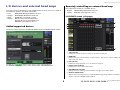
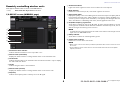
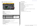
I/O DEVICE screen (I/O page)
1 +48V indicator
Indicates the phantom power (+48V) on/off status for each port.
2 GAIN knob
Indicates the gain of the head amp on the I/O device. This screen is only for display; the
value cannot be edited.
3 HPF indicator
Indicates the high-pass filter on or off status for each port.
4 Control status indicator
Indicates the control status of the device.
5 SYSTEM/SYNC indicators
Displays the error, warning, and information messages of the Dante device.
6 OUTPUT PATCH button
Appears when selecting a device (for I/O DEVICE) having a large number of channels.
Touch to open the OUTPUT PATCH window.
1
2
3
6
5
4

I/O devices and external head amps
V5.1 Supplementary Manual
4
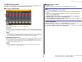
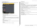
I/O DEVICE HA window
This screen is displayed when you select the desired I/O device in the I/O DEVICE screen
(I/O page). You can remotely control the head amp of the I/O device.
For Stagetec NEXUS(XDIP)
1
+48V button
These switch phantom power on/off for each channel.
2 GAIN knob
Indicates the gain of the head amp on the I/O device. To adjust the value, press the knob
to select it, and use the multifunction knobs (CL series) or the TOUCH AND TURN knob
(QL series).
NOTE
For devices with a wider setting range than the CL/QL series, since some values cannot be set
from the CL/QL series. Likewise, if the value set on the connected device side is outside the CL/
QL series setting range, it will be displayed as an approximate value or limit value.
3 FREQUENCY knob/HPF button
These controllers switch on or off the high-pass filter built into the head amp of the I/O
device, and adjust its cutoff frequency. If you press the FREQUENCY knob to select it,
you will be able to adjust it using the corresponding multifunction knob (CL series) or
the TOUCH AND TURN knob (QL series).
NOTE
For devices that differ in how the setting value changes from the CL/QL series, the cutoff
frequency will be set as an approximate value.
Remote control settings
• MTX/MRX series
The following settings are necessary to control the MTX/MRX series remotely.
• Stagetec NEXUS(XDIP)
Network configuration is required to control NEXUS(XDIP) remote. For details, please contact
the Stagetec Company, or refer to the website of the Stagetec Company.
Also, in order to validate the remote control setting contents from the CL/QL series, NEXUS
must be used to properly set the internal routing of XDIP.
1
2
3
STEP
1. Install the MTX-MRX Editor on the computer.
2. Connect the MTX-MRX series and Editor according to the MTX-MRX Editor user
guide.
3. Set remote (RS-232C) BIT RATE: 38400 in the System menu, Remote Control
dialog of the MTX-MRX Editor.
4. Match the subnet of the CL/QL series on the NETWORK screen (FOR DEVICE
CONTROL page) with the subnet of MTX-MRX series.
5. Place the ANALOG IN component using the MRX Designer, since the MRX Series
components can be freely placed therein.

I/O devices and external head amps
V5.1 Supplementary Manual
5
Remotely controlling wireless units
Now supports wireless units as remote controllable devices.
• Sony DWR-R03D DWX Digital Wireless Receiver
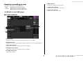
I/O DEVICE screen (WIRELESS page)
1 Connection status indicator
Indicates whether transmitter control is possible or not.
2 Channel name (transmitter)
Displays the channel name for setting channel names on the transmitter side.
3 TX.ATT knob
Indicates the gain value for the transmitter with a knob. This window is only for display;
the value cannot be edited.
4 TX.ATT
Indicates the gain value for the transmitter.
5 Channel name (receiver)
Displays the channel name for setting channel names on the receiver side.
6 Frequency
Indicates the frequency that is currently set for the RF signal.
7 Audio level indicator
Lights if the audio signal level of the receiver reaches the overload point.
8 MUTE indicator
Indicates the mute status (on/off) of the audio signal for the receiver.
9 Signal quality meter
Displays the quality of the received RF signal. The vertical axis represents quality and the
horizontal axis represents time, and the display of connection status is updated every
second. If you move away from the transmitter, or the quality of the RF signal decreases
due to the influence of disturbing radio waves, the bar graph becomes lower.
0 RF (Radio Frequency) signal meter
Shows bars to indicate the level of the RF signal. An active antenna indicator is shown
on the right side. It indicates which antenna is enabled. In the 4 Diversity mode, the one
with the strongest level among A to D is shown.
NOTE
For details about the relationship between the number of bars and the actual strength of the RF
signal, refer to the DWR-R03D manual.
A Battery indicator
Shows bars to indicate the remaining battery power.
B Control status indicator
Indicates the control status of the device.
NOTE
• When control on the receiver side is possible, the parameter values for the receiver are sent to
the console.
• As the number of remote control devices is increased at the same time, the meter update
frequency decreases.
1
2
4
3
6
5
8
7
:
9
A
B

I/O devices and external head amps
V5.1 Supplementary Manual
6
I/O DEVICE EDIT screen
This screen is displayed when you select the desired wireless device in the I/O DEVICE
screen (WIRELESS page). Here you can set the channel name and HA.
1 Connection status indicator
Indicates whether transmitter control is possible or not.
2 Channel name (transmitter)
Press this button to display the NAME screen for setting channel names on the
transmitter side.
3 TX.ATT knob
Sets the gain value for the transmitter. To adjust the value, touch the screen, then press
the knob to select it, and use the multifunction knobs (CL series) or the TOUCH AND
TURN knob (QL series). The knob will not display when the wireless device is not support
this control.
4 TX.ATT
Indicates the gain value for the transmitter.
5 Channel name (receiver)
Press this button to display the NAME screen for setting channel names on the receiver
side.
6 Frequency
Indicates the frequency that is currently set for the RF signal.
7 RX.LEVEL meter
Indicates the input level for the receiver.
8 MUTE button
Mutes the audio signal for the receiver.
9 Signal quality meter
Displays the quality of the received RF signal. The vertical axis represents quality and the
horizontal axis represents time, and the display of connection status is updated every
second. If you move away from the transmitter, or the quality of the RF signal decreases
due to the influence of disturbing radio waves, the bar graph becomes lower.
0 RF (Radio Frequency) signal meter
Shows bars to indicate the level of the RF signal. An active antenna indicator is shown
on the right side. It indicates which antenna is enabled. In the 4 Diversity mode, the one
with the strongest level among A to D is shown.
NOTE
For details about the relationship between the number of bars and the actual strength of the RF
signal, refer to the DWR-R03D manual.
A Battery indicator
Shows bars to indicate the remaining battery power.
B Mode indicator
Indicates the mode status of the device such as 4 Diversity mode. When not activated,
it shows “4 Diversity mode: off” respectively.
C PORT ASSIGN tab
Select these tabs to switch between the windows that specify the ports where the actual
input signals are assigned.
1
2
3
4
5
6
7
8
9
:
A
C
B

I/O devices and external head amps
V5.1 Supplementary Manual
7
Remotely controlling an amp
Now supports the remote controllable devices.
• NEXO NXAMPmk2 Powered TD Controller
• Yamaha DZR- D series Powered Loudspeakers
DXS XLF-D series Powered Subwoofers
I/O DEVICE screen (AMP page)
For NEXO NXAMPmk2
1
Channel name
Displays the channel name (the speaker preset name for the NXAMP).
2 Output level meter
Displays the level of Voltage (amplifier output) and the level of Protect (gain reduction).
3 LIMIT status indicator
Lights when the limiter for amplifier protection is applied.
4 PROTECT status indicator
Lights when the limiter for speaker protection is applied.
5 VOLUME setting value
Displays the volume.
6 MUTE indicator
Indicates the currently set mute status.
7 Control status indicator
Indicates the control status of the device.
8 Device status indicator
Indicates the status of the device.
1
2
4
3
6
5
8
7

I/O devices and external head amps
V5.1 Supplementary Manual
8
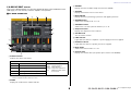
I/O DEVICE EDIT screen
This screen is displayed when you select the desired I/O device in the I/O DEVICE screen
(AMP page). You can remotely control the amplifier or the speakers.
For NEXO NXAMPmk2
1
STATUS indicator
Indicates the status of the device.
* ALERT indicator display is green and red only. When an alert occurs, the indicator turns red and the alert
contents are displayed at the bottom of the screen.
2 SCENE
Displays the recalled scene number and title.
3 CABINET
Displays the name of NEXO Setup selected in the NXAMP.
4 VERSION
Displays the firmware version of the device.
5 INPUT METER
Displays both the input analog input levels and digital input levels.
6 STANDBY button
Switches the standby mode on or off.
7 OVERMUTE button
Switches the over mute (mute all channels) on or off.
8 Output level meter
Displays the output level of the channel.
9 VOLUME knob
Sets the channel volume.
0 LIMIT indicator
Lights while the limiter for amplifier or power supply protection is applied.
A PROTECT indicator
Lights while the limiter for speaker protection is applied.
B MUTE button
Switches the channel mute on or off.
C Channel name
Displays the channel name (the speaker preset name for the NXAMP).
Status Indicator display
OVERALL Overall status of the device
Green: Normal operation
Yellow: Fault detection
Orange: Temporary malfunction
Red: Malfunction that cannot
be resolved
ALERT Alert
AMP Operating status of each amplifier channel
PS Operating status of power supply unit
FAN Operating status of each FAN unit
9
C
A
:
6
7
1
8
2
B
5
3 4

I/O devices and external head amps
V5.1 Supplementary Manual
9
For Yamaha DZR-D series, DXS XLF-D series
1
PRESET
Displays the set preset number and title.
2 VERSION
Displays the firmware version of the device.
3 STATUS indicator
Indicates the status of the device.
* ALERT indicator display is green and red only. When an alert occurs, the indicator turns red and the alert
contents are displayed at the bottom of the screen.
4 INPUT meter
Displays both the input analog input levels and digital input levels.
5 HPF ON button (DZR-D series only)
Switches the HPF on or off. The LPF is hidden and always on.
6 HPF/LPF FREQUENCY knob
Sets the HPF frequency for DZR-D series or the LPF frequency for DXS XLF-D series.
7 EQ ON button
Switches the EQ on or off.
8 DELAY ON button
Switches the delay on or off.
9 DELAY knob
Sets the delay time.
0 DELAY TIME
Displays the delay time by time (TIME) and distance (meter, feet).
A Output level meter
Displays the output level of the speakers.
B MASTER LEVEL knob
Sets the output level.
C LIMIT indicator
Lights while the limiter for amplifier or power supply protection is applied.
D MUTE button
Switches the mute on or off.
E Channel name
Displays the channel name (the LABEL for the DZR).
Status Indicator display
OVERALL Overall status of the device
Green: Normal operation
Yellow: Fault detection
Orange: Temporary malfunction
Red: Malfunction that cannot
be resolved
ALERT Alert
AMP Operating status of each amplifier channel
PS
Operating status of power supply unit
3
1
2 5 8
4
7 :6 9 B
A
D
E
C

© 2018 Yamaha Corporation
Published 11/2018 MA-A1
Manual Development Group
Yamaha Downloads
https://download.yamaha.com/
Yamaha Pro Audio global website
http://www.yamahaproaudio.com/
-
 1
1
-
 2
2
-
 3
3
-
 4
4
-
 5
5
-
 6
6
-
 7
7
-
 8
8
-
 9
9
-
 10
10


diğer dillerde
- español: Yamaha V5 Manual de usuario
- français: Yamaha V5 Manuel utilisateur
- italiano: Yamaha V5 Manuale utente
- svenska: Yamaha V5 Användarmanual
- čeština: Yamaha V5 Uživatelský manuál
- polski: Yamaha V5 Instrukcja obsługi
- Deutsch: Yamaha V5 Benutzerhandbuch
- português: Yamaha V5 Manual do usuário
- English: Yamaha V5 User manual
- dansk: Yamaha V5 Brugermanual
- русский: Yamaha V5 Руководство пользователя
- suomi: Yamaha V5 Ohjekirja
- Nederlands: Yamaha V5 Handleiding
- română: Yamaha V5 Manual de utilizare