
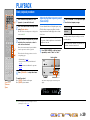
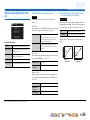
Owner’s Manual
AV Receiver English

En 2
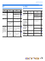
CONTENTS
INTRODUCTION
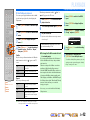
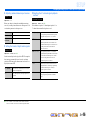
Features and capabilities ...................................................3
About this manual............................................................. 4
Supplied accessories......................................................... 4
Part names and functions.................................................. 5
Front panel........................................................................5
Rear panel.........................................................................6
Front panel display ........................................................... 7
Remote control .................................................................8
CONNECTIONS
Connecting speakers ..........................................................9
Speaker channels and functions........................................ 9
Speaker layout ................................................................ 10
Connecting speakers and subwoofer ..............................11
Connecting external components....................................14
Cable plugs and jacks .....................................................14
Connecting a TV monitor...............................................15
Connecting BD/DVD players and other devices............18
Connecting video cameras and portable audio players .. 22
Transmitting input A/V to external components ............ 22
Connecting the FM/AM antennas ..................................23
Set up the speaker parameters automatically
(YPAO) .............................................................................. 24
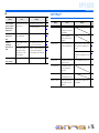
PLAYBACK
Basic playback procedure ...............................................29
Adjusting high/low-frequency sound (Tone control) ..... 29
Changing input settings with a single key
(SCENE function) ............................................................30
Registering input sources/sound field program .............. 30
Enjoying sound field programs....................................... 30
Selecting sound field programs and sound decoders...... 30
Sound field programs .....................................................33
FM/AM tuning ................................................................. 35
Selecting a frequency for reception (Normal tuning)..... 35
Registering and recalling a frequency (Preset tuning) ... 36
Recalling a preset station................................................ 38
Clearing preset stations .................................................. 38
Radio Data System tuning
(U.K. and Europe models only) ..................................... 38
Playing back tunes from your iPod™/iPhone™ ........... 40
Connecting the Yamaha iPod universal dock ................. 40
Controlling an iPod™/iPhone™ .................................... 40
Playing back tunes from Bluetooth™ components....... 43
Connecting a Yamaha Bluetooth wireless audio
receiver ........................................................................... 43
Pairing Bluetooth™ components ................................... 43
Using Bluetooth™ components ..................................... 44
SETUP
Configuring the settings specific for each input source
(Option menu) .................................................................. 45
Option menu display and setup ...................................... 45
Option menu items ......................................................... 45
Setting various functions (Setup menu)......................... 49
Setup menu display and settings .................................... 49
Setup menu items ........................................................... 50
Manages settings for speakers........................................ 50
Setting the audio output function of this unit................. 54
Setting HDMI functions ................................................. 55
Making the receiver easier to use ................................... 58
Setting the sound field program ..................................... 59
Prohibiting setting changes ............................................ 59
Setting sound field program parameters ....................... 60
CINEMA DSP parameters ............................................. 61
Parameters usable in certain sound field programs ........ 61
Parameters usable in surround decoder .......................... 62
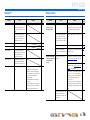
Controlling other components with the remote
control ............................................................................... 63
Keys connecting external components ........................... 63
Default remote control code settings.............................. 63
Registering remote control codes for external
component operations .................................................... 64
Resetting all remote control codes ................................. 65
Extended functionality that can be configured
as needed (Advanced Setup menu) ................................ 66
Displaying/Setting the Advanced Setup menu............... 66
Setting the impedance of speakers
(U.S.A. and Canada models only).................................. 66
Avoiding crossing remote control signals when using
multiple Yamaha receivers ............................................. 66
High quality playback using bi-amplification
connections .................................................................... 67
Removing HDMI video output up-scaling limits .......... 67
Changing FM/AM frequency steps
(Asia and General models only)..................................... 67
Initializing various settings for this unit ........................ 67
Using the HDMI Control function ................................. 68
APPENDIX
Troubleshooting ............................................................... 71
General........................................................................... 71
HDMI™ ......................................................................... 74
Tuner (FM/AM) ............................................................. 74
iPod™/iPhone™ ............................................................ 75
Bluetooth™.................................................................... 76
Remote control............................................................... 76
Glossary............................................................................ 77
Audio information.......................................................... 77
Sound field program information................................... 78
Video information .......................................................... 78
Information on HDMI™................................................. 79
About trademarks ........................................................... 79
Specifications.................................................................... 80
Index ................................................................................. 82

En 3
INTRODUCTION
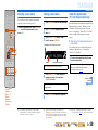
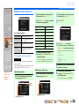
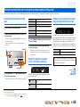
■ Built-in high-quality, high-power 7-channel amplifier
■ 1-button input/sound field program switching (SCENE function) .......................30
■ Speaker connections for 2- to 7.1-channel configurations
– (U.S.A. and Canada models only) Speaker impedance configuration.....................................................12
– Speaker channels and functions .................................................................................................................9
– Speaker layout..........................................................................................................................................10
– Speaker cable connection.........................................................................................................................11
– Subwoofer cable connection ....................................................................................................................13
– High quality playback using bi-amplification connections .....................................................................13
■ Acoustic parameter adjustment to match your speakers and listening
environment
– Automatic settings for speaker acoustic parameters
(YPAO - Yamaha Parametric Room Acoustic Optimizer).......................................................................24
– Specifying the settings for each speaker ..................................................................................................50
– Volume control for each speaker..............................................................................................................52
– Speaker distance settings .........................................................................................................................52
– Sound quality control with the equalizer <Graphic Equalizer> ..............................................................52
– Test tone speaker adjustment ...................................................................................................................53
– Bass and treble level adjustment <Tone Control> ...................................................................................29
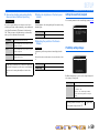
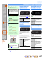
■ External component connection (max. 14 inputs) and playback
– External component connection...............................................................................................................15
– Audio signal output from the TV transmitted through the HDMI jack ...................................................57
– HDMI/AV video input combining other audio input...............................................................................47
– Correction of lag between audio and video signals <Lipsync>...............................................................54
– Protective cover for front panel jacks ........................................................................................................4
– Input source name changing <Input Rename> ........................................................................................58
– Configuring the settings specific for each input source <Option menu> ................................................45
– Playback from external components........................................................................................................29
– Playback from an iPod/iPhone (iPod/iPhone and components sold separately) .....................................40
– Playback from a Bluetooth component (Bluetooth and components sold separately) ............................43
■ HDMI settings
– Setting the HDMI functions.....................................................................................................................55
– Controlling this unit from HDMI compatible device such as TVs <HDMI Control function> ..............68
– Listening to TV audio with single HDMI cable connection <Audio Return Channel function>............70
– Changing HDMI video output up-scaling resolution ..............................................................................57
– Removing HDMI video output up-scaling limits ....................................................................................67
■ FM/AM tuner
– FM/AM broadcast listening .....................................................................................................................35
– Simple preset tuning ................................................................................................................................36
– (U.K. and Europe models) Radio Data System tuning ............................................................................38
– (U.K. and Europe models) Automatic traffic information reception.......................................................39
– Changing FM mode (Stereo/Monaural)...................................................................................................36
– (Asia and General models only) Changing FM/AM frequency steps initializing various settings
for this unit...............................................................................................................................................35
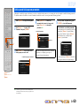
■ Multi-channel, multi-format playback
– Sound field effect selection......................................................................................................................30
– Playback without sound field effects .......................................................................................................31
– Stereo playback........................................................................................................................................31
– Sound field effect configuration ..............................................................................................................60
– Compressed-music playback ...................................................................................................................30
– Setting the decode format of digital audio signals <Decoder Mode> .....................................................46
– Selecting the 5.1-channel signal playback method <Extended Surround> .............................................46
■ Front panel information display/OSD (On-Screen Display) on the TV screen
– Front panel display information switching ................................................................................................7
– Front panel display brightness adjustment <Dimmer>............................................................................59
– Adjusting the position of the on-screen display <OSD Shift> ................................................................59
– Digital video/audio signal information display <Signal Info> ................................................................47
■ Volume adjustment functions
– Easy listening at low volumes <Adaptive DRC> ....................................................................................54
– Maximum volume settings.......................................................................................................................55
– Startup volume settings............................................................................................................................55
– Adjusting volume between input sources <Volume Trim> .....................................................................46
■ Remote control operation
– External component operation with this unit’s remote control................................................................63
– Multiple Yamaha receiver operation without signal interference <Remote ID Switching>....................66
■ Other features
– Standby mode after prolonged non-operation <Auto Power Down function>........................................59
– Standby mode after a specific amount of time <Sleep timer>...................................................................8
– To charge the iPod/iPhone when this unit is in standby mode <iPod Standby Charge> .........................42
– Initializing various settings for this unit ..................................................................................................67
– Prohibiting setting changes of this unit <Memory Guard> .....................................................................59
Features and capabilities

En 4
INTRODUCTION
Features and capabilities
About this manual
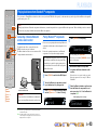
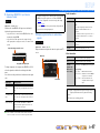
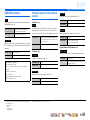
Supplied accessories
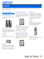
Check that you received all of the following parts.
• Remote control
• Batteries (AAA, R03, UM-4) x 2
• YPAO microphone
• AM loop antenna
• Indoor FM antenna
• VIDEO AUX input cover
• Some features are not available in certain regions.
• This manual is created prior to production. Design and
specifications are subject to change in part as a result of
improvements, etc. In case of differences between the manual and
product, the product has priority.
• “
dHDMI1” (example) indicates the name of the parts on the
remote control. Refer to the “Part names and functions” (☞
p. 5)
for the information about each position of the parts.
• J
1 indicates that the reference is in the footnote. Refer to the
corresponding numbers on the bottom of the page.
• ☞
indicates the page describing the related information.
• Click on the “ ” at the bottom of the page to display the
corresponding page in “Part names and functions.”
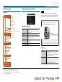
Front panel
Rear panel
Front panel display
Remote control
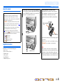
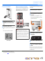
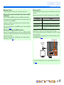
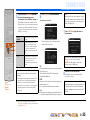
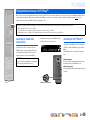
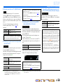
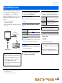
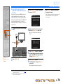
■ Attaching the VIDEO AUX input cover (supplied)
To protect against dust, attach the supplied VIDEO AUX input
cover to the VIDEO AUX jacks when you do not use the jacks.
To remove the cover, push the left section of it.
Attach the cover
PUSH
Remove the cover
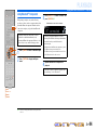
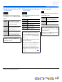
■ Installing batteries in the remote control
When inserting batteries in the remote control, remove the
battery compartment cover from the reverse side of the remote
control, and insert two AAA batteries into the battery
compartment so that they match with the polarity markings (+
and -).
Replace the batteries with new ones if the following symptoms
become evident:
• The remote control can only be operated within a narrow range.
•
bTRANSMIT does not light up, or only lights dimly.
NOTE
If there are remote control codes for external components
registered to the remote control, removing the batteries for more
than 2 minutes, or leaving exhausted batteries in the remote
control, may clear the remote control codes. If this should occur,
replace the batteries with new ones, and set the remote control
codes.
a
c
b
Battery compartment
cover
Battery compartment

En 5
INTRODUCTION
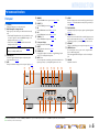
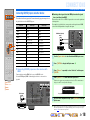
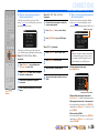
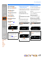
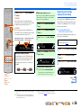
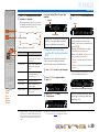
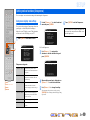
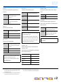
Front panel
a A (Power)
Switches this unit between on and standby mode.
b HDMI Through/iPod Charge indicator
Lights up in any of the following cases while the unit is in standby
mode.
• When Standby Through function is enabled and audio/video from
an external component connected with HDMI is output to a TV
during the standby mode (☞
p. 56). J1
• When an iPod is charging in the Yamaha iPod universal dock
during the standby mode (☞
p. 42).
c YPAO MIC jack
Connect the supplied YPAO microphone and adjust the speaker
balance automatically (☞
p. 24).
d INFO
Changes the information displayed on the front panel display (☞
p. 7).
e MEMORY
Registers FM/AM stations as preset stations (☞
p. 37). J2
f PRESET j / i
Selects an FM/AM preset station (☞
p. 38). J2
g FM
Sets the FM/AM tuner band to FM (☞
p. 35). J2
h AM
Sets the FM/AM tuner band to AM (☞
p. 35). J2
i TUNING jj / ii
Changes FM/AM tuner frequencies (☞
p. 35). J2
j Front panel display
Displays information on this unit (☞
p. 7).
k DIRECT
Switches this unit to direct mode (☞
p. 32).
l PHONES jack
For plugging headphones in. Sound effects applied during playback
can also be heard through the headphones.
m INPUT l / h
Selects an input source from which to playback. Press either the left or
right key repeatedly to cycle through the input sources in order.
n SCENE
Switches the input source and the sound field program with a single
button (☞
p. 30). When this unit is in standby mode, press this key to
switch on.
o TONE CONTROL
Adjusts high-frequency/low-frequency output of speakers/headphones
(☞
p. 29).
p PROGRAM l / h
Switches between the sound field effect (sound field program) you are
using and the surround sound decoder (☞
p. 30). Press either the left
or right key repeatedly to cycle through the input sources in order.
q STRAIGHT
Changes a sound field program to straight decoding mode (☞
p. 31).
r VIDEO AUX jacks
For connecting video cameras, game consoles, and portable music
players to this unit temporarily.
Attach the supplied VIDEO AUX input cover when not using this
jack.
s VOLUME
Adjusts the volume level.
Part names and functions
When the HDMI Control functions are “On” (☞p. 56), then
this stays on during standby mode.
VIDEO
AUX
PHONES
SILENT
CINEMA
TONE
CONTROL
STRAIGHT
VOLUME
TV
BD
DVD
CD
RADIO
INPUT
PROGRAM
SCENE
VIDEO
AUDI O
PORTABLE
LR
INFO
MEMORY
PRESET
FM AM
TUNING
YPAO MIC DIRECT
o qm p
a
nl s
c
r
j
d gf h ke i
b
J
1 : During the standby mode, you can select the HDMI input (HDMI1-4) to output to a TV. When the input is changed correctly, HDMI Through/iPod Charge indicator blinks twice.
J
2 : Usable when you have selected tuner input.

En 6
INTRODUCTION
Part names and functions
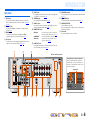
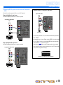
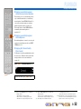
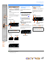
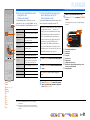
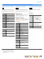
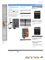
Rear panel
a DOCK jack
For connecting an optional Yamaha iPod universal dock (such as
YDS-12) or Bluetooth wireless audio receiver (YBA-10) (☞
p. 40,
☞
p. 43).
b HDMI OUT jack
For connecting an HDMI - compatible TV to output audio/video
signals (☞
p. 16).
c HDMI1-4 jacks
For connecting external components equipped with HDMI-
compatible outputs to receive audio/video signals (☞
p. 18).
d AV1-6 jacks
For connecting to external components equipped with audio/video
outputs to receive audio/video signals (☞
p. 19, p. 20).
e AV OUT jacks
For outputting audio/video signals received when analog inputs (AV3-
6 or AUDIO1-2) are selected (☞
p. 22).
f ANTENNA jacks
For connecting AM and FM antennas (☞
p. 23).
g AUDIO1-2 jacks
For connecting to external components equipped with analog audio
outputs to input sound into this unit (☞
p. 21).
h MONITOR OUT jacks
i AUDIO OUT jacks
For outputting audio signals received when analog jacks, such as the
AV5-6 or AUDIO1-2 are selected (☞
p. 22).
j SPEAKERS terminals
For connecting the front, center, surround and surround back speakers
(☞
p. 12).
k SUBWOOFER jack
For connecting a subwoofer with a built-in amplifier (☞
p. 13).
l VOLTAGE SELECTOR
(Asia and General models only)
Select the switch position according to your local voltage (Refer to
Quick Reference Guide).
m Power cable
For connecting this unit to an AC wall outlet.
VIDEO jack For connecting a TV capable of receiving video
input, and outputting video signals to it (☞p. 16).
COMPONENT
VIDEO jacks
For connecting TV that are compatible with
component video signals, using three cables to
output video signal (☞p. 16).
COMPONENT
VIDEO
P
R
P
B
Y
OPTICAL OPTICAL
(
TV
)
AV
1
AV
2
AV
3
AV
4
AV
5
AV
6
AUD
IO 1
AUDIO 2
COAXIAL COAXIAL
(
CD
)
CENTER
SURROUND
SINGLE
SURROUND BACK/
BI-AMP
(
BD/DVD
)
HDMI 2HDMI 1 HDMI 3
HDMI 4
FRONT
HDMI
OUT
AV
OUT
SUBWOOFER
AUDIO
PRE OUT
OUT
VIDEO
DOCK
ARC
S VIDEO
ANTENNA
FM
75ǡ
GND
AM
MONITOR OUT
COMPONENT
VIDEO
VIDEO
SPEAKERS
P
R
P
B
Y
HDMI
OUT
AV
OUT
SUBWOOFER
AUDIO
PRE OUT
OUT
ARC
COMPONENT
VIDEO
VIDEO
P
R
P
B
Y
5
AV 6
AUD
IO 1
AUD
IO 2
C
ENTE
R
S
URR
O
UND
S
IN
G
L
S
URROUND BACK/
BI
-
AMP
(
BD/DVD
)
HDMI 2
HDMI 1
HDMI
3
HDMI
4
F
R
O
N
T
D
E
O
ANTENNA
FM
7
5
ǡ
GN
D
AM
SPEAKERS
c
ekgij
d h
ba
m
l
f
Distinguishing the input and output jacks
The area around the audio/video output jacks is
marked in white to prevent connection errors. Use
these jacks to output audio/video signals to a TV or
other external component.
Output jacks
(Ex: U.K. and Europe models)

En 7
INTRODUCTION
Part names and functions
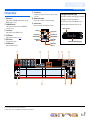
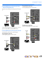
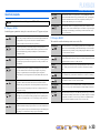
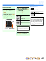
Front panel display
a HDMI indicator
Lights up during normal HDMI communication when any of the
HDMI 1-4 inputs are selected.
b CINEMA DSP indicator
Lights up when a sound field effect that uses CINEMA DSP
technology is selected.
c Tuner indicator
Lights up when receiving an FM/AM broadcast.
d SLEEP indicator
Lights up when the sleep timer is on (☞
p. 8).
e MUTE indicator
Flashes when audio is muted.
f VOLUME indicator
Displays the current volume level.
g Cursor indicators
Light up if corresponding cursors on the remote control are available
for operations.
h Multi information display
Displays a range of information on menu items and settings.
i Speaker indicators
Indicate speaker terminals from which signals are output.
SW
C
LR
SL SR
SBL SBRSB
Front speaker L
Surround speaker L
Subwoofer
Front speaker R
Surround speaker R
Center speaker
Surround back
speaker L
Surround back
speaker R
Surround back
speaker J1
■ Changing the front panel display
The front panel can display sound field programs and surround
decoder names as well as the active input source.
Press fINFO repeatedly to cycle through input source →
sound field program → surround decoder in order. J2
SW
C
L
SL SR
R
SBL SBR
Straight
HDMI1
VOL.
Input source name
Sound field program (DSP program)
STEREO
SLEEP
VOL.
TUNED
SW
C
LR
SL SR
MUTE
SBL SBRSB
abcdfe
gh ig
J
1 : “SB” is displayed when using a 6.1-channel configuration only.
J
2 : While selecting a tuner input, the FM/AM frequency is displayed instead of the input source.

En 8
INTRODUCTION
Part names and functions
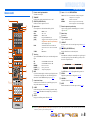
Remote control
a Remote control signal transmitter
Transmits infrared signals.
b TRANSMIT
Lights up when a signal is output from the remote control.
c SOURCE A (SOURCE Power)
Switches an external component on and off.
d Input selector
Select an input source on this unit from which to playback.
e Tuner keys
Operates the FM/AM tuner. These keys are used when using the tuner
input.
f INFO
Cycles the information displayed on the front panel display (the name
of the currently selected input source, the sound field program, the
surround decoder, the FM/AM tuner frequency, etc.)(☞
p. 7).
g Sound selection keys
Switch between the sound field effect (sound field program) you are
using and the surround decoder (☞
p. 30).
h SCENE
Switches the input source and the sound field program with a single
button (☞
p. 30). When this unit is in standby mode, press this key to
switch on.
i SETUP
Displays a detailed Setup menu for this unit (☞
p. 49).
j Cursor B / C / D / E, ENTER, RETURN
k External component operation keys
Operate recording, playback, and menu displays etc. for external
components. J1
l Numeric keys
Enter numbers.
m TV control keys
Operate a monitor such as a TV.
n CODE SET
Sets remote control codes for external component operations (☞
p. 63,
p. 67
).
o RECEIVER A (RECEIVER Power)
Switches this unit between on and standby mode.
p SLEEP
Switch this unit to standby mode automatically after a specified period
of time has elapsed (sleep timer). Press this key repeatedly to set the
time for the sleep timer function.
The SLEEP indicator (☞
p. 7) lights up when the sleep timer is on.
q OPTION
Displays the Option menu for each input source (☞
p. 45).
r VOLUME +/-
Adjusts the volume level (☞
p. 29).
s MUTE
Turns the mute function of the sound output on and off (☞
p. 29).
RECEIVER
SCENE
OPTION
SETUP
RETURN
VOLUME
ENHANCER
SUR. DECODE
STRAIGHT DIRECT
HDMI
AV
AUDIO
TRANSMIT
SLEEP
1234
1234
1256
V-AU X
TUNER
FM
INFO
MEMORY
AM
PRESET
TUNING
MOVIE MUSIC
STEREO
BD
DVD
TV
CD
RADIO
MUTE
ENTER
7 856
90
10
1234
REC
ENT
TV
TV VOL TV CH
TOP
MENU
POP-UP
MENU
DISPLAY
SOURCE
CODE SET
INPUT
MUTE
DOCK[ A ] [ B ]
a
c
b
p
o
d
e
g
h
i
q
r
s
l
m
n
j
f
k
HDMI1-4 HDMI1-4 jacks
AV1-6 AV1-6 jacks
AUDIO1-2 AUDIO1-2 jacks
V-AUX Front panel VIDEO AUX jacks
[A]/[B] Changes the external component to operate with
the kExternal component operation keys
without changing inputs. J1
DOCK A Yamaha iPod universal dock or Bluetooth
wireless audio receiver connected to the DOCK
jack.
TUNER FM/AM tuner
FM Sets the FM/AM tuner band to FM.
AM Sets the FM/AM tuner band to AM.
MEMORY Presets radio stations.
PRESET F / G Selects a preset station.
TUNING H / I Changes tuning frequencies.
Cursor B / C / D / E Select menu items and change settings when
setting menus, etc, are displayed.
ENTER Confirms a selected item.
RETURN Returns to the previous screen when setting
menus are displayed, or ends the menu display.
Sleep 120min. Sleep 90min.
Sleep 60min.Sleep 30min.Sleep Off
JJ
1 : You can use kExternal component operation keys for each input source to operate registered components. Remote control codes must be registered for each input
in advance if you want to operate external components (☞
p. 63).

En 9
CONNECTIONS
This unit uses acoustic field effects and sound decoders to bring you the impact of a real movie theater or concert hall. These effects will be brought to you with ideal speaker positioning and
connections in your listening environment.
Speaker channels and functions
■
Front left and right speakers
The front speakers are used for the front channel sounds (stereo
sound) and effect sounds.
Front speaker layout:
Place these speakers at an equal distance from the ideal listening
position in the front of the room. When using a projector screen,
the appropriate top positions of the speakers are about 1/4 of the
screen from the bottom.
■
Center speaker
The center speaker is for the center channel sounds (dialog, vocals,
etc.).
Center speaker layout:
Place it halfway between the left and right front speakers. When
using a TV, place the speaker just above or just under the center of
the TV with the front surfaces of the TV and the speaker aligned.
When using a screen, place it just under the center of the screen.
■
Surround left and right speakers
The surround speakers are for effect and vocal sounds with the 5.1-
channel speakers providing rear-area sounds. When used with 6.1/
7.1-channel (including surround back channel), sound for right and
left rear-area is output.
Surround speaker layout:
Place the speakers at the rear of the room on the left and right sides
facing the listening position. They should be placed between 60
degrees and 80 degrees from the listening position and with the
speaker tops at a height of 1.5 – 1.8 m from the floor.
■
Surround back left and right speakers
Outputs the rear effect. When used with 6.1ch sound, sound from
the left and right sound surround back speakers is mixed and output
from a single speaker. When used with 5.1ch sound, sound from
surround back speakers is distributed between the left and right
surround speakers.
Surround back speaker setting:
When used with 7.1ch sound, arrange the left and right speakers
towards the listening position, to the rear of the listening position.
Arrange the left and right speakers at least 30 cm apart. The same
separation as with the front left and right speakers is optimum.
When used with 6.1ch sound, arrange these to the rear of the
listening position.
■
Subwoofer
The subwoofer speaker is used for bass sounds and low-frequency
effect (LFE) sounds included in Dolby Digital and DTS. Use a
subwoofer that is equipped with built-in amplifier.
Subwoofer speaker layout:
Place it exterior to the front left and right speakers facing slightly
inward to reduce echoes from the wall.
Connecting speakers
Ex.
Ex.
Ex.
Ex.
Ex.

En 10
CONNECTIONS
Connecting speakers
Speaker layout
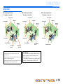
■ 7.1-channel speaker layout
(7 speakers + subwoofer)
■ 6.1-channel speaker layout
(6 speakers + subwoofer)
■ 5.1-channel speaker layout
(5 speakers + subwoofer)
• Connect at least two speakers (front left and right).
• If you cannot connect all five speakers, give priority to the
surround speakers.
• The surround speakers should be placed between 60 degrees and
80 degrees from the listening position.
• When used with 7.1-channel speaker layout, arrange the left and
right surround back speakers at least 30 cm a part.
60q
60q
80q
80q
Front speaker L
Front speaker R
Subwoofer
Center speaker
Surround speaker L
Surround
speaker R
Surround back
speaker R
Surround back
speaker L
30 cm (12 in)
or more
■ CRT monitors
We recommend that you use magnetically shielded speakers to
avoid video distortion, especially for the front and center
speakers near the screen.
If your screen still gets interference from magnetically shielded
speakers, move the speakers farther away from your TV.
60q
60q
80q
80q
Front speaker L
Front speaker R
Subwoofer
Center speaker
Surround speaker L
Surround
speaker R
Surround back
speaker
60q
60q
80q
80q
Front speaker L
Front speaker R
Subwoofer
Center speaker
Surround speaker L
Surround
speaker R

En 11
CONNECTIONS
Connecting speakers
Connecting speakers and subwoofer
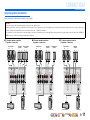
Connect your speakers to their respective terminals on the rear panel.
■ 7.1-channel speaker connection
(7 speakers + subwoofer)
■ 6.1-channel speaker connection
(6 speakers + subwoofer)
■ 5.1-channel speaker connection
(5 speakers + subwoofer)
CAUTION
• Remove the AC power cable of this unit from the power outlet before connecting the speakers.
• Generally speaker cables consist of two parallel insulated cables. One of these cables is a different color, or has a line running along it, to indicate different polarity. Insert the different colored (or lined) cable into the “+”
(positive, red) terminal on this unit and the speakers, and the other cable into the “-” (negative, black) terminal.
• Be careful that the core of the speaker cable does not touch anything or come into contact with the metal areas of this unit. This may damage this unit or the speakers. If the speaker cables short circuit, “CHECK SP
WIRES!” will appear on the front panel display when this unit is switched on.
CENTER
SURROUND
SINGLE
SURROUND BACK/
BI-AMP
HDMI 3
HDMI 4
FRONT
SUBWOOFER
AUDI O
PRE OUT
OUT
SPEAKERS
SubwooferCenter speaker
Front speaker Surround
speaker
Surround back
speaker
RL
RL RL
CENTER
SURROUND
SINGLE
SURROUND BACK/
BI-AMP
HDMI 3
HDMI 4
FRONT
SUBWOOFER
AUDI O
PRE OUT
OUT
SPEAKERS
SubwooferCenter speaker
Front speaker Surround
speaker
Surround back
speaker
RL
RL
CENTER
SURROUND
SINGLE
SURROUND BACK/
BI-AMP
HDMI 3
HDMI 4
FRONT
SUBWOOFER
AUDI O
PRE OUT
OUT
SPEAKERS
SubwooferCenter speaker
Front speaker Surround
speaker
RL
RL

En 12
CONNECTIONS
Connecting speakers
■
(U.S.A. and Canada models only)
Changing speaker impedance
This unit is configured for 8Ω speakers as the factory setting.
When connecting to 6Ω speakers, carry out the following
procedure to switch to 6Ω.
1
Switch this unit to the standby mode.
2
Press A while pressing and holding STRAIGHT on
the front panel.
Release the keys when “ADVANCED SETUP” is displayed on
the front panel display.
After approximately a few seconds, the top menu items are
displayed. J1
3
Check that “SP IMP.” is displayed on the front panel.
4
Press STRAIGHT repeatedly to select a “6ΩMIN.”
5
Switch this unit to the standby mode, and then
switch it on again.
The power turns on, when the settings you made has been
configured.
■
Connecting speakers
1
Remove approximately 10 mm of insulation from the
ends of the speaker cables, and twist the bare wires
of the cables together firmly so that they will not
cause short circuits.
2
Loosen the speaker terminals.
3
Insert the bare wire of the speaker cable into the gap
on the side of the terminal.
4
Tighten the terminal.
PHONES
SILENT
CINEMA
TONE
CONTROL
STRAIGHT
TV
BD
DVD
CD
RADIO
INPUT
PROGRAM
SCENE
INFO
MEMORY
PRESET
FM AM
YPAO MIC
STRAIGHT
PROGRAM l / h
A
SPIMP.-8MIN
FRONT
2
2
3
1
4
4
Connecting the banana plug (Except U.K., Europe,
Asia and Korea models)
Tighten the knob, and then insert the banana plug into the end of
the terminal.
FRONT
Banana plug
JJ
1 : Refer to the “Extended functionality that can be configured as needed
(Advanced Setup menu)” (☞
p. 66) for details on the Advanced Setup menu.

En 13
CONNECTIONS
Connecting speakers
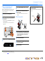
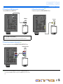
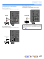
■
Connecting the subwoofer
1
Connect the subwoofer input jack to the
SUBWOOFER jack on this unit with an audio pin
cable.
2
Set the subwoofer volume as follows.
Volume: Set to approximately half volume (or slightly less than
half).
Crossover frequency (if available): Set to maximum.
■
Bi-amp connection for front speakers
This unit can connect speakers that support bi-amp connections.
When connecting speakers, connect the FRONT jacks and the
SURROUND BACK/BI-AMP jacks as in the diagram below.
To activate a bi-amp connection, connect the power cable, and then
set the following.
1
Check that the unit power is in standby mode.
2
Press A while pressing and holding STRAIGHT on
the front panel.
Release the keys when “ADVANCED SETUP” is displayed on
the front panel display. After approximately a few seconds, the
top menu items are displayed. J1
3
Press PROGRAM h repeatedly to switch to the
following display.
4
Press STRAIGHT to change the settings to “ON.”
5
Switch this unit to standby mode, and then switch it
on again.
The bi-amp connection becomes effective and the unit is powered on.
To deactive a bi-amp connection, follow the same procedure and
select “OFF” in step 4.
VOLUME
MIN MAX
CROSSOVER/
HIGH CUT
MIN MAX
Subwoofer examples
NOTES
• Before making bi-amplification connections, remove any
brackets or cables that connect a woofer with a tweeter. Refer to
the instruction manuals of speakers for details. When not making
bi-amplification connections, make sure that the brackets or
cables are connected before connecting the speaker cables.
• If connecting a bi-amp, then surround back speakers cannot be
used.
FRONT
SURROUND BACK/
BI-AMP
PHONES
SILENT
CINEMA
TONE
CONTROL
STRAIGHT
TV
BD
DVD
CD
RADIO
INPUT
PROGRAM
SCENE
INFO
MEMORY
PRESET
FM AM
YPAO MIC
STRAIGHT
PROGRAM l / h
A
BI-AMP-OFF
JJ
1 : Refer to the “Extended functionality that can be configured as needed
(Advanced Setup menu)” (☞
p. 66) for details on the Advanced Setup menu.

En 14
CONNECTIONS
Cable plugs and jacks
This unit is equipped with the following input/output jacks. Use jacks and cables appropriate for
components that you are going to connect.
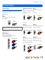
■
Audio/Video jacks
HDMI jacks
Digital video and digital sound are transmitted through a single jack.
Only use an HDMI cable.
■
Analog video jacks
■
Audio jacks
Connecting external components
• Use a 19-pin HDMI cable with the HDMI logo.
• We recommend using a cable less than 5.0 m long to prevent signal quality degradation.
COMPONENT VIDEO jacks
The signal is separated into three components:
luminance (Y), chrominance blue (P
B), and chrominance red (PR).
Use component video pin cables with three plugs.
HDMI cable
Component video pin cable
S VIDEO jack (U.K. and Europe models
only)
To transmit S-video signals that include luminance
(Y) and chrominance (C) components.
Use S-video cable.
VIDEO jack
This jack transmits conventional analog video
signals.
Use video pin cables.
OPTICAL jacks
These jacks transmit optical digital audio signals.
Use fiber-optic cables for optical digital audio
signals.
COAXIAL jacks
These jacks transmit coaxial digital audio signals.
Use pin cables for digital audio signals.
AUDIO jacks
These jacks transmit conventional analog audio
signals.
Use stereo pin cables, connecting the red plug to
the red R jack, and the white plug to the white L
jack.
PORTABLE jack
This jack transmits conventional analog audio
signals.
Use a stereo mini-plug cable when connecting.
S-video cable
Video pin cable
Digital audio fiber-optic cable
Digital audio pin cable
Stereo pin cable
Stereo mini-plug cable

En 15
CONNECTIONS
Connecting external components
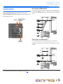
Connecting a TV monitor
This unit is equipped with the following three types of output jack for connection to a TV.
HDMI OUT, COMPONENT VIDEO or VIDEO. Select the proper connection according to the input
signal format supported by your TV.
When connecting to an HDMI compatible TV
Video signal such as component video and video received by this unit is converted to HDMI and output
to the TV. Just select HDMI input on the TV to view video from any external source connected to this
unit. J1
When connecting to a non-HDMI compatible TV
Connect to the TV using the same type of connection that you used to connect to the external
component, and change the inputs on your TV to match that of the external component you are using
for playback.
HDMI
OUT
ARC
MONITOR OUT
COMPONENT
VIDEO
VIDEO
P
R
P
B
Y
CO
MP
O
NEN
T
VIDE
O
P
R
P
B
Y
(BD
/
DVD)
HDMI
2
HDMI
1
HDM
V
IDE
O
DOCK
A
NTENN
A
FM
75
ǡ
G
N
D
AM
HDMI OUT jack
COMPONENT VIDEO jacks
(MONITOR OUT)
VIDEO jack
(MONITOR OUT)
HDMI
COMPONENT
VIDEO
HDMI
VIDEO
S VIDEO
Input Output
HDMI input
Through
Converted
TV
COMPONENT
VIDEO
HDMI
VIDEO
COMPONENT
VIDEO
HDMI
VIDEO
S VIDEO
Input Output
Video input
Through
Component
video input
TV
J
1 : You can change the resolution and aspect ratio used when converting to HDMI to suit your requirements (☞p. 55).

En 16
CONNECTIONS
Connecting external components
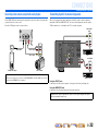
■
Connecting an HDMI video monitor
Connect the HDMI cable to the HDMI OUT jack.
■
Connecting a component video monitor
Connect the component video cable to the COMPONENT VIDEO (MONITOR OUT) jacks.
■
Connecting a video monitor
Connect the video pin cable to the VIDEO (MONITOR OUT) jack.
• Use a 19-pin HDMI cable with the HDMI logo.
• We recommend using a cable less than 5.0 m long to prevent signal quality degradation.
HDMI
OUT
ARC
CO
MP
O
NENT
VIDE
O
P
R
P
B
Y
O
PTI
C
A
L
O
PTI
C
A
L
(
TV
)
AV 1
AV 2
AV 3
AV 4
AV 5
AV 6
AUDI O 1
AUDI O 2
CO
AXIAL
CO
AXIA
L
(C
D
)
(
BD
/
DVD
)
HDMI 2
HDMI 1
AV
OU
T
V
IDE
O
D
OC
K
ANTENNA
FM
75
ǡ
G
ND
AM
M
O
NIT
O
R
O
UT
C
OMPONENT
V
IDE
O
V
IDE
O
P
R
P
B
Y
HDMI
HDMI
HDMI
HDMI input
TV
J1
COMPONENT
VIDEO
P
R
P
B
Y
CO
MP
O
NENT
VIDE
O
P
R
P
B
Y
O
PTI
C
A
L
O
PTI
C
AL
(
TV
)
AV
1
AV
2
AV
3
AV
4
AV
5
AV
6
AUDI O 1
AUDI O 2
CO
AXIAL
CO
AXIA
L
(
CD
)
(
BD/DVD
)
HDMI 2
HDMI 1
HDMI
OU
T
AV
O
UT
VIDE
O
DOCK
AR
C
ANTENNA
F
M
75
ǡ
G
N
D
A
M
R
OU
T
V
IDE
O
COMPONENT
VIDEO
Y
P
R
P
B
Y
P
R
P
B
Component video input
TV
J1
VIDEO
CO
MP
O
NENT
VIDE
O
P
R
P
B
Y
O
PTI
C
A
L
O
PTI
C
AL
(
TV)
AV 1
AV 2
AV 3
AV 4
AV 5
AV 6
AUDI O 1
AUDI O 2
CO
AXIAL
CO
AXIA
L
(
C
D
)
(
BD
/
DVD
)
HDMI 2
HDMI 1
HDMI
O
UT
A
V
OU
T
VIDE
O
DOCK
A
R
C
ANTENNA
FM
75
ǡ
GN
D
AM
MO
NIT
O
CO
MP
O
NENT
VIDE
O
P
R
P
B
Y
VIDEO
V
V
Video input
TV
J
1 : When connecting to a TV that supports HDMI input, the video signal for the COMPONENT VIDEO/VIDEO jacks is
converted and output from HDMI OUT jack. When connecting to a TV via the HDMI jack, you do not need to use these
jacks.

En 17
CONNECTIONS
Connecting external components
■ Listening to TV audio
To transmit sound from the TV to this unit, connect as followings according to the TV:
When using a TV that supports the Audio Return Channel function and HDMI
Control function
When your TV supports both HDMI Control (Ex. Panasonic VIERA Link) and Audio Return
Channel functions, audio/video output from the unit to the TV and audio output from the TV to the
unit are possible using a single HDMI cable.
The input source is switched automatically to match operations carried out on the TV, and that
makes TV sound control easier to use.
For the connections and settings, refer to “Single HDMI cable input to TV audio with Audio Return
Channel function” (☞
p. 70).
When using a TV that supports the HDMI Control functions
When using a TV that supports HDMI Control functions (Ex. Panasonic VIERA Link), if HDMI
Control functions are enabled on the unit, then input source can be switched automatically to match
operations carried out on the TV.
For the connections and settings, refer to “Switching the input source on this unit automatically
when listening to TV audio” (☞
p. 69).
When using other TVs
To transmit sound from the TV to this unit, connect its AV1-6 or AUDIO1-2 jacks to the TV’s audio
output jacks.
Depending on the connection on TV, connect the TV’s audio output to the AV1-6 or AUDIO1-2.
Select the input source connected via TV’s audio output jack to enjoy the TV sound.
If the TV supports optical digital audio output, we recommend that you connect the TV audio output
to the receiver’s AV4 jack.
Connecting to AV4 allows you to switch the input source to AV4 with just a single key operation
using the SCENE function (☞
p. 30).
You can control your TV using the receiver’s remote control by entering the TV’s remote control
code (☞p. 63).
TV audio output Connection
Optical digital audio output Connect to the OPTICAL jack of the AV1 or AV4 with a digital audio pin
cable.
Coaxial digital audio output Connect to the COAXIAL jack of the AV2 or AV3 with a fiber-optic cable.
Analog stereo output Connect to one of the AV5, AV6, AUDIO1, AUDIO2, or V-AUX with a
stereo pin cable.
OPTICAL OPTICAL
(TV)
AV 1
AV 2
AV 3
AV 4
AV 5
AV 6
A
UDIO
1
A
UD
IO
2
COAXIAL COAXIAL
(CD)
C
OMPONENT
V
IDE
O
P
R
P
B
Y
(
BD
/
DVD
)
HDMI
2
HDMI
1
HDMI
O
U
T
A
V
O
UT
V
IDE
O
D
OC
K
ARC
ANTENNA
FM
75
ǡ
G
ND
AM
M
O
NIT
O
R
OU
T
COMPONENT
V
IDE
O
V
IDE
O
P
R
P
B
Y
OPTICAL
O
O
Audio output
(Optical)
TV
Available input jacks

En 18
CONNECTIONS
Connecting external components
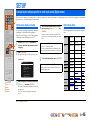
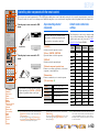
Connecting BD/DVD players and other devices
This unit has the following input jacks. Connect them to the appropriate output jacks on
the playback devices such as BD/DVD players.
■
Connecting BD/DVD players and other devices with
HDMI
Connect the device with an HDMI cable to one of the HDMI1-4 jacks.
Select the HDMI input (HDMI1-4) that the playback device is connected to for
playback.
OPTION
HDMI
1234
ENTER
R
E
C
EIVER
SC
EN
E
S
ETU
P
RETURN
V
O
LUM
E
E
NHANCER
SU
R. DE
CO
D
E
S
TRAI
G
H
T
D
IRE
CT
AV
AUDIO
T
RAN
S
MIT
SLEEP
1
2
3
4
1
2
5
6
V-A
U
X
TU
NE
R
FM
I
NF
O
M
EM
O
R
Y
AM
PRESE
T
T
UNIN
G
MO
VI
E
M
US
I
C
S
TERE
O
BD
D
VD
TV
C
D
R
ADI
O
MU
TE
7
8
5
6
9
0
10
1
2
3
4
R
E
C
EN
T
TV
T
V V
OL
T
V
C
H
T
O
P
MENU
PO
P-
UP
MENU
D
I
S
PLA
Y
SOURCE
CO
DE
S
ET
I
NP
U
T
M
U
T
E
DOCK
[
A
]
[
B
]
q
j
d
dInput selector
jCursor C / D / E
jENTER
qOPTION
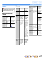
Input jack Video input Audio input
HDMI1 HDMI HDMI
HDMI2 HDMI HDMI
HDMI3 HDMI HDMI
HDMI4 HDMI HDMI
AV1 Component video Optical digital
AV2 Component video Coaxial digital
AV3 Video Coaxial digital
AV4 Video Optical digital
AV5 Video Analog (Stereo)
AV6 Video Analog (Stereo)
AUDIO1 — Analog (Stereo)
AUDIO2 — Analog (Stereo)
VIDEO AUX Video Analog (Stereo)
CO
MP
O
NENT
VIDE
O
P
R
P
B
Y
OPTICA
L
OPTICAL
(
TV
)
AV 1
AV 2
AV 3
AV 4
AV 5
AV 6
AUDI O 1
AUDIO 2
C
OAXIA
L
COAXIA
L
(C
D
)
FRON
T
HDMI
O
UT
AV
OUT
A
UDIO
OU
T
V
IDE
O
DOC
K
AR
C
ANTENNA
FM
75
ǡ
G
N
D
A
M
M
O
NIT
O
R
O
UT
CO
MP
O
NEN
T
VIDE
O
VIDE
O
P
R
P
B
Y
HDMI
HDMI
HDMI
HDMI output
BD/DVD player
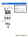
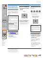
■ Receiving video signals from the HDMI jack and audio signals
from a jack other than HDMI
This unit can use the AV1-6 or AUDIO1-2 input jacks to receive audio signals from
other input jacks.
For example, if an playback device cannot produce audio signals from an HDMI
jack, use the following method to change the audio input.
1
Use the dInput selector to select the desired HDMI input source.
2
Press qOPTION to display the Option menu. J1
3
Press jCursor C repeatedly to select “Audio In,” and then press
jENTER.
4
Press jCursor D / E to select the audio input source.
When the video input source from this unit is selected on TV, the menu items are
displayed on the TV screen (On-Screen Display).
5
Once you have completed the setup, press qOPTION to close the
Option menu.
J
1 : When operating the Option menu, information is displayed both on the TV screen (On-Screen Display)
and on the front panel. Refer to the “Configuring the settings specific for each input source (Option
menu)” (☞
p. 45) for details on the Option menu.
OPTICAL
(BD/DVD)
HDMI 1
C
OMPONEN
T
V
IDE
O
P
R
P
B
Y
OPTICAL
(TV)
A
V
2
A
V
3
A
V
4
A
V
5
A
V
6
AUDIO 1
AUDIO 2
C
OAXIA
L
C
OAXIA
L
(
CD)
HDMI
2
H
DMI
OUT
AV
OU
T
V
IDE
O
D
OC
K
A
R
C
ANTENNA
F
M
75
ǡ
G
N
D
AM
M
O
NIT
O
R
OUT
COMPONENT
VIDE
O
VIDE
O
P
R
P
B
Y
HDMI
OPTICAL
HDMI
HDMI
O
O
HDMI/Audio (Optical)
output
BD/DVD player
HDMI1OPTION
AudioIn
;;;;;;
AV1
If you have selected AV1 input audio (optical digital)

En 19
CONNECTIONS
Connecting external components
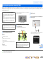
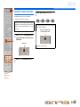
■
Connecting BD/DVD players and other devices with component
cables
Connect the device with a component video cable to one of the AV1-2 input jacks.
Using optical digital audio output sources
Select the AV1 input that the playback device is connected to for playback.
Using coaxial digital audio output sources
Select the AV2 input that the playback device is connected to for playback.
COMPONENT
VIDEO
P
R
P
B
Y
OPTICAL
O
PTICA
L
(
TV
)
AV 2
AV 3
AV 4
AV 5
AV 6
AUDI O 1
AUDI O 2
COAXIAL
C
OAXIA
L
(C
D
)
(
BD
/
DVD
)
HDMI 2
HDMI 1
HDM
I
O
U
T
AV
OU
T
V
IDE
O
D
OC
K
AR
C
ANTENNA
FM
75
ǡ
G
ND
AM
M
O
NIT
O
R
O
UT
C
OMPONENT
V
IDE
O
V
IDE
O
P
R
P
B
Y
COMPONENT
Y
P
R
P
B
Y
P
R
P
B
O
OPTICAL
O
Component video / Audio (Optical)
output
BD/DVD player
AV 2
COAXIAL
CO
MP
O
NENT
VIDEO
P
R
P
B
Y
O
PTICA
L
OPTICAL
(
TV
)
AV 1
AV 3
AV 4
AV 5
AV 6
AUDI O 1
AUDI O 2
C
OAXIAL
(C
D
)
(
BD
/
DVD)
HDMI 2
HDMI 1
HDM
I
O
U
T
AV
OUT
V
IDE
O
D
OC
K
AR
C
ANTENNA
FM
75
ǡ
G
N
D
AM
MO
NIT
O
R
O
UT
C
OMPONENT
VIDE
O
V
IDE
O
P
R
P
B
Y
COMPONENT
VIDEO
COAXIAL
Y
P
R
C
P
B
Y
P
R
P
B
C
Component video / Audio (Coaxial)
output
BD/DVD player
■ Component connections to analog audio output devices
You can use the video input from the AV1-2 jacks in combination with the audio input from other
AV inputs or AUDIO1-2.
When connecting these devices, select the AV input jacks or the AUDIO1-2 jacks as the audio input
for AV1 or AV2. Refer to “Receiving video signals from the HDMI jack and audio signals from a
jack other than HDMI” (☞
p. 18) for detailed setup guidance.
Select the AV input source (AV1-2) that is connected by component video cable to the playback
device for playback. When the video input source from this unit is selected on TV, the menu items
are displayed on the TV display (On-Screen Display).
COMPONENT
VIDEO
P
R
P
B
Y
AUDIO 1
O
PTI
C
A
L
O
PTI
C
AL
(
TV
)
A
V
1
A
V
2
A
V
3
A
V
4
A
V
5
A
V
6
AUDIO 2
CO
AXIAL
CO
AXIA
L
(C
D
)
(
BD
/
DVD)
HDMI 2HDMI 1
HDMI
O
UT
AV
O
U
T
VIDE
O
D
OC
K
AR
C
ANTENNA
FM
75
ǡ
G
ND
AM
M
O
NIT
O
R
OU
T
CO
MP
O
NEN
T
V
IDE
O
V
IDE
O
P
R
P
B
Y
AUDIO
COMPONENT
VIDEO
R
L
R
L
Y
P
R
P
B
Y
P
R
P
B
Component video / Audio
output
Game console
AV1OPTION
AudioIn
;;;
AUDIO1
If you have selected AUDIO1 input audio (Analog stereo)

En 20
CONNECTIONS
Connecting external components
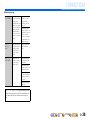
■
Connecting BD/DVD players and other devices with S-video
cables (U.K. and Europe models only)
Connect the S-video cable to the AV5 input jack. Connect the output audio to the AV5 analog audio
jack.
Select the AV5 input source for connected video output that the playback device is connected to for
playback. Video from the S VIDEO jack is output through the HDMI OUT jack only.
■
Connecting BD/DVD players and other devices with video cables
Connect the playback device with a video pin cable to one of the AV3-6 input jacks.
Using optical digital audio output sources
Select the AV4 input that the playback device is connected to for playback.
Using coaxial digital audio output sources
Select the AV3 input that the playback device is connected to for playback.
Using analog stereo audio output sources
Select the AV5 or AV6 input that the playback device is connected to for playback.
AV 5
CO
MP
O
NEN
T
V
IDEO
P
R
P
B
Y
O
PTICA
L
OPTICA
L
(
TV
)
AV 1
AV 2
AV 3
AV 4
AV 6
AUDI O 1
AUDI O 2
C
OAXIA
L
COAXIAL
(C
D
)
(BD
/
DVD)
HDMI 2
HDMI 1
H
DMI
O
UT
AV
OUT
VIDE
O
DOCK
A
R
C
ANTENNA
FM
75
ǡ
G
N
D
AM
MO
NIT
O
R
O
UT
COMPONENT
VIDE
O
VIDE
O
P
R
P
B
Y
AUDIO
VIDEO
R
L
R
L
S
S
S
S-video / Audio output
BD/DVD player
OPTICAL
CO
MP
O
NEN
T
V
IDEO
P
R
P
B
Y
O
PTICA
L
AV 1
AV 2
AV 3
AV 5
AV 6
AUDI O 1
AUDI O 2
C
OAXIA
L
COAXIAL
(C
D
)
(BD
/
DVD)
HDMI 2
HDMI 1
H
DMI
O
UT
AV
OUT
VIDE
O
DOCK
AR
C
ANTENNA
FM
75
ǡ
G
N
D
AM
MO
NIT
O
R
O
UT
COMPONENT
VIDE
O
VIDE
O
P
R
P
B
Y
VIDEO
OPTICAL
V
V
O
O
Video / Audio (Optical)
output
BD/DVD player
COAXIAL
(CD)
VIDEO
CO
MP
O
NEN
T
V
IDEO
P
R
P
B
Y
O
PTICA
L
OPTICA
L
(
TV
)
AV 1
AV 2
AV 4
AV 5
AV 6
AUDI O 1
AUDI O 2
C
OAXIA
L
(BD
/
DVD)
HDMI 2
HDMI 1
H
DMI
O
UT
AV
OUT
DOCK
A
R
C
ANTENNA
FM
75
ǡ
G
N
D
AM
MO
NIT
O
R
O
UT
COMPONENT
VIDE
O
VIDE
O
P
R
P
B
Y
VIDEO
COAXIAL
V
V
C
C
Video / Audio (Coaxial)
output
BD/DVD player
CO
MP
O
NEN
T
V
IDEO
P
R
P
B
Y
O
PTICA
L
OPTICA
L
(
TV
)
AV 1
AV 2
AV 3
AV 4
AUDI O 1
AUDI O 2
C
OAXIA
L
COAXIAL
(C
D
)
(BD
/
DVD)
HDMI 2
HDMI 1
H
DMI
O
UT
AV
OUT
VIDE
O
DOCK
AR
C
ANTENNA
FM
75
ǡ
G
N
D
AM
MO
NIT
O
R
O
UT
COMPONENT
VIDE
O
VIDE
O
P
R
P
B
Y
AUDIO
VIDEO
R
L
R
L
V
V
Video / Audio
output
BD/DVD player
Sayfa yükleniyor ...
Sayfa yükleniyor ...
Sayfa yükleniyor ...
Sayfa yükleniyor ...
Sayfa yükleniyor ...
Sayfa yükleniyor ...
Sayfa yükleniyor ...
Sayfa yükleniyor ...
Sayfa yükleniyor ...
Sayfa yükleniyor ...
Sayfa yükleniyor ...
Sayfa yükleniyor ...
Sayfa yükleniyor ...
Sayfa yükleniyor ...
Sayfa yükleniyor ...
Sayfa yükleniyor ...
Sayfa yükleniyor ...
Sayfa yükleniyor ...
Sayfa yükleniyor ...
Sayfa yükleniyor ...
Sayfa yükleniyor ...
Sayfa yükleniyor ...
Sayfa yükleniyor ...
Sayfa yükleniyor ...
Sayfa yükleniyor ...
Sayfa yükleniyor ...
Sayfa yükleniyor ...
Sayfa yükleniyor ...
Sayfa yükleniyor ...
Sayfa yükleniyor ...
Sayfa yükleniyor ...
Sayfa yükleniyor ...
Sayfa yükleniyor ...
Sayfa yükleniyor ...
Sayfa yükleniyor ...
Sayfa yükleniyor ...
Sayfa yükleniyor ...
Sayfa yükleniyor ...
Sayfa yükleniyor ...
Sayfa yükleniyor ...
Sayfa yükleniyor ...
Sayfa yükleniyor ...
Sayfa yükleniyor ...
Sayfa yükleniyor ...
Sayfa yükleniyor ...
Sayfa yükleniyor ...
Sayfa yükleniyor ...
Sayfa yükleniyor ...
Sayfa yükleniyor ...
Sayfa yükleniyor ...
Sayfa yükleniyor ...
Sayfa yükleniyor ...
Sayfa yükleniyor ...
Sayfa yükleniyor ...
Sayfa yükleniyor ...
Sayfa yükleniyor ...
Sayfa yükleniyor ...
Sayfa yükleniyor ...
Sayfa yükleniyor ...
Sayfa yükleniyor ...
Sayfa yükleniyor ...
Sayfa yükleniyor ...
Sayfa yükleniyor ...
Sayfa yükleniyor ...
-
 1
1
-
 2
2
-
 3
3
-
 4
4
-
 5
5
-
 6
6
-
 7
7
-
 8
8
-
 9
9
-
 10
10
-
 11
11
-
 12
12
-
 13
13
-
 14
14
-
 15
15
-
 16
16
-
 17
17
-
 18
18
-
 19
19
-
 20
20
-
 21
21
-
 22
22
-
 23
23
-
 24
24
-
 25
25
-
 26
26
-
 27
27
-
 28
28
-
 29
29
-
 30
30
-
 31
31
-
 32
32
-
 33
33
-
 34
34
-
 35
35
-
 36
36
-
 37
37
-
 38
38
-
 39
39
-
 40
40
-
 41
41
-
 42
42
-
 43
43
-
 44
44
-
 45
45
-
 46
46
-
 47
47
-
 48
48
-
 49
49
-
 50
50
-
 51
51
-
 52
52
-
 53
53
-
 54
54
-
 55
55
-
 56
56
-
 57
57
-
 58
58
-
 59
59
-
 60
60
-
 61
61
-
 62
62
-
 63
63
-
 64
64
-
 65
65
-
 66
66
-
 67
67
-
 68
68
-
 69
69
-
 70
70
-
 71
71
-
 72
72
-
 73
73
-
 74
74
-
 75
75
-
 76
76
-
 77
77
-
 78
78
-
 79
79
-
 80
80
-
 81
81
-
 82
82
-
 83
83
-
 84
84


Diğer dillerde
- español: Yamaha HTR-5063 El manual del propietario
- português: Yamaha HTR-5063 Manual do proprietário
- English: Yamaha HTR-5063 Owner's manual
- suomi: Yamaha HTR-5063 Omistajan opas
- română: Yamaha HTR-5063 Manualul proprietarului