Acson E Series Yükleme Rehberi
- Kategori
- Split sistem klimalar
- Tip
- Yükleme Rehberi

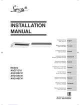
CEILING CASSETTE
SPLIT TYPE AIR CONDITIONER
(E Series)
CEILING CASSETTE
INSTALLATION MANUAL
IM-CKE-0209(0)-ACSON
Part No.: R08019032819


1-1
English
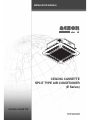
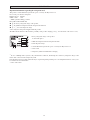
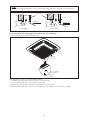
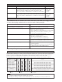
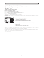
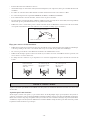
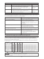
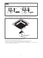
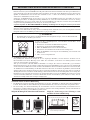
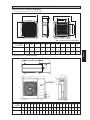
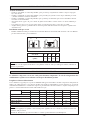
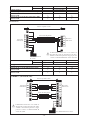
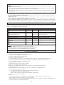
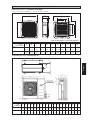
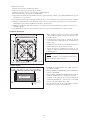
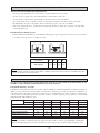
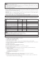
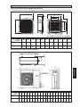
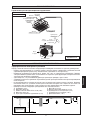
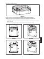
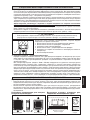
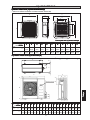
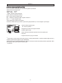
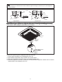
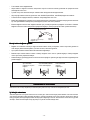
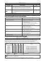
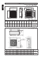
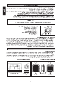
OUTLINE AND DIMENSIONS
AB CDEF GHIJK
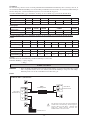
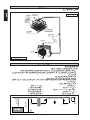
(5)CK20/25/28E(R) 820 820 340 300 40 990 990 627 627 607 430
(32.3) (32.3) (13.4) (11.8) (1.6) (39.0) (39.0) (24.7) (24.7) (23.9) (16.9)
(5)CK40/50E(R) 820 820 375 335 40 990 990 627 627 607 430
(32.3) (32.3) (14.8) (13.2) (1.6) (39.0) (39.0) (24.7) (24.7) (23.9) (16.9)
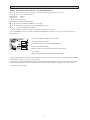
Indoor Unit (5)CK20/25/28/40/50E(R) Series
• (With Wireless Remote Control & With Wired Remote Control)
All dimensions are in mm/(in)
A
B
C
D
E
F
H
K
J
I
G
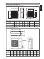
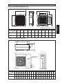
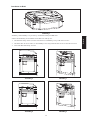
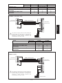
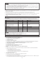
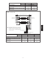
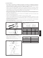
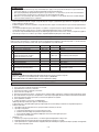
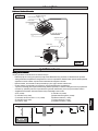
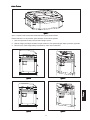
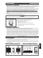
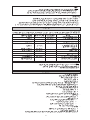
Outdoor Unit (5)SL20/25/28C(R) Series
All dimensions are in mm/(in)
ABCDEFGH I JKLMNOPQRST
(5)SL20C(R) 855 628 328 508 181 44 93 149 101 113 603 126 164 15 49 3 23 73 75 362
(33.7) (24.7) (12.9) (20.0) (7.1) (1.7) (3.7) (5.9) (4.0) (4.4) (23.7) (5.0) (6.5) (0.6) (1.9) (0.1) (0.9) (2.9) (3.0) (14.3)
(5)SL25/28C(R) 855 730 328 513 182 44 93 149 101 113 603 126 164 15 47 3 23 73 75 362
(33.7) (28.7) (12.9) (20.2) (7.2) (1.7) (3.7) (5.9) (4.0) (4.4) (23.7) (5.0) (6.5) (0.6) (1.9) (0.1) (0.9) (2.9) (3.0) (14.3)
N
L
KL
TN
M
A
D
O
P
BQ
RS
C
HG
FE
IJ
FOR 25/28CR ONLY
Model
Dimension
Model
Dimension

1-2
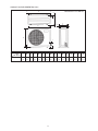
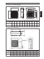
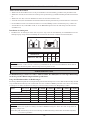
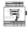
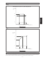
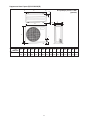
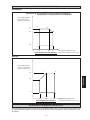
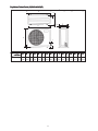
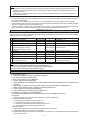
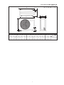
Outdoor Unit (5)SL35/40/50C(R) Series
A
B
G
D
E
H
I
J
L
M
O
C
F
All dimensions are in mm/(in)
K
N
ABCDEFGHI JKLMNOP
(5)SL35/40/50C(R)
141.5 746.5 141.5 20 448 20 1030 850 25 50 85 400 40 320 40 75
(5.6) (29.4) (5.6) (0.8) (17.6) (0.8) (40.6) (33.5) (1.0) (2.0) (3.3) (15.7) (1.6) (12.6) (1.6) (2.9)
P
Model
Dimension

1-3
English
! CAUTION
Please take note of the following important points when
installing.
• Do not install the unit where leakage of flammable
gas may occur.
If gas leaks and accumulates around the unit, it
may cause fire ignition.
• Ensure that drainage piping is connected properly.
If the drainage piping is not connected properly, it
may cause water leakage which will dampen the
furniture.
• Do not overcharge the unit.
This unit is factory pre-charged.
Overcharge will cause over-current or damage to
the compressor.
• Ensure that the unit’s panel is closed after service
or installation.
Unsecured panels will cause the unit to operate
noisily.
• Sharp edges and coil surfaces are potential locations
which may cause injury hazards.
Avoid from being in contact with these places.
• Before turning off the power supply, set the remote
controller’s ON/OFF switch to the “OFF” position
to prevent the nuisance tripping of the unit. If this is
not done, the unit’s fans will start turning automatically
when power resumes, posing a hazard to service
personnel or the user.
• Do not operate any heating apparatus too close to
the air conditioner unit. This may cause the plastic
panel to melt or deform as a result of the excessive heat.
• Ensure the color of wires of the outdoor unit and
the terminal markings are same to the indoors
respectively.
• IMPORTANT : DO NOT INSTALL OR USE THE
AIR CONDITIONER UNIT IN A LAUNDRY
ROOM.
• Don’t use joined and twisted wires for incoming
power supply.
! WARNING
• Installation and maintenance should be performed by
qualified persons who are familiar with local code and
regulation, and experienced with this type of appliance.
• All field wiring must be installed in accordance with
the national wiring regulation.
• Ensure that the rated voltage of the unit corresponds to
that of the name plate before commencing wiring work
according to the wiring diagram.
• The unit must be GROUNDED to prevent possible
hazard due to insulation failure.
• All electrical wiring must not touch the refrigerant
piping, or any moving parts of the fan motors.
• Confirm that the unit has been switched OFF before
installing or servicing the unit.
• Disconnect from the main power supply before servicing
the air conditioner unit.
• DO NOT pull out the power cord when the power is
ON. This may cause serious electrical shocks which
may result in fire hazards.
• Keep the indoor and outdoor units, power cable and
transmission wiring, at least 1m from TVs and radios,
to prevent distorted pictures and static. {Depending on
the type and source of the electrical waves, static may
be heard even when more than 1m away}.
This manual provides the procedures of installation to ensure a safe and good standard of operation for the air
conditioner unit.
Special adjustment may be necessary to suit local requirements.
Before using your air conditioner, please read this instruction manual carefully and keep it for future reference.
INSTALLATION MANUAL
SAFETY PRECAUTIONS
Disposal requirements
Your air conditioning product is marked with this symbol. This means that electrical and electronic products shall
not be mixed with unsorted household waste.
Do not try to dismantle the system yourself: the dismantling of the air conditioning system, treatment of the refrigerant,
of oil and of other parts must be done by a qualified installer in accordance with relevant local and national legislation.
Air conditioners must be treated at a specialized treatment facility for re-use, recycling and recovery. By ensuring
this product is disposed of correctly, you will help to prevent potential negative consequences for the environment
and human health. Please contact the installer or local authority for more information.
Batteries must be removed from the remote controller and disposed of separately in accordance with relevant local
and national legislation.
NOTICE

1-4
Important information regarding the refrigerant used
This product contains fluorinated greenhouse gases covered by the Kyoto Protocol.
Do not vent gases into the atmosphere.
Refrigerant type: R410A
GWP
(1)
value: 1975
(1)
GWP = global warming potential
Please fill in with indelible ink,
1 the factory refrigerant charge of the product,
2 the additional refrigerant amount charged in the field and
1 + 2 the total refrigerant charge
on the refrigerant charge label supplied with the product.
The filled out label must be adhered in the proximity of the product charging port (e.g. onto the inside of the service cover).
1 factory refrigerant charge of the product:
see unit name plate
(2)
2 additional refrigerant amount charged in the field
3 total refrigerant charge
4 contains fluorinated greenhouse gases covered by the Kyoto Protocol
5 outdoor unit
6 refrigerant cylinder and manifold for charging
(2)
In case of multiple indoor systems, only 1 label must be adhered*, mentioning the total factory refrigerant charge of all
indoor units connected in the refrigerant system.
Periodical inspections for refrigerant leaks may be required depending on European or local legislation. Please contact your
local dealer for more information.
* on the outdoor unit
IMPORTANT

1-5
English
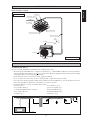
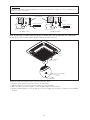
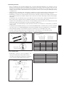
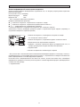
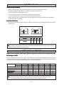
Indoor Unit
Outdoor Unit
Drain Hose
Front Panel
Air Filter
(behind the grille)
Air Discharge Louver
Air Intake Grille
Refrigerant Piping
Air Discharge
Wireless Remote Control
Air Discharge Louver
Remote Control
INSTALLATION DIAGRAM
Air Intake
Air Intake
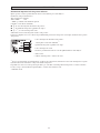
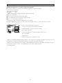
INSTALLATION OF THE INDOOR UNIT
Preliminary Site Survey
Be sure to read this manual before installing the air-conditioner indoor unit.
• Electrical supply and installation is to conform to local authority’s (e.g. National Electrical Board) codes and regulations.
• Voltage supply fluctuation must not exceed
+
10% of rated voltage. Electricity supply lines must be independent of welding
transformers which can cause high supply fluctuation.
• Ensure that the location is convenient for wiring, piping and drainage.
• Do not exert pressure on the resin parts when opening the unit or when moving it after opening.
• Do not move the unit from packaging while moving, until it reaches the installation site. Use safe material or protection
plates when unpacking it or lifting it to avoid damage or scratches to the unit.
• Check the following accessories are include with your unit:
a) Battery (2pcs) f) Screw M4 x 6 (2pcs)
b) Screw M6 x 40 (4pcs) g) Cover lock grille (2pcs)
c) Washer, flat OD19 x ID17 x t1.0 (4pcs) h) Operation Manual (1pc)
d) Screw M4 x 20 (2pcs) i) Installation Manual (1pc)
e) Handset (1pc) j) Drain hose (1pc)
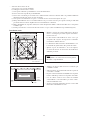
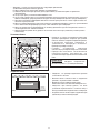
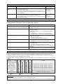
Min. 0.5m Min. 0.5m Min. 0.5m
Max. 0.3m
Max. 3.0m
Min. 1.0m
Floor
Obstacle
Beam

1-6
• Ensure a location where:
a) Drainage can be done easily.
b) Convenient for wiring and piping.
c) Which have enough space for installation and service work.
d) Where no risk of flammable gas leakage.
e) When free from any obstacles in path of cool air discharge and warm air return and must allow spreading of air throughout
the room (near the center of the room).
f) Must be provided clearance for indoor unit from the wall and obstacles as shown in figure below.
g) The installation place must be strong enough to support a load 4 times the indoor unit weight to avoid amplifying noise
and vibration.
h) The installation place (hanging ceiling surface) must be assuring levelness and the height in the ceiling is 350mm or
more.
i) The indoor unit must be away from heat and steam sources (avoid installing it near an entrance).
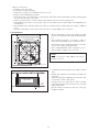
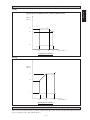
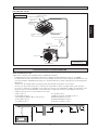
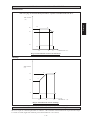
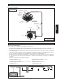
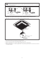
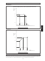
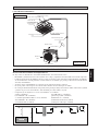
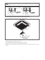
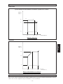
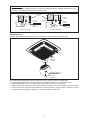
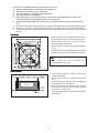
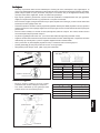
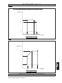
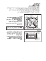
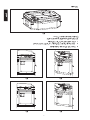
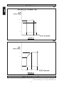
Unit Installation
• Measure and mark the position for the hanging rod. Drill
the hole for the angle nut on the ceiling and fix the hanging
rod.
• The installation template is extended according to
temperature and humidity. Check on dimensions in use.
• The dimensions of the installation template are the same
as those of the ceiling opening dimensions.
• Before ceiling laminating work is completed, be sure to
fit the installation template to the indoor unit.
NOTE
Be sure to discuss the ceiling drilling work with the
installers concerned.
770.0mm (Hanging Rod)
622.0mm (Hanging Rod)
Piping Direction
880.0~990.0mm (Ceiling Opening Site = 890mm)
990.0mm
880.0~990.0mm (Ceiling Opening Site)
990.0mm
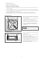
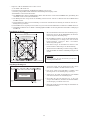
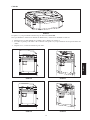
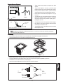
• Confirm the pitch of the hanging rod is 770mm × 622mm
sharp.
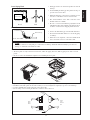
• Hold the unit and hang it on the hanging rod with the nut
and washer.
• Adjust the unit height to 30.0mm between the indoor unit
bottom surface and the ceiling surface.
• Confirm with a level gauge that the unit is installed
horizontally and tighten the nut and bolt to prevent unit
falling and vibration.
• Open the ceiling board along the outer edge of the paper
installation template.
Unit Hanging
Indoor Unit
30.0mm
Ceiling
Board

1-7
English
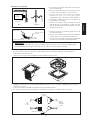
Main Drain Pipe
Feed Water
Flexible Drain Hose
Drain Test
NOTE
This Indoor Unit uses a drain pump for condensed water drainage. Install the unit horizontally to prevent water
leakage or condensation around the air outlet.
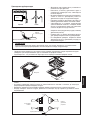
Indoor Unit
Pipe Clamp
Good
Bad
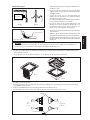
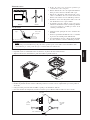
Drain Piping Work
• Drain pipe must be in downward gradient for smooth
drainage.
• Avoid installing the drain pipe in up and down slope to
prevent reversed water flow.
• During the drain pipe connection, be careful not to exert
extra force on the drain connector at indoor unit.
• The outside diameter of the drain connection at the
flexible drain hose is 20mm.
• Be sure to execute heat insulation (polyethylene foam
with thickness more than 8.0mm) on the drain piping to
avoid the condensed water dripping inside the room.
• Connect the main drain pipe to the flexible drain hose.
• Feed water from flexible drain hose to check the piping
for leakage.
• When the test is completed, connect the flexible drain
hose to the drain connector on the indoor unit.
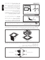
• The front panel can only be fitted in one direction, follow the piping direction. (Follow piping arrow sticker on front
panel)
• Be sure to remove the installation template before installing the front panel.
Panel Installation
Open
Screw
• Open the air intake grille by pulling back the catchers and removing it together with filter from panel.
• Install the front frame panel onto the indoor unit by 4 screws and tighten it completely to prevent cool air leakage.
• Connect the LED wire and air swing wire to the indoor unit.
• The air swing connector must put inside the control box after connected.
From
Unit
Control
Box
From
Front
Panel
LED Wire
Air Swing Wire

1-8
Cover Lock Grille (The moving part protection for user direct touching)
Cover lock grill must be installed as the figure below.
If the unit need to be service, steps below shall be followed:
1. Confirm that the unit had been switched off before servicing the unit.
2. Use screwdriver to unlock the screw on the cover lock grille.
3. Remove the cover lock grille and open the intake grille for the service purpose.
4. Install the intake grille and screw the cover lock grille after service and make sure the unit is proper install.
Frame
Intake Grille
Cover Lock Grille
(2pcs)
Screw M4 x 6
(2pcs)
NOTE
Install the front frame panel firmly to prevent cool air leakage which will cause condensation and water dripping.
Indoor Unit
Cool
Air
Ceiling Board
Panel
Air Leak
Good Installation
Bad Installation
Cool
Air
Air Leak
Ceiling Board
Panel

1-9
English
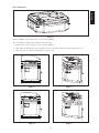
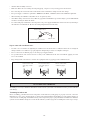
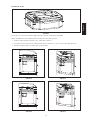
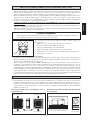
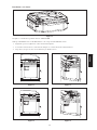
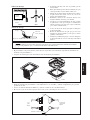
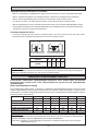
Wires Installation
Figure 1 and Figure 2 shows the location of cover wire in CKE unit.
Steps to install power supply wires and wires from outdoor unit.
1. Remove wire cover by removing 2 screws as shown in Figure 3.
2. Wires will go through the hole as shown in figure 4 and 5 respectively without crossing the height of the hole.
3. After that, wire cover will be assembled back to close the wire.
Figure 1
Figure 2
Figure 4
Figure 3
Figure 5

1-10
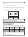
INSTALLATION OF THE OUTDOOR UNIT
Preliminary Site Survey
• A place protected from rain, direct sunlight and well-ventilated wherever practicable.
• A place capable of bearing the weight of the outdoor unit and isolating noise and vibration.
• A place where there are no obstruction of air flow into or out the unit.
• Do not put any object which may become obstacle for the air flow into or out the outdoor unit.
• The location must not be susceptible to high concentration dust, oil, salt or sulfide gas.
• Select the coolest possible place where intake air temperature is not greater than the outside air temperature (maximum
45°C).
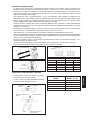
SL series A B C D
Min. distance, mm (in)
300 1000 300 500
(11.8) (39.4) (11.8) (19.7)
Outdoor Unit Installation
• Install the outdoor unit firmly and horizontally. Maintain a space clearance from the obstruction as shown in below for
servicing and air ventilation.
AB
C
D
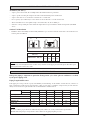
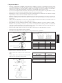
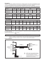
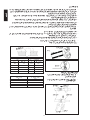
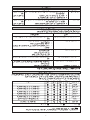
REFRIGERANT PIPING WORK
Refrigerant piping is important in particular. Refrigeration cycle of the split air conditioner is realized
by the perfect piping work.
Piping Length And Elevation
If the piping is too long, both the capacity and reliability of unit will drop. As the number of bends increase, resistance to
flow of refrigerant system increases, thus lowering cooling capacity and as a result the compressor may become defective.
Always choose the shortest path and follow the recommendation as tabulated below.
Model Indoor (5)CK20E(R) (5)CK25E(R) (5)CK28E(R) (5)CK40E(R) (5)CK40E(R) (5)CK50E(R)
Outdoor (5)SL20C(R) (5)SL25C(R) (5)SL28C(R) (5)SL35C(R) (5)SL40C(R) (5)SL50C(R)
Max. length (m) 15m 15m 15m 45m 45m 45m
Max. elevation (m) 8m 8m 8m 25m 25m 25m
Max. no. of bends 10 10 10 10 10 10
Liquid pipe size 1/4" 3/8" 3/8" 3/8" 3/8" 3/8"
Gas pipe size 5/8" 5/8" 5/8" 3/4" 3/4" 3/4"
NOTE
If there is any obstacle higher than 2m, or if there is any obstruction at the upper part of the unit, please allow more space
than figure indicated at the above table.
NOTE
Be sure to add the proper amount of additional refrigerant, failure to do so may result in reduced performance.
Remark: The refrigerant pre-charged in the outdoor unit is for the piping length up to 7.5m.

1-11
English
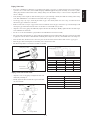
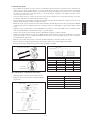
Piping Connection
• Do not use contaminated or damaged copper tubing. If any piping, evaporator or condenser had been exposed or had been
opened for 15 seconds or more, then vacuum and purge with field supplied refrigerant. Generally, do not remove plastic,
rubber plugs and brass nuts from the valves, fittings, tubing and coils until it is ready to connect suction or liquid line into
valves or fittings.
• If any brazing work is required, ensure that nitrogen gas is passed through coil and joints while the brazing work is being
done. This will eliminate soot formation on the inside wall of copper tubings.
• Cut the pipe stages by stages, advancing the blade of pipe cutter slowly. Extra force and a deep cut will cause more
distortion of pipe and therefore extra burr.
• Remove burrs from cut edges of pipes with a remover. Hold the end of the pipe downward to prevent metal chips from
entering the pipe. This will avoid unevenness on the flare face which will cause gas leak.
• Align the center of the piping and sufficiently tighten the flare nut with fingers. Finally, tighten the flare nut with torque
wrench until the wrench clicks.
• Be sure to execute heat insulation. (polyurethane form with thickness more than 15 mm)
• Except the outdoor unit which is pre-charge with refrigerant R22, the indoor unit and the refrigerant connection pipes must
be purged because the air that contain moisture remaining in the refrigerant cycle may cause malfunction to the compressor.
• Insert the flare nuts, mounted on the connection parts of both the indoor unit and outdoor unit onto the copper pipes.
• Flare the pipe with extra length above the flaring tool as shown in the table.
• The flared edge must be even and not cracked or scratched.
Ø Tube, D A (mm)
Inch mm Imperial Rigid
1/4" 6.35 1.3 0.7
3/8" 9.52 1.6 1.0
1/2" 12.70 1.9 1.3
5/8" 15.88 2.2 1.7
3/4" 19.05 2.5 2.0
Cutting Copper Tube
1/4t
Remove Burr
Copper Tube
Swaging Block
Piping Connection To The Units
• Align the center of the piping and tighten the flare nut
sufficiently with fingers.
• Finally, tighten the flare nut with the torque wrench until
the wrench clicks.
Pipe Size mm / (in) Torque Nm / (ft - lb)
6.35 (1/4) 18 (13.3)
9.53 (3/8) 42 (31.0)
12.7 (1/2) 55 (40.6)
15.88 (5/8) 65 (48.0)
19.05 (3/4) 78 (57.6)
Indoor Piping
Flare Nut
Flared Tube
Flare Joint
Spanar
Torque Wrench

1-12
Additional Charge
The refrigerant is pre-charge in the outdoor unit. If the piping length is less than 7.5m, then additional charge after vacuuming
is not necessary. If the piping length is more than 7.5m then use the additional charge value as indicated in the table.
Additional refrigerant charge [g] per additional 1m length as tabulated (for R22 models)
Cooling only
Indoor CK20E CK25E CK28E CK40E CK50E
Outdoor SL20C SL25C SL28C SL35C SL40C (1PH) SL40C (3PH) SL50C
Additional charge [g/m] 38 38 55 56 55 56 55
Example:
CK25E & SL25C with 13m piping length, additional piping length is 5.5m. Thus,
Additional charge = 5.5[m] x 38[g/m]
= 209[g]
Heat Pump Unit
Additional refrigerant charge [g] per additional 1m length as tabulated (for R410A models)
Cooling only
Indoor 5CK20E 5CK25E 5CK28E 5CK40E 5CK50E
Outdoor 5SL20C 5SL25C 5SL28C
5SL35C(1 PH) 5SL35C (3 PH) 5SL40C (1 PH) 5SL40C (3 PH)
5SL50C
Additional charge [g/m] 9 46232727242524
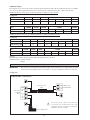
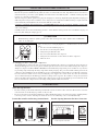
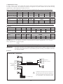
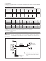
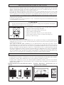
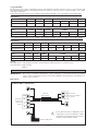
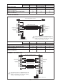
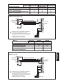
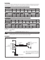
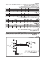
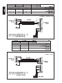
ELECTRICAL WIRING CONNECTION
IMPORTANT: * These values are for information only. They should be checked and selected to comply with local and/or
national codes and regulations. They are also subject to the type of installation and size of conductors.
Cooling Only
COMP
N1
L
N
COMP
N
The electrical power must be provided with
protection devices (circuit breaker or fuse) with
double pole separation system (phase + neutral) with
minimum contact gap of 3.0mm.
(5)CK20/25/28E Vs (5)SL20/25/28C
!
Interconnection
Cable
Indoor Unit
Terminal
Block
Outdoor Unit
Terminal Block
Power Supply Cable
Indoor CK20ER CK25ER CK28ER CK40ER CK50ER
Outdoor SL20CR SL25CR SL28CR SL35CR
SL40CR (1PH) SL40CR (3PH)
SL50CR
Additional charge [g/m] 22 57 58 57 56 56 64
Indoor 5CK20ER 5CK25ER 5CK28ER 5CK40ER 5CK50ER
Outdoor 5SL20CR 5SL25CR 5SL28CR
5SL35CR (1 PH) 5SL35CR (3 PH) 5SL40CR (1 PH) 5SL40CR (3 PH)
5SL50CR
Additional charge [g/m] 16 72 41 43 41 37 37 38
Heat Pump Unit

1-13
English
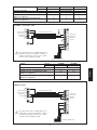
Model Indoor (5)CK20E (5)CK25E (5)CK28E
Outdoor (5)SL20C (5)SL25C (5)SL28C
Voltage range 220-240V/1Ph/50Hz +
!
Recommended fuse* (A) 13 18 25
Power supply cable size* (mm
2
) 2.5 2.5 4.0
Number of conductors 33 3
Interconnection cable size* (mm
2
) 2.5 2.5 2.5
Number of conductors 33 3
R
N
N
L
COMP
S
L
COMP
L
N
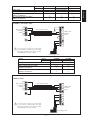
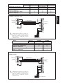
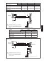
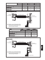
The electrical power must be provided with
protection devices (circuit breaker or fuse) with
double pole separation system (phase + neutral)
with minimum contact gap of 3.0mm.
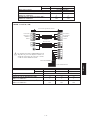
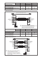
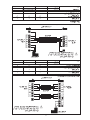
(5)CK40E Vs (5)SL35/40C (1 PH)
Indoor Unit
Terminal
Block
Interconnection Cable
Outdoor Unit
Terminal
Block
!
Power Supply Cable
Model Indoor (5)CK40E (5)CK40E
Outdoor (5)SL35C (5)SL40C
Voltage range 220-240V/1Ph/50Hz +
!
Recommended fuse* (A) 25 30
Power supply cable size* (mm
2
) 4.0 4.0
Number of conductors 33
Interconnection cable size* (mm
2
) 2.5 2.5
Number of conductors 44
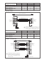
COMP
L
N
COMP
N
L
R
N
S
T
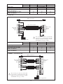
The electrical power must be provided with
protection devices (circuit breaker or fuse) with
double pole separation system (phase + neutral)
with minimum contact gap of 3.0mm.
(5)CK40/50E Vs (5)SL40/50C (3 PH)
5CK40E Vs 5SL35C
Indoor Unit
Terminal
Block
Interconnection Cable
Outdoor Unit
Terminal
Block
!
Power Supply Cable

1-14
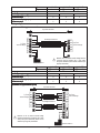
Model Indoor 5CK40E (5)CK40E (5)CK50E
Outdoor 5SL35C (5)SL40R (5)SL50C
Voltage range 380-415V/1Ph/50Hz +
!
Recommended fuse* (A) 10 13 18
Power supply cable size* (mm
2
) 2.5 2.5 2.5
Number of conductors 55 5
Interconnection cable size* (mm
2
) 1.5 1.5 1.5
Number of conductors 44 4
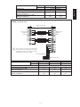
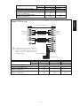
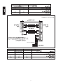
Heat Pump Unit
4WV
OF
N
COMP
4WV
OF
N
COMP
N1
L
The electrical power must be provided with
protection devices (circuit breaker or fuse) with
double pole separation system (phase + neutral)
with minimum contact gap of 3.0mm.
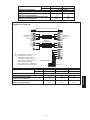
(5)CK20/25/28ER Vs (5)SL20/25/28CR
Indoor Unit
Terminal
Block
Interconnection Cable
Outdoor Unit
Terminal
Block
!
Power Supply Cable
Model Indoor (5)CK20ER (5)CK25ER (5)CK28ER
Outdoor (5)SL20CR (5)SL25CR (5)SL28CR
Voltage range 220-240V/1Ph/50Hz +
!
Recommended fuse* (A) 13 18 18
Power supply cable size* (mm
2
) 2.5 2.5 4.0
Number of conductors 33 3
Interconnection cable size* (mm
2
) 2.5 2.5 2.5
Number of conductors 55 5
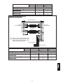
Outdoor Coil Sensor
A
4WV
OF
N
L
COMP
A
4WV
OF
COMP
N
L
N
L
The electrical power must be provided with
protection devices (circuit breaker or fuse) with
double pole separation system (phase + neutral)
with minimum contact gap of 3.0mm.
(5)CK40ER Vs (5)SL35/40CR (1 PH)
Indoor Unit
Terminal
Block
Interconnection Cable
Outdoor Unit
Terminal
Block
!
Power Supply Cable
Outdoor Coil Sensor

1-15
English
Model Indoor (5)CK40ER (5)CK40ER
Outdoor (5)SL35CR (5)SL40CR
Voltage range 220-240V/1Ph/50Hz +
!
Recommended fuse* (A) 25 30
Power supply cable size* (mm
2
) 4.0 4
Number of conductors 33
Interconnection cable size* (mm
2
) 2.5 2.5
Number of conductors 3&4 3&4
A
4WV
OF
COMP
A
R
S
T
4WV
OF
N
COMP
N
L
N
L
The electrical power must be provided with
protection devices (circuit breaker or fuse) with
double pole separation system (phase + neutral)
with minimum contact gap of 3.0mm.
(5)CK40/50ER Vs (5)SL40/50CR (3PH)
5CK40ER Vs 5SL35CR (3PH)
Indoor Unit
Terminal
Block
Interconnection
Cable
Outdoor Unit
Terminal
Block
!
Power Supply Cable
380-415V/3Ph/50Hz
Outdoor Coil Sensor
Model Indoor 5CK40ER (5)CK40ER (5)CK50ER
Outdoor 5SL35CR (5)SL40CR (5)SL50CR
Voltage range 380-415V/3Ph/50Hz +
!
Recommended fuse* (A) 10 13 13
Power supply cable size* (mm
2
) 2.5 2.5 2.5
Number of conductors 55 5
Interconnection cable size* (mm
2
) 1.5 1.5 1.5
Number of conductors 3&4 3&4 3&4

1-16
• All wires must be firmly connected.
• Make sure all the wire not touching the refrigerant piping, compressor or any moving parts of the fan motor.
• The connecting wire between the indoor unit and the outdoor unit must be clamped on the wire clamps.
• The power supply cord must be equivalent to H07RN-F (245 IEC65, 245 IEC66) which is the minimum requirement.
• When attaching the terminal box lid, make sure do not pinch any wires.
• After all the wiring connections are done, fill in any gaps/holes with insulation (procured locally) to prevent small animals
and insects entering the unit from outside.
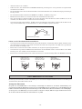
• Use round crimp-style terminal for connecting wires to the power supply terminal block. Connect the wires by matching to
the indication on terminal block. (Refer to the wiring diagram attached on the unit).
Attach insulation sleeve
Round crimp-style terminal
Electric wire
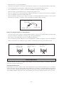
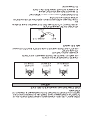
Step to connect the installation wire:
• Used the correct screwdriver for tightening the terminal screws. If the block is too small, the mad of the screw might be
damaged and the screw will not be properly tightened. If tightening too hard, screw might be damaged.
• Do not connect wire at different gauge to the same proper supply terminal.
• Use specified electric wire. Connect the wire securely to the terminal. Lock the wire down without applying excessive
force to the terminal.
• Keep wiring in mat order and not to obstruct other equipment such as popping open the terminal box lid.
Connect wires of the
same gauge to both
side.
Do not connect wires
of the same gauge to
one side.
Do not connect wires
of different gauges.
VACUUMING AND CHARGING
Vacuuming is necessary to eliminate all moisture and air from the system. The series II Outdoor Unit is provided with flare
valve fittings.
Vacuuming for indoor unit
Before vacuuming, perform leak check for refrigeration circuit. After the system piping are properly connected, connect the
flexible hoses to the correct charging nipples as shown in the diagram. Ensure that flexible hose from charging nipples are
connected to the vacuum pump via standard servicing valves and pressure gauges (gauge manifold). Vacuum the air conditioner
system to at least 500 microns Hg. Do not start the unit when the system is engaged in vacuuming. The outdoor is pre-charge.

1-17
English
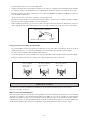
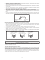
SPECIAL PRECAUTIONS WHEN CHARGING UNIT
1. Charging procedures – Single phase compressors
Evacuate the system to 500 microns Hg. (67Pa). To reduce evacuation time, use short, large diameter hoses and connect to
unrestricted service ports on the system. Quality of vacuum cannot be determined by time – a reliable vacuum gauge must
be used. (etc. electronic vacuum gauge)
Turn the refrigerant cylinder upside down, purge the charging hose and charge liquid through the liquid line charging port
until refrigerant no longer flows or until the correct charge has been weighed in. If additional charge is required start the
system and slowly bleed liquid into the suction side until the system is full.
Copeland recommends charging liquid in a CONTROLLED manner into the suction side until the system is full.
This recommendation does not hold true for reciprocating compressors where liquid charging into the suction side could
cause severe damage.
Carefully monitor the suction and discharge pressures – ensure that the suction pressure does not fall below 25 psig (1.7
bar) at any time during the charging process.
• Manifold Gauge will show cylinder pressure rather than suction pressure if the cylinder valve and Manifold
valve “A” are both open.
! CAUTION
A
There are many ways of charging liquid in a “controlled manner” into the suction
side:-
1. Use valve A on the manifold gauge set
2. Use the valve on the refrigerant cylinder
3. Charge through a Shredder valve
4. Use a hose with a Shredder valve depressor
5. Charge into the suction side at some distance from the compressor
6. All of the above
2. Charging procedures – Three phase compressors
The fundamental procedure is the same as for single phase models but the compressor can run in the wrong direction on
starting. If this happens reverse any two phases and start again. Short term reverse rotation will not damage the compressor.
All Specter compressors (Model: ZR90 to ZR19M) have internal discharge temperature protectors which are very effective
in preventing dangerously high discharge temperatures during charging. The protection module will trip and lock the
compressor out for 30 minutes. It is not normally necessary to wait 30 minutes for the module to reset. When the compressor
has cooled down the module can be reset by breaking the power supply to the control circuit. Very often the serviceman
does not understand why the module tripped and uses a jumper wire to bypass it. He continues to charge the system and
removes the jumper when charging is complete. The compressor may or may not run with the protector back in the circuit
but it is certain that the compressor has been damaged and premature failure is inevitable.
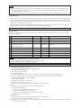
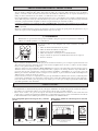
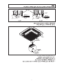
Short Duct Specification
• The indoor unit is provided with air discharge and air intake “knock-out” hole for duct connection. However the connection
of the short duct for air discharge is possible on only one side.
• The use of short duct for air discharge will improve airflow distribution if there is an obstruction (such as a lighting fixture)
or in a long, narrow room or an L-shaped room. It also use for air conditioning of two rooms simultaneously.
ACCESSORY PARTS
Possible Opening Dimension For Duct Connection
Air Discharge Knock Out Hole
Air Intake
Knock Out Hole
Possible Direction For Air Discharge And Air Intake
Air Intake
Air DischargeAir Discharge
Air Discharge Air Discharge
10
50 50 50 50 50 10
207020
90
Ø100
PCD Ø140
115 20 115

1-18
NOTE
• Avoid using the short duct on which the air discharge grille can be completely closed, to prevent evaporator freezing.
• In order to prevent condensation forming, be sure that there is sufficient thermal insulation and no leakage of cool
air when installing the short duct.
• Keep the introduction of fresh air intake within 20% of total air flow. Also provide a chamber and use a booster fan.
Sealing Material
• It is possible to seal one of the four air discharge outlet. (sealing two or more air discharge outlet could cause a malfunction)
• Remove the front panel and insert the sealing material into the air discharge outlet on the indoor unit to seal the air outlet.
• The sealing material is the same length as the longer air discharge outlet. If it is desired to seal the shorter air discharge
outlet, cut the sealing material to shorten it.
• Push the sealing material in about 10 mm beyond the bottom surface of the indoor unit so that it does not touch the air
louver. Be sure not to push the sealing material in any farther than about 10mm.
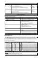
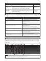
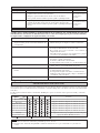
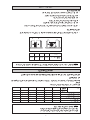
INDICATOR LIGHTS
Remote Control
When there is infrared remote control operating signal, the signal receiver on indoor unit will made a <beep> for signal
acceptance confirmation.
NOTE
CDF LED = Cool/Dry/Fan LED, turns on in these modes
The unit will not detect sensor missing when the compressor is ON
Call your dealer immediately when this error happen
OVERALL CHECKING
• After installation of the unit, ensure that :-
1. The unit has been mounted solidly and rigid in position.
2. Outdoor unit is fully installed
3. Gas leak test is been checked.
4. Unit is fully insulated.
5. The drainage is flow smoothly - pour some water into the main drain pipe from the flexible drain hose.
6. The power supply, voltage correspond to that unit shown on wiring diagram are attached on the unit.
7. Wiring and piping install correctly and firmly.
8. Unit is safely grounded.
9. Wiring size is according to specification.
10. Air inlet and outlet are not blocked.
11. Note down the refrigerant piping length and additional refrigerant charge.
• Test run
1. Conduct a test run after water drainage test and gas leakage test.
2. Check the following items :-
a. Is the electric plug firmly inserted into the socket ?
b. Is there any abnormal sound from the unit ?
c. Is there any abnormal vibration on the unit itself or piping ?
d. Is the drainage of water smooth ?
• Confirm that :
1. Condenser fan is running, with warm air blowing off the condensing unit.
2. Evaporator blower is running and discharge cool air.
3. The remote control incorporate a 3 minute delay in the circuit. Thus, it requires about 3 minutes before the outdoor
condensing unit can start up.
Event CDF LED Timer LED Other LEDs
1. Room Sensor Open or Short Blink 1 time - Blink Fan
2. Indoor Coil Sensor Open Blink 2 times - Blink Sleep
3. Outdoor Coil Sensor Open Blink 3 times - Blink Dry
Compressor Overload /
4. Indoor Coil Sensor Short / - Blink 1 time Blink Cool
Outdoor Coil Sensor Short
5. Gas Leak - Blink 3 times Blink Cool & Dry
6. Water Pump Fault - Blink 2 times Blink Cool & Fan
7. Outdoor Defrost - - Blink Heat
8. Outdoor Coil Sensor Exist (MS model) - Blink 5 times Blink Cool & Heat
9. Hardware Error (tact switch pin short) - Blink 6 times Blink Heat, Cool, follow by Fan, Dry
Sayfa yükleniyor...
Sayfa yükleniyor...
Sayfa yükleniyor...
Sayfa yükleniyor...
Sayfa yükleniyor...
Sayfa yükleniyor...
Sayfa yükleniyor...
Sayfa yükleniyor...
Sayfa yükleniyor...
Sayfa yükleniyor...
Sayfa yükleniyor...
Sayfa yükleniyor...
Sayfa yükleniyor...
Sayfa yükleniyor...
Sayfa yükleniyor...
Sayfa yükleniyor...
Sayfa yükleniyor...
Sayfa yükleniyor...
Sayfa yükleniyor...
Sayfa yükleniyor...
Sayfa yükleniyor...
Sayfa yükleniyor...
Sayfa yükleniyor...
Sayfa yükleniyor...
Sayfa yükleniyor...
Sayfa yükleniyor...
Sayfa yükleniyor...
Sayfa yükleniyor...
Sayfa yükleniyor...
Sayfa yükleniyor...
Sayfa yükleniyor...
Sayfa yükleniyor...
Sayfa yükleniyor...
Sayfa yükleniyor...
Sayfa yükleniyor...
Sayfa yükleniyor...
Sayfa yükleniyor...
Sayfa yükleniyor...
Sayfa yükleniyor...
Sayfa yükleniyor...
Sayfa yükleniyor...
Sayfa yükleniyor...
Sayfa yükleniyor...
Sayfa yükleniyor...
Sayfa yükleniyor...
Sayfa yükleniyor...
Sayfa yükleniyor...
Sayfa yükleniyor...
Sayfa yükleniyor...
Sayfa yükleniyor...
Sayfa yükleniyor...
Sayfa yükleniyor...
Sayfa yükleniyor...
Sayfa yükleniyor...
Sayfa yükleniyor...
Sayfa yükleniyor...
Sayfa yükleniyor...
Sayfa yükleniyor...
Sayfa yükleniyor...
Sayfa yükleniyor...
Sayfa yükleniyor...
Sayfa yükleniyor...
Sayfa yükleniyor...
Sayfa yükleniyor...
Sayfa yükleniyor...
Sayfa yükleniyor...
Sayfa yükleniyor...
Sayfa yükleniyor...
Sayfa yükleniyor...
Sayfa yükleniyor...
Sayfa yükleniyor...
Sayfa yükleniyor...
Sayfa yükleniyor...
Sayfa yükleniyor...
Sayfa yükleniyor...
Sayfa yükleniyor...
Sayfa yükleniyor...
Sayfa yükleniyor...
Sayfa yükleniyor...
Sayfa yükleniyor...
Sayfa yükleniyor...
Sayfa yükleniyor...
Sayfa yükleniyor...
Sayfa yükleniyor...
Sayfa yükleniyor...
Sayfa yükleniyor...
Sayfa yükleniyor...
Sayfa yükleniyor...
Sayfa yükleniyor...
Sayfa yükleniyor...
Sayfa yükleniyor...
Sayfa yükleniyor...
Sayfa yükleniyor...
Sayfa yükleniyor...
Sayfa yükleniyor...
Sayfa yükleniyor...
Sayfa yükleniyor...
Sayfa yükleniyor...
Sayfa yükleniyor...
Sayfa yükleniyor...
Sayfa yükleniyor...
Sayfa yükleniyor...
Sayfa yükleniyor...
Sayfa yükleniyor...
Sayfa yükleniyor...
Sayfa yükleniyor...
Sayfa yükleniyor...
Sayfa yükleniyor...
Sayfa yükleniyor...
Sayfa yükleniyor...
Sayfa yükleniyor...
Sayfa yükleniyor...
Sayfa yükleniyor...
Sayfa yükleniyor...
Sayfa yükleniyor...
Sayfa yükleniyor...
Sayfa yükleniyor...
Sayfa yükleniyor...
Sayfa yükleniyor...
Sayfa yükleniyor...
Sayfa yükleniyor...
Sayfa yükleniyor...
Sayfa yükleniyor...
Sayfa yükleniyor...
Sayfa yükleniyor...
Sayfa yükleniyor...
Sayfa yükleniyor...
Sayfa yükleniyor...
Sayfa yükleniyor...
Sayfa yükleniyor...
Sayfa yükleniyor...
Sayfa yükleniyor...
Sayfa yükleniyor...
Sayfa yükleniyor...
Sayfa yükleniyor...
Sayfa yükleniyor...
Sayfa yükleniyor...
Sayfa yükleniyor...
Sayfa yükleniyor...
Sayfa yükleniyor...
Sayfa yükleniyor...
Sayfa yükleniyor...
Sayfa yükleniyor...
Sayfa yükleniyor...
Sayfa yükleniyor...
Sayfa yükleniyor...
Sayfa yükleniyor...
Sayfa yükleniyor...
Sayfa yükleniyor...
Sayfa yükleniyor...
Sayfa yükleniyor...
Sayfa yükleniyor...
Sayfa yükleniyor...
Sayfa yükleniyor...
Sayfa yükleniyor...
Sayfa yükleniyor...
Sayfa yükleniyor...
Sayfa yükleniyor...
Sayfa yükleniyor...
Sayfa yükleniyor...
Sayfa yükleniyor...
Sayfa yükleniyor...
Sayfa yükleniyor...
Sayfa yükleniyor...
Sayfa yükleniyor...
Sayfa yükleniyor...
Sayfa yükleniyor...
Sayfa yükleniyor...
Sayfa yükleniyor...
Sayfa yükleniyor...
Sayfa yükleniyor...
Sayfa yükleniyor...
Sayfa yükleniyor...
Sayfa yükleniyor...
Sayfa yükleniyor...
Sayfa yükleniyor...
Sayfa yükleniyor...
Sayfa yükleniyor...
Sayfa yükleniyor...
Sayfa yükleniyor...
-
 1
1
-
 2
2
-
 3
3
-
 4
4
-
 5
5
-
 6
6
-
 7
7
-
 8
8
-
 9
9
-
 10
10
-
 11
11
-
 12
12
-
 13
13
-
 14
14
-
 15
15
-
 16
16
-
 17
17
-
 18
18
-
 19
19
-
 20
20
-
 21
21
-
 22
22
-
 23
23
-
 24
24
-
 25
25
-
 26
26
-
 27
27
-
 28
28
-
 29
29
-
 30
30
-
 31
31
-
 32
32
-
 33
33
-
 34
34
-
 35
35
-
 36
36
-
 37
37
-
 38
38
-
 39
39
-
 40
40
-
 41
41
-
 42
42
-
 43
43
-
 44
44
-
 45
45
-
 46
46
-
 47
47
-
 48
48
-
 49
49
-
 50
50
-
 51
51
-
 52
52
-
 53
53
-
 54
54
-
 55
55
-
 56
56
-
 57
57
-
 58
58
-
 59
59
-
 60
60
-
 61
61
-
 62
62
-
 63
63
-
 64
64
-
 65
65
-
 66
66
-
 67
67
-
 68
68
-
 69
69
-
 70
70
-
 71
71
-
 72
72
-
 73
73
-
 74
74
-
 75
75
-
 76
76
-
 77
77
-
 78
78
-
 79
79
-
 80
80
-
 81
81
-
 82
82
-
 83
83
-
 84
84
-
 85
85
-
 86
86
-
 87
87
-
 88
88
-
 89
89
-
 90
90
-
 91
91
-
 92
92
-
 93
93
-
 94
94
-
 95
95
-
 96
96
-
 97
97
-
 98
98
-
 99
99
-
 100
100
-
 101
101
-
 102
102
-
 103
103
-
 104
104
-
 105
105
-
 106
106
-
 107
107
-
 108
108
-
 109
109
-
 110
110
-
 111
111
-
 112
112
-
 113
113
-
 114
114
-
 115
115
-
 116
116
-
 117
117
-
 118
118
-
 119
119
-
 120
120
-
 121
121
-
 122
122
-
 123
123
-
 124
124
-
 125
125
-
 126
126
-
 127
127
-
 128
128
-
 129
129
-
 130
130
-
 131
131
-
 132
132
-
 133
133
-
 134
134
-
 135
135
-
 136
136
-
 137
137
-
 138
138
-
 139
139
-
 140
140
-
 141
141
-
 142
142
-
 143
143
-
 144
144
-
 145
145
-
 146
146
-
 147
147
-
 148
148
-
 149
149
-
 150
150
-
 151
151
-
 152
152
-
 153
153
-
 154
154
-
 155
155
-
 156
156
-
 157
157
-
 158
158
-
 159
159
-
 160
160
-
 161
161
-
 162
162
-
 163
163
-
 164
164
-
 165
165
-
 166
166
-
 167
167
-
 168
168
-
 169
169
-
 170
170
-
 171
171
-
 172
172
-
 173
173
-
 174
174
-
 175
175
-
 176
176
-
 177
177
-
 178
178
-
 179
179
-
 180
180
-
 181
181
-
 182
182
-
 183
183
-
 184
184
-
 185
185
-
 186
186
-
 187
187
-
 188
188
-
 189
189
-
 190
190
-
 191
191
-
 192
192
-
 193
193
-
 194
194
-
 195
195
-
 196
196
-
 197
197
-
 198
198
-
 199
199
-
 200
200


Acson E Series Yükleme Rehberi
- Kategori
- Split sistem klimalar
- Tip
- Yükleme Rehberi
diğer dillerde
- español: Acson E Series Guía de instalación
- français: Acson E Series Guide d'installation
- italiano: Acson E Series Guida d'installazione
- Deutsch: Acson E Series Installationsanleitung
- English: Acson E Series Installation guide
- русский: Acson E Series Инструкция по установке
İlgili makaleler
Diğer belgeler
-
McQuay E Series Yükleme Rehberi
-
 Siesta AHQ125CV1 Yükleme Rehberi
-
-
-
Mitsubishi Electric CITY MULTI PEFY-P140VMH-A-F Yükleme Rehberi
-
-
Mitsubishi SEZ-KD25VAL El kitabı
-
Gram KFU 3106-94 Assembly Instruction
-
Soehnle 63310 1 Kullanma talimatları
-
Panasonic CZ-RTC6 Wired Remote Controller Kullanım kılavuzu
