
V510000 R1 1 IP 16
01 03 500 CP Printed in Japan
Owner’s Manual
-DA8
ANALOG OUTPUT BOX
ANALOG OUTPUT UNIT
E

2
FCC INFORMATION (U.S.A.)
1. IMPORTANT NOTICE: DO NOT MODIFY THIS UNIT! This product, when installed as indicated in the instructions contained in this manual, meets FCC
requirements. Modifications not expressly approved by Yamaha may void your authority, granted by the FCC, to use the product.
2. IMPORTANT: When connecting this product to accessories and/or another product use only high quality shielded cables. Cable/s supplied with this product MUST
be used. Follow all installation instructions. Failure to follow instructions could void your FCC authorization to use this product in the USA.
3. NOTE: This product has been tested and found to comply with the requirements listed in FCC Regulations, Part 15 for Class “B” digital devices. Compliance with
these requirements provides a reasonable level of assurance that your use of this product in a residential environment will not result in harmful interference with
other electronic devices. This equipment generates/uses radio frequencies and, if not installed and used according to the instructions found in the users manual, may
cause interference harmful to the operation of other electronic devices. Compliance with FCC regulations does not guarantee that interference will not occur in all
installations. If this product is found to be the source of interference, which can be determined by turning the unit “OFF” and “ON”, please try to eliminate the
problem by using one of the following measures: Relocate either this product or the device that is being affected by the interference. Utilize power outlets that are on
different branch (circuit breaker or fuse) circuits or install AC line filter/s. In the case of radio or TV interference, relocate/reorient the antenna. If the antenna lead-in
is 300 ohm ribbon lead, change the lead-in to coaxial type cable. If these corrective measures do not produce satisfactory results, please contact the local retailer
authorized to distribute this type of product. If you can not locate the appropriate retailer, please contact Yamaha Corporation of America, Electronic Service
Division, 6600 Orangethorpe Ave, Buena Park, CA 90620
The above statements apply ONLY to those products distributed by Yamaha Corporation of America or its subsidiaries.
WARNING: THIS APPARATUS MUST BE EARTHED
IMPORTANT
THE WIRES IN THIS MAINS LEAD ARE COLOURED IN
ACCORDANCE WITH THE FOLLOWING CODE:
GREEN-AND-YELLOW : EARTH
BLUE : NEUTRAL
BROWN : LIVE
As the colours of the wires in the mains lead of this apparatus may
not correspond with the coloured markings identifying the terminals in
your plug, proceed as follows:
The wire which is coloured GREEN and YELLOW must be
connected to the terminal in the plug which is marked by the letter E
or by the safety earth symbol or coloured GREEN and YELLOW.
The wire which is coloured BLUE must be connected to the terminal
which is marked with the letter N or coloured BLACK.
The wire which is coloured BROWN must be connected to the
terminal which is marked with the letter L or coloured RED.
* This applies only to products distributed by YAMAHA KEMBLE
MUSIC (U.K.) LTD.

3
■
Precautions
• Do not place a container with liquid or small metal
objects on top of this unit. Liquid or metal objects
inside this unit are a fire and electrical shock hazard.
• Do not allow water to enter this unit or allow the unit
to become wet. Fire or electrical shock may result.
• Connect this unit’s power cord only to an AC outlet of
the type stated in this Owner’s Manual or as marked
on the unit. Failure to do so is a fire and electrical
shock hazard.
• Do not scratch, bend, twist, pull, or heat the power
cord. A damaged power cord is a fire and electrical
shock hazard.
• Do not place heavy objects, including this unit, on top
of the power cord. A damaged power cord is a fire and
electrical shock hazard. In particular, be careful not to
place heavy objects on a power cord covered by a car-
pet.
• If you notice any abnormality, such as smoke, odor, or
noise, or if a foreign object or liquid gets inside the
unit, turn it off immediately. Remove the power cord
from the AC outlet. Consult your dealer for repair.
Using the unit in this condition is a fire and electrical
shock hazard.
• Should this unit/AC adapter/power supply be
dropped or the cabinet be damaged, turn the power
switch off, remove the power plug from the AC outlet,
and contact your dealer. If you continue using the unit
without heeding this instruction, fire or electrical
shock may result.
• If the power cord is damaged (i.e., cut or a bare wire is
exposed), ask your dealer for a replacement. Using the
unit with a damaged power cord is a fire and electrical
shock hazard.
• Do not remove the unit’s cover. You could receive an
electrical shock. If you think internal inspection,
maintenance, or repair is necessary, contact your
dealer.
• Do not modify the unit. Doing so is a fire and electri-
cal shock hazard.
• When rack-mounting the unit, allow enough free
space around the unit for normal ventilation. This
should be: 10 cm at the sides, 15 cm behind, and 30
cm above.
• For normal ventilation during use, remove the rear of
the rack or open a ventilation hole.
• If the airflow is not adequate, the unit will heat up
inside and may cause a fire.
• This unit has ventilation holes at the top, bottom, and
rear to prevent the internal temperature rising too
high. Do not block them. Blocked ventilation holes
are a fire hazard.
• Hold the power cord plug when disconnecting it from
an AC outlet. Never pull the cord. A damaged power
cord is a potential fire and electrical shock hazard.
• Do not touch the power plug with wet hands. Doing
so is a potential electrical shock hazard.
• The digital circuits of this unit may induce a slight
noise into nearby radios and TVs. If noise occurs,
relocate the affected equipment.
• XLR-type connectors are wired as follows: pin 1:
ground, pin 2: hot (+), and pin 3: cold (-).
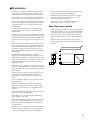
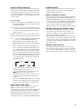
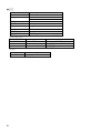
Rack Mounting Caution
If the unit is rack mounted and transported regularly,
for example, when on a tour, we recommend that the
rear of the unit be supported by fitting a pair metal
brackets, one each side. The following drawing pro-
vides the information necessary to make such brack-
ets.
Note that only one bracket is shown here and the
bracket for the other side must be bent in the opposite
direction.
86.5
20.5
3.1
4-
ø
6.5
2-R2
R2
2-R2
R5
t = 1.6
(82.1)
76.2
44.45
31.75
5.9
0
36.5
14.5
7.5
8
0
12
134
200
0

4
Cards installable on the AO8 analog output box :
LMY4-DA — DA card
AO8-DA8 analog output unit :
AO8 analog output box that has eight LMY-4-DA cards installed
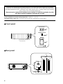
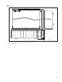
■
Front panel
■
Rear panel
Thank you for choosing the AO8 analog output box, or the AO8-DA8 analog output unit, specifically
designed for the Yamaha PM1D digital audio mixing system. The AO8 converts digital signal input from
the DSP1D/DSP1D-EX engine (controlled via the CS1D control surface) to analog signals. Up to six AO8s
can be connected to each DSP1D/DSP1D-EX.
Be sure to ask an authorized Yamaha service engineer to install the card and set up the
unit. Never perform installation and setup by yourself.
1234567
UNIT NO.
INPUT SELECTOR
A
B
POWER
ON/ OFF
8
ANALOG OUTPUT BOX
OUTPUT UNIT ID
INPUT SELECTOR
A
B
POWER
ON/ OFF
ANALOG OUTPUT BOX
1
2
3
The illustration shows the AO8
analog output box
*
75Ω
IN
BA
INPUT
ON
OFF
OUT
WORD
CLOCK
BA
INPUT
ON
OFF
OUT
WORD
CLOCK
75Ω
IN
4
5
6

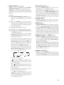
5
A
OUTPUT UNIT ID indicator
This indicator displays the ID number of the OUT-
PUT connector of the DSP unit DSP1D/DSP1D-EX
connected to the AO8. If an error occurs in the con-
nection to the DSP1D, or if the unit does not lock to
the wordclock signal, one of the following error indi-
cations appears.
Error message
E2
: The AO8 is connected to the INPUT connector of
the DSP1D/DSP1D-EX. Connect the AO8 to the
OUTPUT connector.
E3
: A cable is disconnected from the INPUT A, B, or
C connector on the rear panel, or the connection
is made incorrectly. If the connection is proper,
replace the cable.
UL
: The unit does not lock to the wordclock signal.
UC
: The control signal is not being received correctly.
“
O
.
x
.
”:(two dots and the ID number of the OUTPUT
connector on the DSP1D/DSP1D-EX)
Illuminating dots means that the AO8 is con-
nected in Mirror mode from the DSP1D/DSP1D-
EX.
If “
O
.
x
.
” lights up continuously during Mirror
mode operation, the INPUT SELECTOR switch
(
2
) setting matches the setting controlled from
the CS1D and the system is operating normally.
If the control signal from the CS1D has changed
the setting during Mirror mode operation and it
does not match the INPUT SELECTOR switch
(
2
) setting any more, this indicator changes in
the following order.
“_.
A
.” means that the control signal from the
CS1D has changed the setting to “A”
“ ” means that the control signal from the
CS1D has changed the setting to “B.”
During this time period, you can connect or dis-
connect the cable from the unselected output
connector.
If you set the INPUT SELECTOR switch so that it
matches the setting made via the control signal
from the CS1D, “
O
.
x
.
” lights up continuously.
B
INPUT SELECTOR switch
Use this switch to select an input source from the
INPUT A or B connector on the rear panel.
During the Mirror mode operation, the control signal
sent from the CS1D has priority, and the INPUT
SELECTOR switch is disabled. In this case, the OUT-
PUT UNIT ID indicator shows the status. For more
information, refer to
1
OUTPUT UNIT ID indicator.
C
POWER ON/OFF
Use this switch to turn the power to the AO8 on and
off. When the power is turned on, the OUTPUT
UNIT ID indicator lights up.
D
INPUT connectors A and B
These connectors are used to input multi-channel dig-
ital audio signals from the DSP1D/DSP1D-EX. Use
the INPUT SELECTOR switch
2
on the front panel
to select an input source (INPUT A or INPUT B). Be
sure to use the included genuine Yamaha half-pitch
68-pin cable for connection. Optional genuine
Yamaha cables in a variety of lengths are also available.
E
WORD CLOCK IN jack, ON/OFF switch
The WORD CLOCK IN jack is used to provide the
word clock to the AO8 from a clock generator or a
connected external device. Use a BNC cable with an
impedance of 75
Ω
for connection.
The WORD CLOCK ON/OFF switch is used to termi-
nate the word clock connection. Basically, if the AO8
is the last device of the word clock chain, or if nothing
is connected to the WORD CLOCK IN/OUT jacks, set
this switch to ON.
F
WORD CLOCK OUT jack
The WORD CLOCK OUT jack is used to provide
word clock from the AO8 to the connected external
device, such as a digital MTR or a DAT recorder. Use a
BNC cable with an impedance of 75
Ω
for connection.
“. .”
“ .x.”
“. .”
“ ”(
“”)

6
■
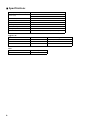
Specifications
Digital I/Os
Slots
Sampling frequency (external sync) 39.69 kHz – 50.88 kHz
Power supply
USA and Canada : 120 V, 60 Hz
Others : 230 V, 50 Hz
Power consumption 120 W
Dimensions (W
×
H
×
D) 480 mm
×
141.5
mm
×
466.8 mm
Weight 15.4 kg
Operating temperature 10 – 35˚C
Power cable length 2.1 m
Cooling fan speed always fixed
Accessories Connection cable (68-pin, D-sub, half-pitch) x 1, Length: 3m
I/O connectors Level Type
INPUT A, B RS-422 D-sub, half-pitch, 68-pin connector (female)
WORD CLOCK IN TTL/75
Ω
(ON/OFF) BNC connector
WORD CLOCK OUT TTL/75
Ω
BNC connector
Card Output
LMY4-DA Channel 1 – 4

7
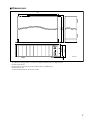
■
Dimensions
• Specifications and appearance are subject to change without notice for improvement.
• For European Model
Purchaser/User information specified in EN55103-1 and EN55103-2.
Inrush Current: 13A
Conformed Environment: E1, E2, E3 and E4.
455
466.8
480
430
132
141.5
(3U)
OUTPUT UNIT ID
INPUT SELECTOR
A
B
POWER
ON/ OFF
123456 7 8
ANALOG OUTPUT BOX
9.5
unit: mm

YAMAHA CORPORATION
Pro Audio & Digital Musical Instrument Division
P.O. Box 3, Hamamatsu, 430-8651, Japan

-DA8
ANALOG OUTPUT BOX
ANALOG OUTPUT UNIT
J

2
!

3
!
86.5
20.5
3.1
4-
ø
6.5
2-R2
R2
2-R2
R5
t = 1.6
(82.1)
76.2
44.45
31.75
5.9
0
36.5
14.5
7.5
8
0
12
134
200
0

4
1234567
OUTPUT UNIT ID
INPUT SELECTOR
A
B
POWER
ON/ OFF
8
ANALOG OUTPUT BOX
OUTPUT UNIT ID
INPUT SELECTOR
A
B
POWER
ON/ OFF
ANALOG OUTPUT BOX
1
2
3
75Ω
IN
BA
INPUT
ON
OFF
OUT
WORD
CLOCK
BA
INPUT
ON
OFF
OUT
WORD
CLOCK
75Ω
IN
4
5
6

5
1 OUTPUT UNIT ID
E2:
E3:
UL:
UC:
O
.x. x
O.x.
2
2
“. .”
“ .x.”
“. .”
“”(
“”)
O.x .
2 INPUT SELECTOR
3 POWER ON/OFF
4 INPUT A B
5 WORD CLOCK IN ON/OFF
6 WORD CLOCK OUT

6
Ω
Ω

7
455
466.8
480
430
132
141.5
(3U)
OUTPUT UNIT ID
INPUT SELECTOR
A
B
POWER
ON/ OFF
123456 7 8
ANALOG OUTPUT BOX
9.5

☎
☎
☎
☎
☎
☎
☎
☎
☎
☎
☎
☎
☎
☎
☎
☎
☎
☎
-
 1
1
-
 2
2
-
 3
3
-
 4
4
-
 5
5
-
 6
6
-
 7
7
-
 8
8
-
 9
9
-
 10
10
-
 11
11
-
 12
12
-
 13
13
-
 14
14
-
 15
15
-
 16
16


Yamaha AO8-DA8 Kullanım kılavuzu
- Tip
- Kullanım kılavuzu
diğer dillerde
- español: Yamaha AO8-DA8 Manual de usuario
- français: Yamaha AO8-DA8 Manuel utilisateur
- italiano: Yamaha AO8-DA8 Manuale utente
- svenska: Yamaha AO8-DA8 Användarmanual
- 日本語: Yamaha AO8-DA8 ユーザーマニュアル
- čeština: Yamaha AO8-DA8 Uživatelský manuál
- polski: Yamaha AO8-DA8 Instrukcja obsługi
- Deutsch: Yamaha AO8-DA8 Benutzerhandbuch
- português: Yamaha AO8-DA8 Manual do usuário
- English: Yamaha AO8-DA8 User manual
- dansk: Yamaha AO8-DA8 Brugermanual
- русский: Yamaha AO8-DA8 Руководство пользователя
- Nederlands: Yamaha AO8-DA8 Handleiding
- română: Yamaha AO8-DA8 Manual de utilizare