
MIXER
Owner’s Manual
Thank you for purchasing the YAMAHA MV800.
The MV800 is an easy to operate mixer that offers an excellent balance
between line input devices for BGM or Karaoke and microphone input.
When the hall is divided into two zones, the MV800 also offers individual
control of those two zones directly from the front panel without the need to
change the wiring making it an excellent mixer for banquet rooms, etc.
In order to get the most out of your MV800 and its excellent functions, and
to enjoy years of trouble-free use, please read this Owner’s Manual thor-
oughly before using. And please keep it, in a safe place for future reference.
Keep This Manual For Future Reference.

MV800 — Owner’s Manual
WARNING: THIS APPARATUS MUST BE EARTHED
IMPORTANT
THE WIRES IN THIS MAINS LEAD ARE COLOURED IN
ACCORDANCE WITH THE FOLLOWING CODE:
GREEN-AND-YELLOW : EARTH
BLUE : NEUTRAL
BROWN : LIVE
As the colours of the wires in the mains lead of this apparatus may
not correspond with the coloured markings identifying the terminals in
your plug, proceed as follows:
The wire which is coloured GREEN and YELLOW must be
connected to the terminal in the plug which is marked by the letter E
or by the safety earth symbol or coloured GREEN and YELLOW.
The wire which is coloured BLUE must be connected to the terminal
which is marked with the letter N or coloured BLACK.
The wire which is coloured BROWN must be connected to the
terminal which is marked with the letter L or coloured RED.
* This applies only to products distributed by YAMAHA KEMBLE
MUSIC (U.K.) LTD.

MV800 — Owner’s Manual
Important
Read the following before operating the MV800
Important 1
Warnings
• Do not place a container with liquid or small metal objects on top of this unit. Liquid or metal objects inside
this unit are a fire and electrical shock hazard.
• Do not allow water to enter this unit or allow the unit to become wet. Fire or electrical shock may result.
• Connect this unit’s power cord only to an AC outlet of the type stated in this Owner’s Manual or as marked on
the unit. Failure to do so is a fire and electrical shock hazard.
• Do not scratch, bend, twist, pull, or heat the power cord. A damaged power cord is a fire and electrical shock
hazard.
• Do not place heavy objects, including this unit, on top of the power cord. A damaged power cord is a fire and
electrical shock hazard. In particular, be careful not to place heavy objects on a power cord covered by a carpet.
• If you notice any abnormality, such as smoke, odor, or noise, or if a foreign object or liquid gets inside the unit,
turn it off immediately. Remove the power cord from the AC outlet. Consult your dealer for repair. Using the
unit in this condition is a fire and electrical shock hazard.
• Should this unit be dropped or the cabinet be damaged, turn the power switch off, remove the power plug
from the AC outlet, and contact your dealer. If you continue using the unit without heeding this instruction,
fire or electrical shock may result.
• If the power cord is damaged (i.e., cut or a bare wire is exposed), ask your dealer for a replacement. Using the
unit with a damaged power cord is a fire and electrical shock hazard.
• Except for the safety cover, never remove anything else from this device. (Please refer to page 8 about the Euro-
block connectors.) You could receive an electrical shock. If you think internal inspection, maintenance, or
repair is necessary, contact your dealer.
• Do not modify the unit. Doing so is a fire and electrical shock hazard.
• If lightning begins to occur, turn off the power switch of the unit as soon as possible, and unplug the power
cable plug from the electrical outlet.
• If there is a possibility of lightning, do not touch the power cable plug if it is still connected. Doing so may be
an electrical shock hazard.
Cautions
• When rack-mounting the unit, allow enough free space around the unit for normal ventilation. This should
be: 10 cm at the sides, 40 cm behind, and 30 cm above.
For normal ventilation during use, remove the rear of the rack or open a ventilation hole.
If the airflow is not adequate, the unit will heat up inside and may cause a fire.
• This unit has ventilation holes at the top, bottom, and sides to prevent the internal temperature rising too
high. Do not block them. Blocked ventilation holes are a fire hazard.
• Hold the power cord plug when disconnecting it from an AC outlet. Never pull the cord. A damaged power
cord is a potential fire and electrical shock hazard.
• Do not touch the power plug with wet hands. Doing so is a potential electrical shock hazard.
Operating Notes
• Using a mobile telephone near this unit may induce noise. If noise occurs, use the telephone away from the
unit.
• XLR-type connectors are wired as follows:
pin 1: ground, pin 2: hot (+), and pin 3: cold (-).
• Refer to the “Connector polarity” chart on page 7 for information on the pin wiring of the XLR connector and
phone jack.
• The performance of components with moving contacts, such switches, rotary controls, faders, and connectors,
deteriorates over time. The rate of deterioration depends on the operating environment and is unavoidable.
Consult your dealer about replacing defective components.
• Use only the specific screws that are provided with the MV800 to attach the supplied security cover. Also, after
wiring the Euro-block connectors, use the same screws that held the security cover in place when replacing the
cover.
The use of any other screws may result in damage.

MV800 — Owner’s Manual
2 MV800
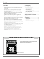
Features
• The MV800 provides 8 channels with monaural input jacks, A/B stereo
line input jacks and two sets of stereo outputs that are selectable from
the front panel.
• Monaural input jacks are equipped with an input select switch that
allows compatibility with a wide range of sources such as dynamic
microphones, condenser microphones that require an external power
source, and line level devices.
• Each monaural channel is equipped with a separate noise gate switch
that can be used to eliminate background noise.
• The mixer is equipped with a global compressor circuit that can be
applied to the monaural channels to protect the equipment from
feedback, sudden loud sounds, etc.
• The mixer is equipped with a ducker circuit on channels 1/2. This
function automatically reduces the volume level of the stereo line input
jacks when a microphone from channel 1 or 2 is used.
• Input channels 1-8 are equipped with INSERT IN/OUT jacks allowing
separate effectors to be connected to individual channels.
• Equipped with two ZONE buses, that include not only monaural and
stereo channels but also REC OUT and OUTPUT jacks, a single MV800
easily provides sound control for two rooms.
• Separate REC OUT jacks are supplied for both ZONES 1 and 2 allowing
easy recording to a tape deck.
• Along with XLR and phone jacks, Euro-block connectors are also
supplied for the main input and output jacks.
• The MV800 is equipped with a paging function for an emergency
announcement system. It is also equipped with an input jack for an
emergency announcement system’s control signal (DC24V).
• A security cover is supplied to protect switches and settings on the
control panel.
Contents
Front & Rear Panels ............................ 3
Front Panel Section ................................ 3
Stereo Channel &
Master Control Sections ..................... 4
Rear Panel Section ................................ 6
About the Accessories ........................ 8
About the MV800’s Functions ........... 9
Applications .......................................... 10
Supplement .......................................... 13
Specifications ....................................... 13
Dimensions .......................................... 15
Block and Level Diagrams .................... 16
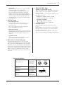
Caution: When the unit is installed in a rack
The main unit’s power switch is located on the rear panel of
the unit. When installed in a rack, please use the external
power switch on a power distributor, etc.
Power distributor, etc.

MV800 — Owner’s Manual
Front & Rear Panels 3
q
ui
y
t
r
e
w
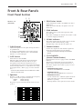
Channels 1-8
(Monaural)
Response [dB]
+5
+10
+15
–15
–10
–5
0
Frequency [Hz]
10k1k100 20k20
+20
–20
Front & Rear Panels
Front Panel Section
q GAIN Control
Adjusts the input level of the signal entering the mixer to
an optimum level.
To obtain an optimum balance between the S/N ratio
and dynamic range, adjust the level so that the PEAK
Indicator t occasionally lights.
w GATE Switch
Turns the Noise Gate ON/OFF.
When the switch is ON (>), the signal entering the
channel’s INPUT jack will only be allowed to pass
through the circuit when the designated level is ex-
ceeded. This function can be used to effectively eliminate
unwanted background noise (sounds that are lower than
the designated level). (Refer to page 9 for more informa-
tion.)
* To turn the switch ON/OFF, use an insulator that is smaller
than the size of the switch.
e Equalizer
Provides +/-15dB of control over high and low frequency
ranges at the center frequencies listed below.
HIGH : 10kHz (shelving)
LOW : 100Hz (shelving)
Frequency response is flat when the knob is at its center
position.
r ZONE Select Switch
Sends each channel’s signal to the ZONE 1 bus and/or
ZONE 2 bus.
When the switch is ON (>), the signal is sent to the
relative bus.
t PEAK Indicator
The indicator detects peaks in the signal after it has
passed the EQ.
The indicator will light red when the level reaches +17dB
to warn that clipping is imminent.
y SIGNAL Indicator
The indicator lights when the signal’s level exceeds that
of the Noise Gate’s threshold level post EQ.
The light will go off shortly after the signal is cut.
u Channel Volume
Controls the output level of the channel’s signal and
adjusts the volume balance between channels.
* The volume on channels not being used should be
lowered.
i ST CH DUCKER
(Stereo Channel Ducker)
Input channels 1 and 2 are equipped with a “DUCKER
Function”.
This function automatically decreases the ST Input
signal’s volume when the signal from channel 1 or 2
exceeds the designated level. (Refer to page 9 for more
information.)
• DUCKER ON/OFF Switch
Switches the DUCKER Function ON/OFF.
• DUCKER Indicator
Lights when the DUCKER function is activated.
• DUCKER Attenuator
Sets the volume level to which the signal from the ST
input jacks will be lowered when the DUCKER
Function is operating.
Rotating the knob to the right decreases the volume.

MV800 — Owner’s Manual
4 Front & Rear Panels
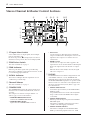
q ST Input Select Switch
Selects which of the two input signals, from ST Input
jacks A or B, will be used.
In the raised position (?), ST Input jack A is selected
while the lowered position (>) selects ST Input jack B.
w ZONE Select Switch
The same as number r on page 3.
e PEAK Indicator
Indicates peaks in the signal of the post buffer amp.
The indicator will light red when the level reaches +17dB
to warn that clipping is imminent.
r SIGNAL Indicator
The indicator will light when the signal level exceeds
-10dB in the post buffer amp.
t Channel Volume
The same as number u on page 3.
y COMPRESSOR
The COMPRESSOR controls the signal’s volume level
when the level set with the TH (Threshold) Control is
exceeded.
The Compressor is effective on input channels 1-8.
(Refer to page 9 for more information.)
• COMPRESSOR ON/OFF Switch
Switches the COMPRESSOR ON/OFF.
• COMPRESSOR Indicator
Lights when the COMPRESSOR is activated.
Stereo Channel & Master Control Sections
yo!0 !1 !3 !4 !5
tui !6!2
r
e
q
w
• TH Control
Sets the input level (Threshold level) at which the
compressor will function. Rotating the control to the
right allows the compressor to function at lower
volume levels.
• RATIO Control
Sets the ratio of compression that is applied to the
signal when it exceeds the threshold level. Rotating the
knob to the right increases the amount of compres-
sion.
When the knob is turned fully to the left, the signal
will not be compressed.
u PAGING
The PAGING function terminates all signals from each
of the INPUT channels (1-8, ST), INSERT IN and
STACK IN input jacks and only allows the signal from
the PAGING MIC/LINE input jack to be produced. This
function can also be used with a control signal from an
emergency announcement system. (Refer to page 9 for
more information.)
• PAGING GAIN Control
Controls the input sensitivity of the PAGING MIC/
LINE input jack.
An optimum balance between the S/N and dynamic
range is achieved when the PEAK indicator lights
occasionally.
• PAGING PEAK Indicator
Indicates post head amp level peaks in the PAGING
MIC/LINE signal.
The indicator will light red when the level reaches
+17dB to warn that clipping is imminent.
• PAGING SIGNAL Indicator
The indicator will light when the PAGING MIC/
LINE’s post head amp signal level exceeds -10dB.

MV800 — Owner’s Manual
Front & Rear Panels 5
• PAGING LEVEL Control
Controls the output level of the PAGING MIC/LINE
input and adjusts the volume.
i PAGING INPUT DUCKER
• PAGING TH Control
Sets the level at which the mixer switches to its
PAGING function. Rotating the knob to the right
lowers the level at which the mixer will switch to the
paging function.
• PAGING Indicator
The indicator lights when the paging function is in
use.
• PAGING ZONE Select Switch
Selects the zone to which the PAGING MIC/LINE
signal will be sent. The PAGING MIC/LINE signal is
sent to the zone output jacks (ZONE 1, 2) that are
switched ON.
o LEVEL Meter
This LED indicates the level of the output signal for each
of the ZONE output jacks (ZONE 1,2).
“0” indicates a nominal level, and the PEAK indicator
will light red to warn when clipping is imminent.
!0 ZONE Volume
Controls the volume level of the signal that is sent to the
ZONE output jacks (ZONE 1, 2).
!1 ST/MONO Select Switch
Set the switch to ST when the signal from the ST Input
jack is to be sent to the ZONE output jacks (ZONE 1, 2)
as a stereo signal. Set the switch to MONO when the L
and R channels are to be mixed as a monaural signal.
!2 ZONE 1 TO 2 Switches
Set the switch to its ON (>) position to send the signal
from ZONE 1 (pre-volume) to ZONE 2 (pre-volume). In
this case, the ZONE 1 (pre-volume) signal will be sent to
the ZONE 2 output jacks and that signal’s volume can be
adjusted with the ZONE 2 Volume control.
!3 POWER Indicator
The indicator will light when the unit’s power is ON.
!4 ZONE AFL Select Switch
Selects the signal that is sent to the PHONES jack.
Press the switch to select either ZONE 1 (?) or ZONE 2
(>).
!5 HEADPHONE Volume
Controls the signal level that is sent to the PHONES jack.
!6 PHONES Jack
This is a stereo phone type jack for connecting a pair of
headphones (nominal output/impedance of 30mW/
40Ω).
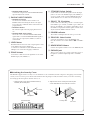
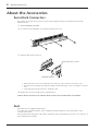
■ Attaching the Security Cover
The MV800 is supplied with a security cover for channels 1-8, the ST channel, and the compressor and paging sections. If the
security cover is needed to protect knobs and switches from being tampered with, attach the security cover after connecting
and setting up the microphones and line devices, etc.
1. Attach the post screws to the attachment holes (4
locations) on the front panel.
2. Align the holes in the security cover with the post
screws and attach the cover with the set screws.
Front panel
Post screw
Attachment hole
Security cover
Set screw

MV800 — Owner’s Manual
6 Front & Rear Panels
et
qry
w
u
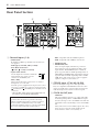
q Channel Inputs (1-8)
• INPUT Jacks
Both balanced XLR type and Euro-block connectors
are supplied.
•
XLR Type (1:Ground, 2:Hot, 3:Cold)
•
Euro-block connectors
( : Hot, : Cold, G: Ground)
• Input Select Switch
Use the Input Select Switch to match the
input with the type of mic or device
connected to the INPUT jack.
•
MIC (+48V)
This position allows the connection of a condenser
microphone, etc. to the jack.
DC+48V power is supplied between pins 2 and 1, and
pins 3 and 1 on XLR type connectors, and between the
and GND, and and GND pins on the Euro-block
connectors.
* When the MIC (+48V) setting is not needed, make sure
the switch is set to the MIC or LINE position.
Rear Panel Section
NOTE: When the switch is in the MIC (+48V)
position, there should be no problem connecting
balanced dynamic microphones or line level devices
however, hum or malfunction may occur when
connecting unbalanced devices or devices with which
the center of the transformer is ungrounded.
•
MIC: Compatible with 50-600Ω microphones.
•
LINE: Compatible with 600Ω line level devices.
• INSERT IN Jack
• INSERT OUT Jack
These are input/output jacks that are positioned
between the noise gate and channel volume of the
input channel. The INSERT IN jack is a balanced
phone type jack with a nominal input/impedance of
0dB/600Ω. The INSERT OUT jack is balanced phone
type jack with a nominal output/impedance of 0dB/
10kΩ. These jacks can be used to connect a graphic
equalizer, compressor, noise filter, etc.
w STEREO Input (ST AL/AR, BL/BR)
These are RCA phono type stereo line input jacks.
They are compatible with 600Ω line level devices. Two
devices, A and B, can be connected and selected for use
with the ST Input Select Switch on the front panel.
e STACK IN/OUT Jacks
•
STACK IN
This is an unbalanced phone type output jack with a
nominal input/impedance of 0dB/600Ω. The signal
carried by the Tip is sent to the ZONE 1 bus while the
signal that is carried by the Ring is sent to the ZONE 2
bus.
These jacks can be used as auxiliary inputs. Also, they
can be used to receive the return signal from an
external effector such as a reverb, delay, etc.

MV800 — Owner’s Manual
Front & Rear Panels 7
•
STACK OUT
This is an unbalanced phone type output jack with a
nominal input/impedance of 0dB/10kΩ.
It sends the ZONE 1 and ZONE 2 bus signals that
have passed through the compressor circuit. The
ZONE 1 signal is sent to the Tip while the ZONE 2
signal is sent to the Ring. When multiple MV800s are
connected together, this jack sends the signal to the
main MV800. It can also be used to send the signal to
an external device.
r PAGING Input
• MIC/LINE Input Jack
Connect the source device (cassette deck, etc.) or
microphone that will be used when the paging
function is in use.
This jack is compatible with 50Ω to 600Ω micro-
phones or 600Ω line level devices.
• Input Select Switch
Selects the type of microphone or device connected to
the MIC/LINE input jack. This switch functions in the
same manner as the Input Channel’s Input Select
Switch q.
• CONTROL IN Jack
This is the input jack for the emergency announce-
ment system’s control signal (DC24V).
t REC OUT (1L/1R, 2L/2R) Jacks
With an external DAT recorder or cassette recorder
connected to these jacks, you can record the same signal
that is sent from the ZONE OUT jacks. The signal from
ZONE 1 is sent to the 1L and 1R jacks while the ZONE 2
signal is sent to the 2L and 2R jacks. The signal sent from
these jacks is not affected by the ZONE volume controls.
Make recording level adjustments on the recording
device. Also, the ZONE 1 TO 2 switch is ineffective with
these jacks.
y ZONE OUTPUT Jacks
(ZONE 1 L/R, ZONE 2 L/R)
These jacks deliver the stereo output of the mixed signal
and are connected to a power amplifier, etc. that drives
the main speakers.
Two types of jacks are provided; balanced XLR type and
Euro-block connectors.
•
XLR type (1: Ground, 2: Hot, 3: Cold)
Nominal output/impedance +4dB/600Ω
•
Euro-block connector
(
: Hot, : Cold, G: Ground)
Nominal output/impedance +4dB/600Ω
u POWER Switch
When the switch is in the ON position, the unit is
powered.
When turning the power ON, first turn on the MV800,
then turn on the power amp or powered speakers that
are connected to the device.
Also, when turning the power OFF, turn off the power
amp or powered speakers before turning off the MV800.
Connector polarity
INPUT, ZONE OUT
Pin 1: ground
Pin 2: hot (+)
Pin 3: cold (–)
INSERT IN
INSERT OUT
Tip: hot (+)
Ring: cold (–)
Sleeve: ground
STACK IN
STACK OUT
Tip: ZONE 1
Ring: ZONE 2
Sleeve: ground
PHONES
TipSleeve
Ring
Tip: L
Ring: R
Sleeve: ground
INPUT OUTPUT

MV800 — Owner’s Manual
8 About the Accessories
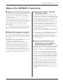
About the Accessories
Euro-block Connectors
If you decide to use Euro-block connectors, please use the supplied connectors and attach as shown in the
illustration below.
q Turn the POWER switch OFF.
w Loosen the screws holding the cover in place and remove the cover.
Euro-block connector
e Attach the Euro-block connectors.
1. If the hole for the wire is closed, turn the screw on the top of the connector to the left to open.
2. Insert the wires according to the jack’s pole display, and turn the upper screw to the right to secure the
wire.
3. Connect the Euro-block connector to the mixer’s jack.
r Replace the cover and re-attach it in its original location.
Caution:
Electric shock may occur if the Euro-block connectors are used without the cover attached.
Feet
Four rubber feet are supplied with the mixer.
According to the orientation that the device is installed, attach the rubber feet to the surface that is at the
“bottom” of the mixer.
After wiping any dust and grime on the surface of the mixer, remove the adhesive’s protective cover on the top of
the feet and attach to the mixer.
Secure with a minus (-) driver.

MV800 — Owner’s Manual
About the MV800’s Functions 9
About the MV800’s Functions
■ About the NOISE GATE Function
An unused microphone often picks up unwanted background
noise. One way to prevent the problem is to turn the
microphone off or set its channel volume on the MV800 to
“0” when necessary. An easier way to solve the problem is to
use the NOISE GATE.
The mixer will automatically accept input from the micro-
phone only when the designated level is exceeded. If the level
is not exceeded (such as that produced by background noise)
the microphone will not operate. Effective use of this
function eliminates unnecessary mixer operation and
controls feedback.
Press the GATE Switch to the ON (>) position to activate.
Also, we recommend that the switch be set to the OFF (?)
position when someone is talking with a quiet voice.
■ About the Compressor Function
When someone is speaking or singing and suddenly their
voice becomes loud can be irritating. The volume must be
reduced but by the time you make the necessary adjustment,
its already too late. In such a case, the Compressor Function
is very useful.
This function is used to control the signal’s output level when
it’s input level exceeds a designated amount.
Set the Compressor ON/OFF switch to “ON”.
The input level setting that determines from when the
compressor will function is set with the TH (Threshold)
control. Also, the setting that determines the ratio of
compression used to keep the signal’s volume under control
is set with the RATIO control. When the RATIO control is
rotated fully to the left, the output volume will not be
controlled (minimum compression ration 1:1), as the control
is rotated to the right, the amount of compression applied to
the signal increases (maximum compressions ratio ∞:1)
■ About the STEREO CHANNEL
DUCKER Function
When BGM is playing in the room, and the MC or a guest
starts to speak, it is often difficult to hear the speaker over the
music. In this case, it is necessary to reduce the BGM volume,
raise the microphone’s volume or both. If so, it is impossible
to safely leave the mixer for any length of time. In such cases,
the Stereo Channel Ducker Function is very useful.
This function automatically reduces the volume of the BGM
source that is connected to the ST Input jacks (A/B) when a
signal enters Channel 1 or 2 through its microphone.
However, the Stereo Channel Ducker Function can only be
used in conjunction with Channels 1 and 2, not with sources
connected to Channels 3-8.
Shortly after the source from Channel 1 or 2 is terminated,
the volume of the BGM source will be returned to its original
level.
To setup the Ducker, set the ST CH DUCKER Switch, located
between Channels 1 and 2 on the front panel, to its “ON”
position. Use the Attenuator, located above the ST CH
DUCKER ON/OFF Switch, to set the level to which the
BGM’s volume will be reduced. Rotate the knob to the right
to reduce the volume level.
■ About the PAGING Function
(Input Ducker for Emergency
Announcement Systems)
This function terminates the signals from each of the INPUT
Channels (1-8, ST) as well as the INSERT IN and STACK IN
input jacks to give priority to the signal from the mic/line
source that is connected to the PAGING MIC/LINE Input
jack.
If a cassette deck or microphone for emergency announce-
ments is connected to the PAGING MIC/LINE Input jack, the
microphone or tape deck can be given priority for announce-
ments in the event of an emergency. A PAGING CONTROL
IN jack is also supplied on the Rear Panel that is compatible
with a DC24V control signal for emergency announcement
systems.
The GAIN control is used to set the PAGING MIC/LINE
input’s gain setting. Use the LEVEL control to set the volume.
Use the TH (Threshold) control to set the input level that
determines from when the Paging function will operate.
Rotate the TH control to the right allows the Paging function
to operate from lower volume levels.
The Paging function can be set ON/OFF in ZONEs 1 and 2
separately.

MV800 — Owner’s Manual
10 Applications
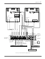
Applications
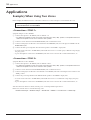
Example) When Using Two Zones
In this example, the MV800 is used to control the sound in two rooms, a banquet room and a Karaoke room.
Before making any connections, make sure that power switches on the MV800 and any
connected devices are turned OFF.
<Connections: ZONE 1>
Assign the banquet room to ZONE 1.
q Connect microphones to the INPUT jacks of channels 1-4.
* If a condenser microphone is used, set the Input Select Switch to its “MIC(+48V)” position, if a microphone other than a
condenser microphone is used, set the switch to its “MIC” position.
w Connect a reverb unit between the INSERT IN/OUT jacks on Channels 3 and 4.
e Connect a DVD player for Karaoke to the ST channel’s AL/AR INPUT jacks, and a CD player for BGM to the ST
BL/BR INPUT jacks.
r Connect the main power amp that drives the main speakers to the ZONE 1 output jacks.
* A cassette deck connected to the REC OUT jacks 1L/1R can be used to record the party or Karaoke songs sung by
the party guests.
* A pair of headphones connected to the PHONES jack can be used to monitor the overall volume balance, etc.
<Connections: ZONE 2>
Assign the Karaoke room to ZONE 2.
q Connect microphones to the INPUT jacks of channels 5 and 6.
* If a condenser microphone is used, set the Input Select Switch to its “MIC(+48V)” position, if a microphone other than a
condenser microphone is used, set the switch to its “MIC” position.
w Connect a reverb unit between the INSERT IN/OUT jacks on channels 5 and 6.
e Connect a DVD player for Karaoke to the Channel 7 and 8 INPUT jacks and set their Input Select Switches to the
“LINE” position.
r Connect the power amp that drives the ZONE 2 main speakers to the ZONE 2 output jacks.
* A cassette deck connected to the REC OUT jacks 2L/2R can be used to record Karaoke songs sung by the party
guests.
* A pair of headphones connected to the PHONES jack can be used to monitor the overall volume balance, etc.
After all connections have been made, turn the power on starting with the input devices.
In this case, turn the devices on in the following order.
Karaoke DVD Player → BGM CD Player → Reverb Unit → MV800 → Cassette Deck → Power Amp

MV800 — Owner’s Manual
Applications 11
ZONE 1 ZONE 2
PHONES
REC OUT
1L, 1R
REC OUT
2L, 2R
INPUT
ST INPUT
B
A
INSERT OUT
ZONE 1
OUTPUT
ZONE 2
OUTPUT
INSERT IN
INSERT OUT
INSERT IN
INSERT OUT
INSERT IN
INSERT OUT
INSERT IN
Power Amp + Speakers
Microphone
for MC
Microphone for
Speakers
Microphone for
Karaoke
Power Amp + Speakers
DVD Player
for Karaoke
Set the ZONE 1
switch to “ON” on
CH 1-4 only
ST CH DUCKER
Switch = ON
Reverb Unit Reverb Unit
Set the ZONE 2
switch to “ON” on
CH 5-8 only
Set the ZONE 1 switch
to “ON” on ST CH only
ZONE AFL
Select Switch
Select the zone
you want to
monitor.
Set the 1 TO 2
Switch OFF
Cassette Deck for
recording ZONE 1
Cassette Deck for
recording ZONE 2
* If necessary, setup the compressor or paging functions.
CD Player
for BGM
DVD Player
for Karaoke
Microphone for
Karaoke

MV800 — Owner’s Manual
12 Applications
<Setting: ZONE 1>
● Channel 1-4 Settings
1. Make the following settings. Channel Volume = <,
Gate Switch = ON (>), ZONE Select Switch = only set
“1” to ON (>), ZONE 1’s ZONE Volume = <,
ST/MONO Select Switch = “ST”.
2. Adjust the GAIN control so that the PEAK Indicator
lights when you speak loudly into the microphone.
3. If necessary, use the equalizer (LO, HI) to adjust sound
quality.
● ST Channel Settings
1. Make the following settings. Channel Volume = <,
ZONE Select Switch = only set “1” to ON (>).
2. Set the ST Input Select Switch to “A” (?) and playback a
DVD with the Karaoke DVD player. Adjust the DVD
player’s output volume so that the PEAK Indicator lights
when the DVD player plays a louder passage.
3. Set the ST Input Select Switch to “B” (>) and adjust the
CD player’s output volume in the same manner as the
DVD player.
● Overall Controls
• We recommend that the compressor be switched “ON”.
Use the RATIO and TH controls to adjust the amount of
compression.
• Set the Stereo Channel DUCKER Switch to “ON” and
adjust the attenuator while producing some sound
through the system.
• Use the Volume Control for each channel to adjust the
balance between the channels.
• Use the ZONE 1 Volume to adjust the overall output
level. Adjust the level so that the level meter’s PEAK lamp
lights when a large signal is present. Use the volume
control on the power amp to adjust the volume delivered
by the speakers.
• If necessary, setup the PAGING system.
• Connect a pair of headphones to the PHONES jack and
set the ZONE AFL Select Switch to “ZONE 1 AFL” (?)
to monitor the final output.
<Setting: ZONE 2>
● Channel 5 and 6 Settings
1. Make the following settings. Channel Volume = <,
Gate Switch = ON (>), ZONE Select Switch = only set
“2” to ON (>), ZONE 2 ZONE Volume = <,
ST/MONO Select Switch = “ST”.
2. Adjust the GAIN control so that the PEAK Indicator
lights when you speak loudly into the microphone.
3. If necessary, use the equalizer (LO, HI) to adjust sound
quality.
● Channel 7 and 8 Settings
1. Make the following settings. Channel Volume = <,
Gate Switch = ON (>), ZONE Select Switch = only set
“2” to ON (>).
2. Playback a DVD with the Karaoke DVD player. Adjust
the DVD player’s output volume so that the PEAK
Indicator lights when the DVD player plays a louder
passage.
3. If necessary, use the equalizer (LO, HI) to adjust sound
quality.
● Overall Controls
• Use the Volume Control for each channel to adjust the
balance between the channels.
• Use the ZONE 2 Volume to adjust the overall output
level. Adjust the level so that the level meter’s PEAK lamp
lights when a large signal is present. Use the volume
control on the power amp to adjust the volume delivered
by the speakers.
• Connect a pair of headphones to the PHONES jack and
set the ZONE AFL switch to “ZONE 2 AFL” (>) to
monitor the overall output.

MV800 — Owner’s Manual
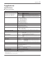
Frequency response (ZONE OUTPUT) 20Hz—20kHz 0+1dB, -3dB @+4dB, 600Ω (INPUT GAIN Control at minimum level)
Total harmonic distortion (ZONE OUTPUT) <0.1% (THD+N) @+14dB, 20Hz—20kHz, 600Ω
Hum & Noise -128dB Equivalent input noise
-97dB Residual output noise
-64dB (68dB S/N) ZONE OUT:
Master volume and one channel volume at nominal level.
-92dB (96dB S/N) ZONE OUT:
Master volume at nominal level, all channel assign switches
OFF.
Maximum voltage gain 60dB INPUT (MIC) to INSERT OUT
16dB INSERT IN to ZONE OUT
76dB INPUT (MIC) to ZONE OUT
66dB INPUT (MIC) to STACK OUT
10dB STACK IN to ZONE OUT
58.2dB INPUT (MIC) to REC OUT
23.8dB ST INPUT to ZONE OUT
76dB PAGING INPUT to ZONE OUT
Monaural input pad switch (LINE) 26dB
Monaural input gain control 44dB variable
Crosstalk at 1kHz -70dB adjacent input
-70dB input to output (CH INPUT)
-50dB between L and R (ST CH INPUT)
Monaural input equalizer’s characteristics ±15dB Maximum
HIGH 10kHz shelving
LOW 100Hz shelving
* Turn over/Roll off frequency of shelving: 3dB below maximum variable level.
Paging input pad switch (LINE) 26dB
Paging input gain control 44dB variable
Monaural input indicator PEAK (red): Each channel, the indicator will light when the post EQ signal
exceeds +17dB.
SIGNAL (green): Each channel, the indicator will light when the post EQ signal level
exceeds that of the noise gate’s threshold level.
Stereo input indicator PEAK (red): The indicator will light when the post buffer amp signal level exceeds
+17dB.
SIGNAL (green): The indicator will light when the post buffer amp signal level exceeds
-10dB.
Compressor indicator Orange: When the compressor is activated the indicator will light.
Stereo channel ducker indicator Orange: When the Stereo Channel Ducker is activated the indicator will light.
Paging indicator PEAK (red): The indicator will light when the post head amp signal level
exceeds +17dB.
SIGNAL (green): The indicator will light when the post head amp signal level
exceeds -10dB.
PAGING ON (Orange): When the ZONE Input Ducker is ON the indicator will light.
Level meters 5 points (PEAK, +6, 0, -5, -10) x 2, 0=+4dB ZONE OUT @600Ω
Phantom power +48V (balanced)
Accessories • Feet x 4
• 3-pin Euro-block connectors x 14
• Security Cover Set
(Security Cover, Post Screws x4, Set Screws x4)
Power supply USA and Canadian: 120V AC 60Hz
General: 230V AC 50Hz
Power consumption 45W
Dimensions (W x H x D) 479 x 88 x 325 mm (without accessories)
Weight 7.2kg
For European Model 0dB=0.775Vrms
Purchaser/User Information specified in EN55103-1 and EN55103-2.
Inrush Current: 7A
Conformed Environment: E1, E2, E3 and E4
Supplement 13
Supplement
Specifications
■ General specifications
(Rs=150Ω, 20Hz—20kHz, INPUT GAIN Control=Max.,
INPUT PAD=OFF, Input Sensitivity=-60dB)
* Measured with 12.7kHz, 6dB/oct. low pass filter.
(Equivalent to 20kHz, ∞dB/oct. filter.)

MV800 — Owner’s Manual
Input
PAD
GAIN Input Nominal
Input level
Connector type
connectors
Control impedance impedance
Sensitivity *1 Nominal
Max. before clipping
MIC
MAX
50-600Ω
-72 dB (0.195mV) -60 dB (0.775mV) -40 dB (7.75mV)
CH INPUT
LINE
3kΩ
mics &
-46 dB (3.88mV) -34 dB (15.5mV) -14 dB (155mV)
XLR-3-31 type *2
(1-8)
MIC
MIN
600Ω lines
-28 dB (30.9mV) -16 dB (123mV) +4 dB (1.23V)
Euro-block connector *2
LINE -2 dB (0.616V) +10 dB (2.45V) +30 dB (24.5V)
ST INPUT [L, R] (A, B) 10kΩ 600Ω lines -22 dBV (79.4mV) -10 dBV (316mV) +10 dBV (3.16V) RCA phono jack *3
MIC
MAX
50-600Ω
-72 dB (0.195mV) -60 dB (0.775mV) -40 dB (7.75mV)
PAGING
LINE
3kΩ
mics &
-46 dB (3.88mV) -34 dB (15.5mV) -14 dB (155mV)
Euro-block connector *2
MIC
MIN
600Ω lines
-28 dB (30.9mV) -16 dB (123mV) +4 dB (1.23V)
LINE -2 dB (0.616V) +10 dB (2.45V) +30 dB (24.5V)
CH INSERT IN (1-8) 10kΩ 600Ω lines -12 dB (195mV) 0 dB (0.775V) +20 dB (7.75V) Phone jack (TRS) *2
STACK IN [ZONE1, ZONE2] 10kΩ 600Ω lines -6 dB (388mV) 0 dB (0.775V) +20 dB (7.75V) Phone jack (TRS) *3
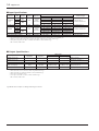
14 Supplement
■ Input Specifications
*1 Input sensitivity: the lowest level that will produce the nominal output level when the unit is set to maximum gain.
*2 XLR type connector, Euro-block connector, phone jack (TRS) (T=Hot, R=Cold, S=Gnd): balanced type.
*3 RCA phono jack, phone jack (TRS) (T=ZONE 1, R= ZONE 2, S=Gnd): unbalanced type.
• 0dB=0.775Vrms, 0dBV=1Vrms
■ Output Specifications
Output connectors
Output Nominal
Output level
Connector type
impedance impedance
Nominal
Max. before clipping
ZONE 1 OUT [L, R]
150Ω 600Ω lines +4 dB (1.23V) +24 dB (12.3V)
XLR-3-32 type *1
ZONE 2 OUT [L, R] Euro-block connector *1
CH INSERT OUT (1-8) 150Ω 10kΩ lines 0 dB (0.775V) +20 dB (7.75V) Phone jack (TRS) *2
STACK OUT 150Ω 10kΩ lines 0 dB (0.775V) +20 dB (7.75V) Phone jack (TRS) *3
REC 1 OUT [L, R]
600Ω 10kΩ lines -10 dBV (316mV) +10 dBV (3.16V) RCA phono jack *4
REC 2 OUT [L, R]
PHONES 100Ω 40Ω phones 30mW 75mW Stereo phone jack (TRS) *5
*1 XLR type connector, Euro-block connector: balanced type.
*2 Phone jack (TRS) (T=Hot, R=Cold, S=Gnd): impedance balanced type.
*3 Phone jack (TRS) (T=ZONE 1, R=ZONE 2, S=Gnd): unbalanced type.
*4 RCA phono jack: unbalanced type.
*5 Stereo phone jack (TRS) (T=L, R=R, S=Gnd): unbalanced type.
• 0dB=0.775Vrms, 0dBV=1Vrms
Specifications are subject to change without prior notice.

MV800 — Owner’s Manual
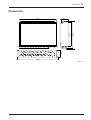
Supplement 15
429 87.5
479
88
301
337
325
Units: mm
Dimensions

MV800 — Owner’s Manual
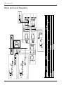
16 Supplement
+30dB
+20dB
+10dB
0dB
–10dB
–20dB
–30dB
–40dB
–50dB
–60dB
PHONES[30mW@40ohms]
PHONES
LEVEL
ZONE1 OUT
ZONE2 OUT[+4dB]
Max. Before Clip
REC OUT[-10dBV]
ZONE
LEVEL
PAGING
LEVEL
ST INPUT [-10dBV]
CH IN
LEVEL
Max. Before Clip
Max. Before Clip
CH INSERT OUT [0dB] CH INSERT IN[0dB]
CH INPUT
GAIN:MIN PAD:LINE[+10dB]
CH INPUT
GAIN:MIN PAD:MIC[-16dB]
CH INPUT
GAIN:MAX PAD:LINE[-34dB]
CH INPUT
GAIN:MAX PAD:MIC[-60dB]
+30dB
+20dB
+10dB
0dB
-10dB
-20dB
-30dB
-40dB
-50dB
-60dB
PAGING
GAIN:MIN PAD:LINE[+10dB]
ST IN
LEVEL
STACK IN[0dB]
STACK OUT[0dB]
PAGING
GAIN:MIN PAD:MIC[-16dB]
PAGING
GAIN:MAX PAD:LINE[-34dB]
PAGING
GAIN:MAX PAD:MIC[-60dB]
BA
BA
ZONE2
AFL
LEVEL
[-6dB]
[0dB]
PHONES
[30mW@40ohms]
ZONE1 OUT
[+4dB]
L
R
+
-
G
+
-
G
ZONE1 LEVEL
[-6dB]
BA
BA
1 TO 2
ZONE2 LEVEL
[-6dB]
BA
[0dB]
BA
ZONE2 OUT
[+4dB]
L
R
+
-
G
+
-
G
Relay
Relay
ST/
MONO
ST
ST
M
M
SUM
SUM
INV
INV
[0dB]
REC2 OUT
[-10dBV]
L
R
ST/
MONO
ST
ST
M
M
SUM
SUM
INV
INV
REC1 OUT
[-10dBV]
L
R
LEVEL
[-6dB]
[0dB]
BA
+
-
G
PEAK
SIGNAL
CONTROL IN
PAGING ON
TH
OFF
OFF
OFF
OFF
ON
ON
ON
ON
PAGING ON
ZONE1 DUCKER
ZONE2 DUCKER
[0dB]
PAD
HA
PAGING
MIC
[-60~-16dB]
LINE
[-34~+10dB]
+
-
G
MIC +48V
MIC
LINE
GAIN
[-60~-16dB]
[-34~+10dB]
+48V
STACK OUT
[0dB]
SUM
SUM
COMP
CHANNEL
COMP
OFF
COMP
BA
BA
OFF
OFF
ON
ON
ON
RATIO
TH
STACK IN
[0dB]
ZONE1
ZONE2
CV GEN.
ATT
OFF
ON
OFF
ON
ST CH
DUCKER
INSERT OUT
[0dB]
[0dB]
BA
LEVEL
[-6dB]
[0dB]
ZONE1
ZONE2
NOISE GATE
PEAK
SIGNAL
GATE
OFF
ON
INSERT IN
[0dB]
BA
CH INPUT
(CH1)
MIC
[-60~-16dB]
LINE
[-34~+10dB]
GAIN
[-60~-16dB]
[-34~+10dB]
PAD
HA
MIC +48V
MIC
LINE
+48V
[0dB]
2-Stage EQ
Lo
Hi
+
-
G
CH INPUT
(CH2 : Same as CH1)
NOISE GATE
PEAK
SIGNAL
GATE
OFF
ON
INSERT IN
[0dB]
BA
INSERT OUT
[0dB]
[0dB]
BA
LEVEL
[-6dB]
[0dB]
ZONE1
ZONE2
ST INPUT A
[-10dBV]
ST INPUT B
[-10dBV]
BA
BA
L
L
R
R
A/B
PEAK
SIGNAL
[0dB]
BA
BA
[0dB]
VCA
VCA
LEVEL
[-6dB]
[0dB]
ZONE1
ZONE2
ZONE1
ZONE2
CH INPUT
(CH3)
MIC
[-60~-16dB]
LINE
[-34~+10dB]
CH INPUT
(CH4~8 : Same as CH3)
+
-
G
GAIN
[-60~-16dB]
[-34~+10dB]
PAD
HA
MIC +48V
MIC
LINE
+48V
[0dB]
2-Stage EQ
Lo
Hi
Block and Level Diagrams

MV800 — Owner’s Manual

YAMAHA CORPORATION
Pro Audio & Digital Musical Instrument Division
P.O. Box 3, Hamamatsu, 430-8651, Japan
V627640 R1 1 CP 20
NP Printed in Taiwan
-
 1
1
-
 2
2
-
 3
3
-
 4
4
-
 5
5
-
 6
6
-
 7
7
-
 8
8
-
 9
9
-
 10
10
-
 11
11
-
 12
12
-
 13
13
-
 14
14
-
 15
15
-
 16
16
-
 17
17
-
 18
18
-
 19
19
-
 20
20


diğer dillerde
- español: Yamaha MV800 Manual de usuario
- français: Yamaha MV800 Manuel utilisateur
- italiano: Yamaha MV800 Manuale utente
- svenska: Yamaha MV800 Användarmanual
- čeština: Yamaha MV800 Uživatelský manuál
- polski: Yamaha MV800 Instrukcja obsługi
- Deutsch: Yamaha MV800 Benutzerhandbuch
- português: Yamaha MV800 Manual do usuário
- English: Yamaha MV800 User manual
- dansk: Yamaha MV800 Brugermanual
- русский: Yamaha MV800 Руководство пользователя
- Nederlands: Yamaha MV800 Handleiding
- română: Yamaha MV800 Manual de utilizare