Hitachi CL 14DSL Handling Instructions Manual
- Kategori
- Elektrikli aletler
- Tip
- Handling Instructions Manual
Bu kılavuz aynı zamanda aşağıdakiler için de uygundur:

Cordless Stud Cutter
Akku-gewindestangentrenner
∂·Ó·ÊÔÚÙÈ˙ÔÌÂÓÔÛ ÎÔÊÙËÛ ÓÙÈ˙·Û
Bateryjne nożyce do prętów gwintowanych
Akkus menetes rudazat daraboló
Akku střihač závitových tyčí
Akülü saplama kesici
Masina de taiat bolturi cu acumulator
Akumulatorski rezalnik navojnih palic
Akumulátorová rezačka tyčí
Бездротовий різак штифтів
AÍÍyÏyÎÓÚopÌêÈ peÁäËÍ åÔËÎeÍ
Read through carefully and understand these instructions before use.
Diese Anleitung vor Benutzung des Werkzeugs sorgfältig durchlesen und verstehen.
¢È·‚¿ÛÙ ÚÔÛÂÎÙÈο Î·È Î·Ù·ÓÔ‹ÛÂÙ ·˘Ù¤˜ ÙȘ Ô‰ËÁ›Â˜ ÚÈÓ ÙË ¯Ú‹ÛË.
Przed użytkowaniem należy dokładnie przeczytać niniejszą instrukcję i zrozumieć jej treść.
Használat előtt olvassa el figyelmesen a használati utasítást.
Před použitím si pečlivě přečtěte tento návod a ujistěte se, že mu dobře rozumíte.
Aleti kullanmadan önce bu kılavuzu iyice okuyun ve talimatları anlayın.
Înainte de utilizare, citiţi cu atenţie și înţelegeţi prezentele instrucţiuni.
Pred uporabo natančno preberite in razumite ta navodila.
Pred použitím si dôkladne tieto pokyny prečítajte a pochopte ich.
Будь ласка, прочитайте інструкції і перевірте себе, чи все зрозуміло, перш ніж користуватися приладом.
BÌËÏaÚeÎëÌo ÔpoäÚËÚe ÀaÌÌyï ËÌcÚpyÍáËï Ôo íÍcÔÎyaÚaáËË ÔpeÊÀe äeÏ ÔoÎëÁoÇaÚëcÓ ËÌcÚpyÏeÌÚoÏ.
Handling instructions
Bedienungsanleitung
√‰ËÁ›Â˜ ¯ÂÈÚÈÛÌÔ‡
Instrukcja obsługi
Kezelési utasítás
Návod k obsluze
CL14DSL
CL 14DSL
•
CL 18DSL
Kullanım talimatları
Instrucţiuni de utilizare
Navodila za rokovanje
Pokyny na manipuláciu
lнструкції щодо поводження з пристроєм
àÌcÚpyÍáËÓ Ôo íÍcÔÎyaÚaáËË
001CoverF_CL14-18DSL_EE 4/23/14, 16:231

1
B
B
B
C
E
D
5
4
3
2
1
2
7
8
9
6
1
A
1
0
I
J
H
K
F
G
H
Q
P
K
R
A
0
1
M
N
O
L
<UC18YRSL> <UC18YFSL>
1 2
3 4
5 6
7 8
003Table_CL14-18DSL_EE 4/23/14, 16:261

2
R
K
S
P
P
U
T
G
V
W
X
B
P
[
\
G
R
b
Y
Z
` a
]
9 10
11 12
13 14
15 16
003Table_CL14-18DSL_EE 4/23/14, 16:262

3
English Deutsch ∂ÏÏËÓÈο Polski
1
2
3
4
5
6
7
8
9
0
A
B
C
D
E
F
G
H
I
J
K
L
M
N
O
P
Q
R
S
T
U
V
W
X
Y
Z
[
\
]
^
a
b
Rechargeable battery
Latch
Battery cover
Terminals
Ventilation holes
Handle
Push
Insert
Pull out
Charger
Pilot lamp
Forward/reverse switching
button
Cutting
Lock
Reverse
Bracket (A) (movable side)
Hex. socket hd. bolt
Spacer (used only with
M6, M8 or M10)
Side without notch
Notch side
Bracket (B) (fixed side)
Stud guide
Dial
Screw size display
Mark
Stud
Guard section
Cutter
Correctly mesh
Fixed length guide
(First cut the stud to the
required length)
Stud attachment hole
Necessary length
Stud suspended from the
ceiling
Trigger switch
Hook
Latch
Grip
Entrance
Pliers
Remaining battery
indicator switch
Remaining battery
indicator lamp
Hex. bar wrench
Akumulator
Zapadka
Pokrywa komory
akumulatora
Styki
Otwory wentylacyjne
Rączka
Wcisnąć
Włóż/wprowadź
Wyciągnij
Ładowarka
Lampka kontrolna
Przełącznik przesuwu w
przód/w tył
Przecinanie
Blokada
Rezerwa
Wspornik (A) (strona
ruchoma)
Gniazdo śruby sześciokątnej
Podkładka (używana tylko w
przypadku M6, M8 lub M10)
Strona bez wcięcia
Strona z wcięciem
Wspornik (B) (strona
nieruchoma)
Strona pręta gwintowanego
Pokrętło
Oznaczenie rozmiaru śruby
Symbol
Pręt gwintowany
Osłona
Nożyce
Prawidłowe zazębienie
Wzór (należy najpierw
przyciąć jeden pręt na
pożądaną długość)
Otwór mocowania pręta
Pożądana długość
Pręt zawieszony pionowo
Przycisk spustowy
Haczyk
Zaczep
Uchwyt
Wejście
Obcęgi
Przełącznik wakaźnika
pozostałej energii baterii
Lampka wakaźnika
pozostałej energii baterii
Klucz sześciokątny
Aufladbare Batterie
Verriegelung
Batterieabdeckung
Anschlüsse
Belüftungslöcher
Handgriff
Drücken
Einsatz
Herausziehen
Ladegerät
Kontrollampe
Vorwärts/Rückwärts-
Schalter
Schneiden
Schließen
Umkehren
Klammer (A) (bewegliche
Seite)
Sechskantkopf-schraube
Distanzstück (nur mit M6,
M8 oder M10 verwendet)
Seite ohne Kerbe
Nutenseite
Klammer (B) (feste seite)
Stangenführung
Drehregler
Stangengröße-Anzeige
Markierung
Stange
Schutzteil
Schneider
Richtiger Eingriff
Feste Längenführung
(zuerst ie stange auf
richtige Länge zuschneiden)
Stangenansetzloch
Erforderliche Länge
An der Decke befestigte
Stange
Auslöserschalter
Haken
Verriegelung
Griff
Einführung
Zange
Ladezustand-
Anzeigeschalter
Ladezustand-
Kontrollleuchte
Sechskantschlüssel
∂·Ó·ÊÔÚÙÈ˙fiÌÂÓË Ì·Ù·Ú›·
ª¿Ó‰·ÏÔ
∫¿Ï˘ÌÌ· Ì·Ù·Ú›·˜
¶fiÏÔÈ
√¤˜ ÂÍ·ÂÚÈÛÌÔ‡
ÃÂÚÔ‡ÏÈ
™ÚÒÍÂ
∂ÈÛ¯ˆÚ‹ÛÙÂ
∆Ú·‚‹ÍÙ ¤Íˆ
ºÔÚÙÈÛÙ‹˜
¢ÔÎÈÌ·ÛÙÈ΋ Ï¿Ì·
∫Ô˘Ì› ÂÓ·ÏÏ·Á‹˜ ÂÌÚfi˜/
›Ûˆ ı¤Û˘
∫Ô‹
∫Ï›‰ˆÌ·
™˘ÁÎÚ¿ÙËÛË
µÚ·¯›ÔÓ·˜ (A) (ÎÈÓËÙ‹
ÏÂ˘Ú¿)
ªÔ˘ÏfiÓÈ ¿ÏÏÂÓ
∞ÔÛÙ¿Ù˘ (¯ÚËÛÈÌÔÔÈ›ٷÈ
ÌfiÓÔ ÌÂ Ù· M6, M8 ‹ M10)
¶ÏÂ˘Ú¿ ¯ˆÚ›˜ ÂÁÎÔ‹
¶ÏÂ˘Ú¿ ÂÁÎÔ‹˜
µÚ·¯›ÔÓ·˜ (µ) (ÛÙ·ıÂÚ‹
ÏÂ˘Ú¿)
¶ÏÂ˘Ú¿ ÓÙ›˙·˜
∫·ÓÙÚ¿Ó
∞Ó·ÁÚ·Ê‹ ÌÂÁ¤ıÔ˘˜ ‚›‰·˜
™ËÌ¿‰È
¡Ù›˙·
¶ÚÔÛٷ٢ÙÈÎfi ÙÌ‹Ì·
∫fiÊÙ˘
™ˆÛÙ‹ Û˘Ó·ÚÌÔÁ‹
√‰ËÁfi˜ ÛÙ·ıÂÚÔ‡ Ì‹ÎÔ˘˜
(¶ÚÒÙ· Îfi„ÙÂ ÙËÓ ÓÙ›˙·
ÛÙÔ ÂÈı˘ÌËÙfi Ì‹ÎÔ˜)
√‹ ÚÔÛ¿ÚÙËÛ˘ ÓÙ›˙·˜
∞·ÈÙÔ‡ÌÂÓÔ Ì‹ÎÔ˜
¡Ù›˙· ·Ó·ÚÙË̤ÓË ·fi ÙËÓ
ÔÚÔÊ‹
¢È·ÎfiÙ˘ ÂÓÂÚÁÔÔ›ËÛ˘
°¿ÓÙ˙Ô˜
∞ÛÊ¿ÏÂÈ·
§·‚‹
∂›ÛÔ‰Ô˜
¶¤ÓÛ·
¢È·ÎfiÙ˘ ¤Ó‰ÂÈ͢ ˘fiÏÔÈÔ˘
ÊÔÚÙ›Ô˘ Ì·Ù·Ú›·˜
∂Ó‰ÂÈÎÙÈ΋ Ï˘¯Ó›· ˘fiÏÔÈÔ˘
ÊÔÚÙ›Ô˘ Ì·Ù·Ú›·˜
∂Í·ÁˆÓÈÎfi ÎÏÂȉ›
003Table_CL14-18DSL_EE 4/23/14, 16:263

4
Magyar Čeština Türkçe Română
1
2
3
4
5
6
7
8
9
0
A
B
C
D
E
F
G
H
I
J
K
L
M
N
O
P
Q
R
S
T
U
V
W
X
Y
Z
[
\
]
^
a
b
Os tölthető akkumulátor
Retesz
Akkumulátorfedél
Csatlakozók
Szellőzőnyílások
Markolat
Benyomni
Bedugni
Kihúzni
Tőltő
Jelzőlámpa
Előre/ hátra kapcsoló gomb
Vágás
Rögzítő
Tartalék
Kengyel (A) (mozgatható oldal)
Imbuszcsavar
Távtartó (csak M6, M8,
vagy M10 mérettel
használva)
Horony nélküli oldal
Hornyos oldal
Kengyel (B) (rögzített oldal)
Menetes rúd oldal
Tárcsa
Csavarméret kijelző
Jel
Menetes rúd
Védőlap szakasz
Daraboló
Helyes összekapcsolódás
Rögzített hosszúságú vezető
(Először vágja le a menetes
rudat a szükséges hosszra)
Oszlop rögzítőfurat
Szükséges hossz
Mennyezetről lógó menetes
rúd
Indítókapcsoló
Kampó
Zárószerkezet
Markolat
Bejárat
Fogó
Fennmaradó tőltés
kijelzőjének kapcsolója
Fennmaradó tőltét jelző
lámpa
Imbuszkulcs
Acumulator reîncărcabil
Element de blocare
Apărătoarea acumulatorului
Terminale
Orificii de ventilare
Mâner
Împingeţi
Introduceţi
Trageţi
Încărcător
Lampă pilot
Buton de comutare înainte/
înapoi
Tăiere
Blocare
Rezervă
Brachetă (A) (partea mobilă)
Șurub cu cap hexagonal inbus
Distanţier (folosit numai cu
M6, M8 sau M10)
Partea fără crestătură
Partea cu crestătură
Brachetă (B) (partea fixă)
Partea bolţului
Indicator
Afișaj pentru dimensiunea
șurubului
Marcaj
Bolţ
Secţiune de protecţie
Element de tăiere
Potrivire corectă
Referinţă cu lungime fixă
(Mai întâi tăiaţi bolţul la
lungimea cerută)
Orificiu pentru atașarea bolţului
Lungime necesară
Bolţ fixat pe plafon
Comutator de pornire
Cârlig
Element de fixare
Cap de prindere
Intrare
Clește
Comutator indicator
acumulator rămas
Comutator indicator
acumulator rămas
Cheie hexagonală
Akumulátor
Zámek
Kryt baterie
Koncovky
Větrací otvory
Držadlo
Stisknout
Zasunout
Zatáhnout
Nadíječka
Indikátor
Přepínač normálního /
zpětného chodu
Střihání
Zámek
Rezerva
Držák (A) (pohyblivá strana)
Šroub s imbusovou hlavou
Mezikus (pouze s M6, M8
nebo M10)
Strana bez zářezu
Strana se zářezem
Držák (B) (pevná strana)
Strana závitové tyče
Číselník
Zobrazení velikosti šroubu
Značka
Závitová tyč
Sekce krytu
Střihač
Správně zapadají
Měřítko pro stálou délku
(Nejprve ustřihněte tyč na
požadovanou délku)
Díra na závitovou tyč
Potřebná délka
Závitová tyč upevněná na
stropě
Spínač
Hák
Západka
RukojeX
Vstup
Kleště
Vypínač indikátoru zbývající
energie baterie
Vypínač indikátoru zbývající
energie baterie
Imbusový klíč
Íarj edilebilir batarya
Mandal
Batarya kapaåı
Kutuplar
Havalandırma delikleri
Kol
Ótin
Yerleßtirin
Çekin
Íarj Cihazı
Kılavuz lamba
Óleri/geri anahtarlama
düåmesi
Kesme
Kilit
Yedek
Braket (A) (hareketli taraf)
Altıgen Soket baßlı Cıvata
Ara parçası (sadece M6,
M8 veya M10 ile kullanılır)
Çentiksiz kenar
Çentikli kenar
Braket (B) (sabit taraf)
Saplama tarafı
Ayar düåmesi
Vida ölçüsü göstergesi
Óßaret
Saplama
Muhafaza kısmı
Kesici
Dißleri doåru ßekilde geçirin
Sabit uzunluklu referans
(Ólk önce saplamayı istenen
uzunlukta kesin)
Saplama baålantı deliåi
Gerekli uzunluk
Tavandan sarkan saplama
Tetik düåmesi
Kanca
Kilit
Kabza
Giriß
Pense
Kalan pil göstergesi
anahtarı
Kalan pil göstergesi
lambası
Alyen anahtarı
003Table_CL14-18DSL_EE 4/23/14, 16:264

5
Slovenščina Slovenčina Український PyccÍËÈ
1
2
3
4
5
6
7
8
9
0
A
B
C
D
E
F
G
H
I
J
K
L
M
N
O
P
Q
R
S
T
U
V
W
X
Y
Z
[
\
]
^
a
b
Baterija, ki se polni
Zapah
Baterijski pokrov
Sponke
Ventilacijske odprtine
Ročica
Pritisnite
Vstavite
Izvlecite
Polnilnik
Kontrolni svetlobni indikator
Stikalni gumb za hod
naprej/nazaj
Rezanje
Blokada
Rezerva
Konzola (A) (premična stran)
Šesterorobni notranji vijak z
matico
Distančnik (le skupaj z M6,
M8 ali M10)
Stran brez zareze
Stran z zarezo
Konzola (B) (nepremična
stran)
Stran navojne palice
Številčnica
Prikaz velikosti vijaka
Oznaka
Navojna palica
Predel varovala
Rezalnik
Pravilno prileganje
Vodilo za fiksno dolžino
(Najprej odreži navojno
palico na želeno dolžino.)
Pritrdilna luknja za navojno palico
Želena dolžina
Navojna palica, obešena s
stropa
Sprožilno stikalo
Kavelj
Zapah
Ročaj
Vhod
Klešče
Stikalo indikatorja preostale
energije baterije
Lučka indikatorja preostale
energije baterije
Šesterorobni ključ
AÍÍyÏyÎÓÚopÌaÓ ÄaÚapeÓ
îËÍcaÚop
KpêåÍa aÍÍyÏyÎÓÚopÌoÈ
ÄaÚapeË
èoÎïca
BeÌÚËÎÓáËoÌÌêe oÚÇepcÚËÓ
PyÍoÓÚÍa
HaÊaÚë
BcÚaÇËÚë
BêÚaçËÚë
ÂapÓÀÌoe ycÚpoÈcÚÇo
KoÌÚpoÎëÌaÓ ÎaÏÔa
KÌoÔÍa peÇepcËÇÌoÖo
ÔepeÍÎïäaÚeÎÓ
PeÁäËÍ
îËÍcaÚop
PeÁepÇ
KpeÔeÊÌaÓ cÍoÄa (A)
(ÔoÀÇËÊÌaÓ cÚopoÌa)
ÅoÎÚ c ÇÌyÚpeÌÌËÏ
åecÚËÖpaÌÌËÍoÏ
òaÈÄa (ËcÔoÎëÁyeÚcÓ ÚoÎëÍo
c M6, M8, ËÎË M10)
CÚopoÌa ÄeÁ ÇêeÏÍË
CÚopoÌa c ÇêeÏÍoÈ
KpeÔeÊÌaÓ cÍoÄa (B)
(ÁaÍpeÔÎeÌÌaÓ cÚopoÌa)
CÚopoÌa åÔËÎëÍË
ñËÙepÄÎaÚ
OÚoÄpaÊeÌËe paÁÏepa ÇËÌÚa
OÚÏeÚÍa
òÔËÎëÍa
ÂaçËÚÌaÓ ceÍáËÓ
PeÁäËÍ
BêÔoÎÌËÚe ÇepÌoe cáeÔÎeÌËe
òaÄÎoÌ ÙËÍcËpoÇaÌÌoÈ
ÀÎËÌê (CÌaäaÎa oÄpeÊëÚe
åÔËÎëÍy Ào ÊeÎaeÏoÈ ÀÎËÌê)
KpeÔÕÊÌoe oÚÇepcÚËe åÔËÎeÍ
HeoÄxoÀËÏaÓ ÀÎËÌa
òÔËÎëÍa, ÔoÀÇeåeÌÌaÓ Í
ÔoÚoÎÍy
èycÍoÇoÈ ÔepeÍÎïäaÚeÎë
KpïÍ
èpeÀoxpaÌËÚeÎëÌaÓ ÁaçeÎÍa
PyÍoÓÚÍa
BxoÀ
èÎocÍoÖyÄáê
èepeÍÎïäaÚeÎë ËÌÀËÍaÚopa
ÁapÓÀa ÄaÚapeË
CÇeÚoÇoÈ ËÌÀÍaÚop ÁapÓÀa
ÄaÚapeË
òecÚËÖpaÌÌêÈ ÖaeäÌêÈ
ÍÎïä
Nabíjate\ný akumulátor
Západka
Kryt akumulátora
Koncovky
Vetracie otvory
RukoväX
StlačiX
Vlo
ženie
VytiahnuX
Nab
íjačka
Kontrolný indikátor
Prepínacie tlačidlo pohybu
dopredu/dozadu
Rezanie
Zaistenie
Spätný chod
Konzola (A) (pohyblivá strana)
Skrutka so šesXuholníkovou
hlavou
Podložka (používa sa len s
rezačkou M6, M8 alebo M10)
Strana bez zárezu
Strana so zárezom
Konzola (B) (pevná strana)
Vodidlo tyče
Volič
Zobrazenie ve\kosti skrutky
Značka
Tyč
ČasX chrániča
Rezačka
Správne zarovnané
Vodidlo pevnej dížky (najprv
tyč odrežte na požadovanú
dížku)
Otvor na pripevnenie tyče
Požadovaná dížka
Tyč visiaca zo stropu
SpúšXový spínač
Hák
Zarážka
Držadlo
Vstup
Kliešte
Spínač indikátora zostávajúcej
úrovne nabitia batérie
Kontrolka indikátora
zostávajúcej úrovne nabitia
batérie
ŠesXhranný nástrčkový k\úč
В акумуляторна батарея
Фіксатор
Кришка батареї
Клема
Вентиляційні отвори
Рукоятка
Натиснути
Вставити
Витягнути
Зарядний пристрій
Контрольний індикатор
Перемикач ходу вперед/
назад
Лезо
Замок
Зворотній хід
Скоба (A) (рухома сторона)
Болт із внутрішнім
шестигранником
Прокладка
(використовується лише
для M6, M8 або M10)
Сторона без паза
Сторона з пазом
Скоба (В) (нерухома
сторона)
Напрямна штифта з різьбою
Диск
Відображення розміру гвинта
Позначка
Штифт із різьбою
Захисна секція
Різак
Вирівняйте правильно
Шаблон фіксованої довжини
(спершу обріжте штифт до
потрібної довжини)
Отвір для кріплення штифта з різьбою
Потрібна довжина
Штифт із різьбою,
підвішений до стелі
Пусковий перемикач
Гак
Фіксатор
Руків’я
Вхід
Плоскогубці
Перемикач індикатора
залишку заряду батареї
Iндикатор залишку заряду
батареї
Шестигранний торцевий
ключ
003Table_CL14-18DSL_EE 4/23/14, 16:265

6
Symbols
WARNING
The following show symbols
used for the machine. Be sure
that you understand their
meaning before use.
Symbole
WARNUNG
Die folgenden Symbole werden
für diese Maschine verwendet.
Achten Sie darauf, diese vor der
Verwendung zu verstehen.
™‡Ì‚ÔÏ·
¶ƒ√™√Ã∏
Τα παρακάτω δείνυν τα σύµλα
πυ ρησιµπιύνται στ µηάνηµα.
Βεαιωθείτε τι κατανείτε τη
σηµασίας τυς πριν τη ρήση.
Symbole
OSTRZEŻENIE
Następujące oznaczenia to symbole
używane w instrukcji obsługi maszyny.
Upewnij się, że rozumiesz ich
znaczenie zanim użyjesz narzędzia.
Read all safety warnings and all
instructions.
Failure to follow the warnings and
instructions may result in electric
shock, fire and/or serious injury.
Lesen Sie sämtliche
Sicherheitshinweise und
Anweisungen durch.
Wenn die Warnungen und
Anweisungen nicht befolgt
werden, kann es zu Stromschlag,
Brand und/oder ernsthaften
Verletzungen kommen.
¢È·‚¿˙ÂÙ fiϘ ÙȘ
ÚÔÂȉÔÔÈ‹ÛÂȘ ·ÛÊ·Ï›·˜ ηÈ
fiϘ ÙȘ Ô‰ËÁ›Â˜.
Η µη τήρηση των
πρειδπιήσεων και δηγιών
µπρεί να πρκαλέσει
ηλεκτρπλη"ία, πυρκαγιά και/ή
σαρ τραυµατισµ.
Należy dokładnie zapoznać się ze
wszystkimi ostrzeżeniami i
wskazówkami bezpieczeństwa.
Nieprzestrzeganie ostrzeżeń oraz
wskazówek bezpieczeństwa może
spowodować porażenie prądem
elektrycznym, pożar i/lub odniesienie
poważnych obrażeń.
Přečtěte si všechna varování
týkající se bezpečnosti a
všechny pokyny.
Nedodržení těchto varování a
pokynů může mít za následek
elektrický šok, požár a/nebo vážné
zranění.
Symboly
UPOZORNĚNÍ
Následující text obsahuje symboly,
které jsou použity na zařízení. Ujistěte
se, že rozumíte jejich obsahu před
tím, než začnete zařízení používat.
Only for EU countries
Do not dispose of electric tools
together with household waste
material!
In observance of European
Directive 2002/96/EC on waste
electrical and electronic equipment
and its implementation in
accordance with national law,
electric tools that have reached
the end of their life must be
collected separately and returned
to an environmentally
compatible recycling facility.
Nur für EU-Länder
Werfen Sie Elektrowerkzeuge
nicht in den Hausmüll!
Gemäss Europäischer Richtlinie
2002/96/EG über Elektro- und
Elektronik- Altgeräte und
Umsetzung in nationales Recht
müssen verbrauchte
Elektrowerkzeuge getrennt
gesammelt und einer
umweltgerechten
Wiederververtung zugeführt
werden.
Mvo για τις ώρες της EE
Mηv πετάτε τα ηλεκτρικά
εργαλεία στov κάδo oικιακώv
απoρριµµάτωv!
Σύµ+ωvα µε τηv εuρωπαϊκή
oδηγία 2002/96/EK περί
ηλεκτρικώv και ηλεκτρovικώv
σuσκεuώv και τηv εvσωµάτωσή
της στo εθvικ δίκαιo, τα
ηλεκτρικά εργαλεία πρέπει vα
σuλλέγovται "εωριστά και vα
επιστρέ+ovται για αvακύκλωση
µε τρπo +ιλικ πρoς τo
περιάλλov.
Dotyczy tylko państw UE
Nie wyrzucaj elektronarzędzi wraz z
odpadami z gospodarstwa
domowego!
Zgodnie z Europejską Dyrektywą
2002/96/EC w sprawie zużytego
sprzętu elektrotechnicznego i
elektronicznego oraz
dostosowaniem jej do prawa
krajowego, zużyte elektronarzędzia
należy posegregować i zutylizować
w sposób przyjazny dla środowiska.
Jen pro státy EU
Elektrické nářadí nevyhazujte do
komunálního odpadu!
Podle evropské směrnice 2002/96/
EC o nakládání s použitými
elektrickými a elektronickými
zařízeními a odpovídajících
ustanovení právních předpisů
jednotlivých zemí se použitá
elektrická nářadí musí sbírat
odděleně od ostatního odpadu a
podrobit ekologicky šetrnému
recyklování.
Jelölések
FIGYELEM
Az alábbiakban a géphez alkalmazott
jelölések vannak felsorolva. A gép
használata előtt feltétlenül ismerje
meg ezeket a jelöléseket.
Csak EU-országok számára
Az elektromos kéziszerszámokat ne
dobja a háztartási szemétbe!
A használt villamos és elektronikai
készülékekről szóló 2002/96/EK
irányelv és annak a nemzeti jogba
való átültetése szerint az elhasznált
elektromos kéziszerszámokat külön
kell gyűjteni, és környezetbarát
módon újra kell hasznosítani.
Olvasson el minden biztonsági
figyelmeztetést és minden
utasítást.
A figyelmeztetések és utasítások be
nem tartása áramütést, tüzet és/
vagy súlyos sérülést eredményezhet.
003Table_CL14-18DSL_EE 4/23/14, 16:266

7
Citiţi toate avertismentele
privind siguranţa și toate
instrucţiunile.
Nerespectarea avertismentelor și a
instrucţiunilor poate avea ca efect
producerea de șocuri electrice,
incendii și/sau vătămări grave.
Simboluri
AVERTISMENT
În cele ce urmează sunt prezentate
simbolurile folosite pentru mașină.
Înainte de utilizare, asiguraţi-vă că
înţelegeţi semnificaţia acestora.
Numai pentru ţările membre UE
Nu aruncaţi această sculă electrică
împreună cu deșeurile menajere!
În conformitate cu Directiva
Europeană 2002/96/CE referitoare
la deșeurile reprezentând
echipamente electrice și electronice
și la implementarea acesteia în
conformitate cu legislaţiile naţionale,
sculele electrice care au ajuns la
finalul duratei de folosire trebuie
colectate separat și duse la o
unitate de reciclare compatibilă cu
mediul înconjurător.
Tüm güvenlik uyarılarını ve tüm
talimatları okuyun.
Uyarılara ve talimatlara
uyulmaması elektrik çarpmasına,
yangına ve/veya ciddi yaralanmaya
neden olabilir.
Simgeler
DÓKKAT
Aßaåıda, bu alet için kullanılan simgeler
gösterilmißtir. Aleti kullanmadan önce
bu simgelerin ne anlama geldiåini
anladıåınızdan emin olun.
Sadece AB ülkeleri için
Elektrikli el aletlerini evdeki çöp
kutusuna atmayınız!
Kullanılmıß elektrikli aletleri, elektrik
ve elektronikli eski cihazlar
hakkındaki 2002/96/EC Avrupa
yönergelerine göre ve bu
yönergeler ulusal hukuk kurallarına
göre uyarlanarak, ayrı olarak
toplanmalı ve çevre ßartlarına
uygun bir ßekilde tekrar
deåerlendirmeye gönderilmelidir.
Preberite vas varnostna
opozorila in navodila.
Z neupoštevanjem opozoril in
navodil tvegate električni udar,
požar in/ali resne telesne
poškodbe.
Simboli
OPOZORILO
V nadaljevanju so prikazani
simboli, uporabljeni pri stroju. Pred
uporabo se prepričajte, da jih
razumete.
Samo za države EU
Električnih orodij ne zavržite skupaj
z gospodinjskimi odpadki!
V skladu z evropsko direktivo
2002/96/ES o odpadni električni in
elektronski opremi in izvedbi v
skladu z državnimi zakoni, je treba
električna orodja, ki so dosegla
življenjsko dobo ločeno zbirati in
vrniti v z okoljem združljivo
ustanovo za recikliranje.
Prečítajte si všetky
bezpečnostné výstrahy a
všetky pokyny.
Nedodržanie výstrah a pokynov
môže viesX k zasiahnutiu
elektrickým prúdom, požiaru a/
alebo vážnemu poraneniu osoby.
Symboly
VÝSTRAHA
V nasledujúcom sú zobrazené
symboly, ktoré sú vyobrazené na
náradí. Pred použitím náradia sa
oboznámte s významom týchto
symbolov.
èpoäÚËÚe Çce ÔpaÇËÎa
ÄeÁoÔacÌocÚË Ë ËÌcÚpyÍáËË.
He ÇêÔoÎÌeÌËe ÔpaÇËÎ Ë
ËÌcÚpyÍáËÈ ÏoÊeÚ ÔpËÇecÚË Í
ÔopaÊeÌËï íÎeÍÚpËäecÍËÏ
ÚoÍoÏ, ÔoÊapy Ë/ËÎË cepëeÁÌoÈ
ÚpaÇÏe.
CËÏÇoÎê
èPEÑìèPEÜÑEHàE
HËÊe ÔpËÇeÀeÌê cËÏÇoÎê,
ËcÔoÎëÁyeÏêe ÀÎÓ ÏaåËÌê.
èepeÀ ÌaäaÎoÏ paÄoÚê
oÄÓÁaÚeÎëÌo yÄeÀËÚecë Ç ÚoÏ,
äÚo Bê ÔoÌËÏaeÚe Ëx ÁÌaäeÌËe.
ToÎëÍo ÀÎÓ cÚpaÌ EC
He ÇêÍËÀêÇaÈÚe íÎeÍÚpoÔpËÄopê
ÇÏecÚe c oÄoêäÌêÏ ÏycopoÏ!
B cooÚÇeÚcÚÇËË c eÇpoÔeÈcÍoÈ
ÀËpeÍÚËÇoÈ 2002/96/EC oÄ
yÚËÎËÁaáËË cÚapêx
íÎeÍÚpËäecÍËx Ë íÎeÍÚpoÌÌêx
ÔpËÄopoÇ Ë Ç cooÚÇeÚcÚÇËË c
ÏecÚÌêÏË ÁaÍoÌaÏË
íÎeÍÚpoÔpËÄopê, ÄêÇçËe Ç
íÍcÔÎyaÚaáËË, ÀoÎÊÌê
yÚËÎËÁoÇêÇaÚëcÓ oÚÀeÎëÌo
ÄeÁoÔacÌêÏ ÀÎÓ oÍpyÊaïçeÈ
cpeÀê cÔocoÄoÏ.
Iba pre krajiny EÚ Elektrické
náradie nezneškodňujte spolu s
komunálnym odpadom z
domácností!
Aby ste dodržali ustanovenia
európskej smernice 2002/96/ES
o odpadových elektrických a
elektronických zariadeniach a jej
implementáciu v zmysle národnej
legislatívy, je potrebné elektrické
zariadenie po uplynutí jeho doby
životnosti separovaX a doručiX na
environmentálne prijate\né miesto
recyklovania.
Прочитайте всі правила
безпеки та вказівки.
Невиконання цих правил та
інструкцій може призвести до
удару струмом, пожежі та/або
серйозної травми.
Символи
ПОПЕРЕДЖЕННЯ
Тут показані символи,
використані в керівництві. Будь
ласка, переконайтеся, що
правильно розумієте їхнє
значення.
Лише для країн ЄС
НЕ викидайте електричні
інструменти із побутовими
відходами!
Згідно Європейської Директиви
2002/96/EC про відходи
електронного та електричного
виробництва і її запровадження
згідно місцевих законів,
електроінструменти, які
відслужили робочий строк слід
утилізувати окремо і повертати
до установ, що займаються
екологічною переробкою брухту.
003Table_CL14-18DSL_EE 4/23/14, 16:267

English
8
GENERAL POWER TOOL SAFETY WARNINGS
WARNING
Read all safety warnings and all instructions.
Failure to follow the warnings and instructions may result
in electric shock, fire and/or serious injury.
Save all warnings and instructions for future reference.
The term “power tool” in the warnings refers to your
mains-operated (corded) power tool or battery-operated
(cordless) power tool.
1) Work area safety
a) Keep work area clean and well lit.
Cluttered or dark areas invite accidents.
b) Do not operate power tools in explosive
atmospheres, such as in the presence of
flammable liquids, gases or dust.
Power tools create sparks which may ignite the
dust or fumes.
c) Keep children and bystanders away while
operating a power tool.
Distractions can cause you to lose control.
2) Electrical safety
a) Power tool plugs must match the outlet.
Never modify the plug in any way.
Do not use any adapter plugs with earthed
(grounded) power tools.
Unmodified plugs and matching outlets will
reduce risk of electric shock.
b) Avoid body contact with earthed or grounded
surfaces, such as pipes, radiators, ranges and
refrigerators.
There is an increased risk of electric shock if
your body is earthed or grounded.
c) Do not expose power tools to rain or wet
conditions.
Water entering a power tool will increase the
risk of electric shock.
d) Do not abuse the cord. Never use the cord for
carrying, pulling or unplugging the power tool.
Keep cord away from heat, oil, sharp edges or
moving parts.
Damaged or entangled cords increase the risk
of electric shock.
e) When operating a power tool outdoors, use an
extension cord suitable for outdoor use.
Use of a cord suitable for outdoor use reduces
the risk of electric shock.
f) If operating a power tool in a damp location
is unavoidable, use a residual current device
(RCD) protected supply.
Use of an RCD reduces the risk of electric shock.
3) Personal safety
a) Stay alert, watch what you are doing and use
common sense when operating a power tool.
Do not use a power tool while you are tired or
under the influence of drugs, alcohol or medication.
A moment of inattention while operating power
tools may result in serious personal injury.
b) Use personal protective equipment. Always wear
eye protection.
Protective equipment such as dust mask, non-
skid safety shoes, hard hat, or hearing protection
used for appropriate conditions will reduce
personal injuries.
c) Prevent unintentional starting. Ensure the switch
is in the off-position before connecting to power
source and/or battery pack, picking up or
carrying the tool.
Carrying power tools with your finger on the
switch or energising power tools that have the
switch on invites accidents.
d) Remove any adjusting key or wrench before
turning the power tool on.
A wrench or a key left attached to a rotating part
of the power tool may result in personal injury.
e) Do not overreach. Keep proper footing and
balance at all times.
This enables better control of the power tool in
unexpected situations.
f) Dress properly. Do not wear loose clothing or
jewellery. Keep your hair, clothing and gloves
away from moving parts.
Loose clothes, jewellery or long hair can be
caught in moving parts.
g) If devices are provided for the connection of
dust extraction and collection facilities, ensure
these are connected and properly used.
Use of dust collection can reduce dust related hazards.
4) Power tool use and care
a) Do not force the power tool. Use the correct
power tool for your application.
The correct power tool will do the job better and
safer at the rate for which it was designed.
b) Do not use the power tool if the switch does
not turn it on and off.
Any power tool that cannot be controlled with
the switch is dangerous and must be repaired.
c) Disconnect the plug from the power source
and/or the battery pack from the power tool
before making any adjustments, changing
accessories, or storing power tools.
Such preventive safety measures reduce the risk
of starting the power tool accidentally.
d) Store idle power tools out of the reach of children
and do not allow persons unfamiliar with the
power tool or these instructions to operate the
power tool.
Power tools are dangerous in the hands of
untrained users.
e) Maintain power tools. Check for misalignment
or binding of moving parts, breakage of parts
and any other condition that may affect the
power tools operation.
If damaged, have the power tool repaired before
use.
Many accidents are caused by poorly maintained
power tools.
f) Keep cutting tools sharp and clean.
Properly maintained cutting tools with sharp
cutting edges are less likely to bind and are
easier to control.
g) Use the power tool, accessories and tool bits
etc. in accordance with these instructions, taking
into account the working conditions and the
work to be performed.
Use of the power tool for operations different from
those intended could result in a hazardous situation.
(Original instructions)
01Eng_CL14-18DSL_EE 7/16/14, 4:17 PM8

English
9
5) Battery tool use and care
a) Recharge only with the charger specified by the
manufacturer.
A charger that is suitable for one type of battery
pack may create a risk of fire when used with
another battery pack.
b) Use power tools only with specifically designated
battery packs.
Use of any other battery packs may create a risk
of injury and fire.
c) When battery pack is not in use, keep it away
from other metal objects, like paper clips, coins,
keys, nails, screws or other small metal objects,
that can make a connection from one terminal
to another.
Shorting the battery terminals together may
cause burns or a fire.
d) Under abusive conditions, liquid may be ejected
from the battery; avoid contact. If contact
accidentally occurs, flush with water. If liquid
contacts eyes, additionally seek medical help.
Liquid ejected from the battery may cause
irritation or burns.
6) Service
a) Have your power tool serviced by a qualified repair
person using only identical replacement parts.
This will ensure that the safety of the power tool
is maintained.
PRECAUTION:
Keep children and infirm persons away.
When not in use, tools should be stored out of reach of
children and infirm persons.
PRECAUTIONS FOR CORDLESS STUD
CUTTER
1. Never bring the cutter near your fingers when
operating the switch.
2. Do not use for cutting screws other than soft steel
studs. This tool is designed especially for cutting
of soft steel studs. Using this tool for brass or
stainless steel screws could cause distortions in
the screw threads, thereby preventing insertion of
nuts.
Never use to cut tempered bolts, screws of differing
sizes, reinforcing rods, etc.
3. Use by changing the special cutters according to
the size of the studs. Cutting with cutters of the
wrong size could damage to the continuous thread
studs or the cutter edges.
4. Make sure that the threads on the studs and those
on the cutter are correctly meshed before starting
to cut. Cutting when the threads are not meshed
could cause damage to the studs and the cutter.
5. If the cutter has been attached in the wrong
direction or the bolt for cutter attachment is loose,
this could cause damage to the cutter edge and
could lead to premature damage to the main unit.
Be very careful to attach the cutter correctly.
6. Cutting studs at short lengths of 10 millimeters
or less will create an insufficient meshing length
between the cutter and studs, thus causing damage
to the cutter. Always cut at lengths of more than
10 millimeters.
7. When cutting studs secured to narrow locations,
be sure that there is at least 8 millimeters between
the stud and the surrounding materials.
If the distance is less than 8 millimeters the cutter
could contact the surrounding materials, thereby
causing damage to the cutter and the main unit.
8. When inspecting, cleaning or replacing the cutter,
be sure to remove the battery from the main unit.
The switch could be turned on accidentally, thereby
causing accidents.
9. When using this equipment at heights, make
doubly sure prior to use that there is no one
standing in the area immediately below you. Place
the tool in a safe and stable place when not using
at the moment.
10. Always charge the battery at a temperature of 0
– 40°C. A temperature of less than 0°C will result
in over charging which is dangerous. The battery
cannot be charged at a temperature greater than
40°C. The most suitable temperature for charging
is that of 20 – 25°C.
11. Do not use the charger continuously.
When one charging is completed, leave the charger
for about 15 minutes before the next charging of
battery.
12. Do not allow foreign matter to enter the hole for
connecting the rechargeable battery.
13. Never disassemble the rechargeable battery and
charger.
14. Never short-circuit the rechargeable battery. Short-
circuiting the battery will cause a great electric
current and overheat. It results in burn or damage
to the battery.
15. Do not dispose of the battery in fire.
If the battery is burnt, it may explode.
16. Do not insert object into the air ventilation slots
of the charger.
Inserting metal objects or inflammables into the
charger air ventilation slots will result in electrical
shock hazard or damaged charger.
17. Bring the battery to the shop from which it was
purchased as soon as the post-charging battery
life becomes too short for practical use. Do not
dispose of the exhausted battery.
18. Using an exhausted battery will damage the
charger.
CAUTION ON LITHIUM-ION BATTERY
To extend the lifetime, the lithium-ion battery equips
with the protection function to stop the output.
In the cases of 1 to 3 described below, when using
this product, even if you are pulling the switch, the
motor may stop. This is not the trouble but the result
of protection function.
1. When the battery power remaining runs out, the
motor stops.
In such case, charge it up immediately.
2. If the tool is overloaded, the motor may stop. In
this case, release the switch of tool and eliminate
causes of overloading. After that, you can use it
again.
3. If the battery is overheated under overload work,
the battery power may stop.
In this case, stop using the battery and let the
battery cool. After that, you can use it again.
01Eng_CL14-18DSL_EE 7/16/14, 4:17 PM9

English
10
Furthermore, please heed the following warning and
caution.
WARNING
In order to prevent any battery leakage, heat generation,
smoke emission, explosion and ignition beforehand,
please be sure to heed the following precautions.
1. Make sure that swarf and dust do not collect on
the battery.
䡬 During work make sure that swarf and dust do
not fall on the battery.
䡬 Make sure that any swarf and dust falling on the
power tool during work do not collect on the
battery.
䡬 Do not store an unused battery in a location
exposed to swarf and dust.
䡬 Before storing a battery, remove any swarf and
dust that may adhere to it and do not store it
together with metal parts (screws, nails, etc.).
2. Do not pierce battery with a sharp object such
as a nail, strike with a hammer, step on, throw
or subject the battery to severe physical shock.
3. Do not use an apparently damaged or deformed
battery.
4. Do not use the battery in reverse polarity.
5. Do not connect directly to an electrical outlets or
car cigarette lighter sockets.
6. Do not use the battery for a purpose other than
those specified.
7. If the battery charging fails to complete even
when a specified recharging time has elapsed,
immediately stop further recharging.
8. Do not put or subject the battery to high
temperatures or high pressure such as into a
microwave oven, dryer, or high pressure container.
9. Keep away from fire immediately when leakage
or foul odor are detected.
10. Do not use in a location where strong static
electricity generates.
11. If there is battery leakage, foul odor, heat
generated, discolored or deformed, or in any way
appears abnormal during use, recharging or
storage, immediately remove it from the equipment
or battery charger, and stop use.
CAUTION
1. If liquid leaking from the battery gets into your
eyes, do not rub your eyes and wash them well
with fresh clean water such as tap water and
contact a doctor immediately.
If left untreated, the liquid may cause eye-problems.
2. If liquid leaks onto your skin or clothes, wash well
with clean water such as tap water immediately.
There is a possibility that this can cause skin irritation.
3. If you find rust, foul odor, overheating, discolor,
deformation, and/or other irregularities when using
the battery for the first time, do not use and return
it to your supplier or vendor.
WARNING
If an electrically conductive foreign object enters the
terminals of the lithium ion battery, a short-circuit may
occur resulting in the risk of fire. Please observe the
following matters when storing the battery.
䡬 Do not place electrically conductive cuttings, nails,
steel wire, copper wire or other wire in the storage
case.
䡬 Either install the battery in the power tool or
store by securely pressing into the battery cover
until the ventilation holes are concealed to prevent
short-circuits (See Fig. 1).
SPECIFICATIONS
POWER TOOL
CHARGER
Model UC18YRSL UC18YFSL
Charging voltage 14.4 V – 18 V
Weight 0.6 kg 0.5 kg
Model CL14DSL CL18DSL
No-load stroke 30 min
-1
Capacity: Soft steel studs 䡬 M10 × 1.5 䡬 M8 × 1.25 䡬 M6 × 1
(Size of studs for cutting) 䡬 W3/8" × 1.5875
Rechargeable battery
BSL1430: Li-ion 14.4 V BSL1440: Li-ion 14.4 V BSL1450: Li-ion 14.4 V BSL1830: Li-ion 18 V BSL1840: Li-ion 18 V BSL1850: Li-ion 18 V
(3.0 Ah 8 cells) (4.0 Ah 8 cells) (5.0 Ah 8 cells) (3.0 Ah 10 cells) (4.0 Ah 10 cells) (5.0 Ah 10 cells)
Weight* 3.1 kg 3.2 kg
*Weight according to EPTA-Procedure 01/2003
01Eng_CL14-18DSL_EE 7/16/14, 4:17 PM10

English
11
STANDARD ACCESSORIES
1 Charger ............................................ 1
2 Battery ............................................. 2
3 Battery cover ................................... 1
CL14DSL
4 Plastic case ...................................... 1
5 Hexagon bar wrench ...................... 1
6 M8 Cutter ......................................... 2
7 M8 Spacer ....................................... 2
8 M8 Trimmer .................................... 1
CL14DSL Without charger, battery,
(NN) battery cover and plastic case
1 Charger ............................................ 1
2 Battery ............................................. 2
3 Battery cover ................................... 1
CL18DSL
4 Plastic case ...................................... 1
5 Hexagon bar wrench ...................... 1
6 M8 Cutter or M10 Cutter ................ 2
7 M8 Spacer or M10 Spacer ............. 2
8 M8 Trimmer or M10 Trimmer ....... 1
CL18DSL Without charger, battery,
(NN) battery cover and plastic case
Standard accessories are subject to change without notice.
OPTIONAL ACCESSORIES (sold separately)
1. Battery
(BSL1430, BSL1440, BSL1450) (BSL1830, BSL1840, BSL1850)
2. Cutter
3. Trimmer
Optional accessories are subject to change without notice.
Screw size Combining cutters and spacers
M10 × 1.5 M10 Cutter ............................. 2
M10 Spacer ............................ 2
M8 × 1.25 M8 Cutter ............................... 2
M8 Spacer .............................. 2
M6 × 1 M6 Cutter ............................... 2
M6 Spacer ............................. 2
W3/8" × 1.5875 W3/8" Cutter ........................... 2
Screw size
M10 × 1.5
M8 × 1.25
M6 × 1
W3/8" × 1.5875
APPLICATIONS
䡬 Cutting of soft steel studs.
BATTERY REMOVAL/INSTALLATION
1. Battery removal
Hold the handle tightly and push the battery latch
to remove the battery (see Figs. 1 and 2).
CAUTION
Never short-circuit the battery.
2. Battery installation
Insert the battery while observing its polarities (see
Fig. 2).
01Eng_CL14-18DSL_EE 7/16/14, 4:17 PM11

English
12
CHARGING
Before using the power tool, charge the battery as
follows.
1. Connect the charger’s power cord to a receptacle.
When the power cord is connected, the charger’s
pilot lamp will blink in red. (At 1-second intervals)
2. Insert the battery into the charger.
Firmly insert the battery into the charger, as shown
in Figs. 3, 4.
3. Charging
When inserting a battery in the charger, charging
will commence and the pilot lamp will light
continuously in red.
When the battery becomes fully recharged, the pilot
lamp will blink in red. (At 1-second intervals) (See
Table 1)
(1) Pilot lamp indication
The indications of the pilot lamp will be as shown
in Table 1, according to the condition of the charger
or the rechargeable battery.
(2) Regarding the temperatures of the rechargeable
battery
The temperatures for rechargeable batteries are as
shown in Table 2, and batteries that have become
hot should be cooled for a while before being
recharged.
Table 2 Recharging ranges of batteries
(3) Regarding recharging time
Depending on the combination of the charger and
batteries, the charging time will become as shown
in Table 3.
Table 3 Charging time (At 20°C)
NOTE
The charging time may vary according to
temperature and power source voltage.
4. Disconnect the charger’s power cord from the
receptacle.
5. Hold the charger firmly and pull out the battery.
NOTE
After operation, pull out batteries from the charger
first, and then keep the batteries properly.
Regarding electric discharge in case of new
batteries, etc.
As the internal chemical substance of new batteries
and batteries that have not been used for an
extended period is not activated, the electric
discharge might be low when using them the first
and second time. This is a temporary phenomenon,
and normal time required for recharging will be
restored by recharging the batteries 2 – 3 times.
How to make the batteries perform longer
(1) Recharge the batteries before they become
completely exhausted.
When you feel that the power of the tool becomes
weaker, stop using the tool and recharge its battery.
If you continue to use the tool and exhaust the
electric current, the battery may be damaged and
its life will become shorter.
Temperatures at
Rechargeable batteries which the battery
can be recharged
BSL1430, BSL1440, BSL1450
0°C – 50°C
BSL1830, BSL1840, BSL1850
Charger
UC18YRSL / UC18YFSL
Battery
BSL1430, BSL1830 Approx. 45 min.
BSL1440, BSL1840 Approx. 60 min.
BSL1450, BSL1850 Approx. 75 min.
Table 1
Indications of the pilot lamp
Blinks
(red)
〈UC18YFSL〉
Lights for 0.5 seconds. Does not light for 0.5
seconds. (off for 0.5 seconds)
Lights continuously
Lights for 0.5 seconds. Does not light for 0.5
seconds. (off for 0.5 seconds)
Lights for 0.1 seconds. Does not light for 0.1
seconds. (off for 0.1 seconds)
Lights continuously
Lights for 1 seconds. Does not light for 0.5
seconds. (off for 0.5 seconds)
Before
charging
While
charging
Charging
complete
Charging
impossible
Blinks
(red)
Lights
(red)
Blinks
(red)
Flickers
(red)
Lights
(green)
〈UC18YRSL〉
Malfunction in the
battery or the charger
The pilot
lamp
lights or
blinks.
Overheat
standby
Battery overheated.
Unable to charge.
(Charging will commence
when battery cools)
01Eng_CL14-18DSL_EE 7/16/14, 4:17 PM12

English
13
(2) Avoid recharging at high temperatures.
A rechargeable battery will be hot immediately after
use. If such a battery is recharged immediately after
use, its internal chemical substance will deteriorate,
and the battery life will be shortened. Leave the
battery and recharge it after it has cooled for a
while.
CAUTION
䡬 When the battery charger has been continuosly
used, the battery charger will be heated, thus
constituting the cause of the failures. Once the
charging has been completed, give 15 minutes rest
until the next charging.
䡬 If the battery is recharged when it is warm due to
battery use or exposure to sunlight, the pilot lamp
map light in green.
The battery will not be recharged. In such a case,
let the battery cool before charging.
䡬 When the pilot lamp flickers in red (at 0.2-second
intervals), check for and take out any foreign objects
in the charger’s battery installation hole. If there are
no foreign objects, it is probable that the battery
or charger is malfunctioning. Take it to your
authorized Service Center.
PRIOR TO OPERATION
1. Preparing and checking the work environment
Make sure that the work site meets all the conditions
laid forth in the precautions.
2. Checking the battery
Make sure that the battery is installed firmly. If it
is at all loose it could come off and cause an
accident.
3. Setting the forward/reverse switching button
(1) Push the forward/reverse switching button from the
right as shown in Fig. 5 (a). Cutting is possible.
(2) By setting the forward/reverse switching button in
the lock position as shown in Fig. 5 (b), the motor
will not operate even if the trigger switch is pulled.
When carrying or storing the main unit or when
stopping operations, set the forward/reverse
switching button to the lock position (Fig. 5 (b)).
(3) Push the forward/reverse switching button from the
left as shown in Fig. 5 (c). With the button held
down, pull the trigger switch so that the cutter can
be removed from the stud. Only set to this position
if the rechargeable battery is worn out and the unit
stops operating during cutting. Immediately turn off
the switch after the cutter has been removed from
the stud.
CAUTION
Do not attempt to cut in the reverse position (Fig.
5 (c)). If you attempt to cut in this position, there
will be an overload on the motor and cutting will
not be possible. Never apply excessive force to the
main unit as this can cause damage to the unit.
4. Check the cutter size, attachment direction,
attachment bolt and spacer
(1) The cutter size differs according to the size of the
studs to be cut. Make sure that a cutter is attached
that conforms to the size of the studs to be cut.
(2) Cutter attachment includes directionality. Make sure
that the cutter has been attached so that the side
without the notch on the cutter can be seen on
bracket (A) (movable side) when the main unit is
viewed from the front or that the notch on the cutter
surface can be seen on bracket (B) (fixed side).
(3) Use the accessory hexagonal wrench to insure that
the hex. socket hd. bolt for attaching the cutter is
securely tightened (Fig. 6). Using the equipment
while the bolt is loose could cause damage to the
main unit and cutter.
(4) Depending on the size of the studs it may be
necessary to attach special spacers to the cutter.
1 When using the M10, M8 or M6 cutter
Check and confirm that the accessory M6, M8 or
M10 spacers are correctly inserted respectively
between bracket (A) and the cutter and bracket (B)
and the cutter (Fig. 6).
CAUTION
If the spacers are not attached or if spacers of the
wrong size are used, the threads of the cutter and
the studs will not properly mesh, thereby causing
damage to the studs and the cutter edge. Be sure
to attach spacers correctly.
2 When using the W3/8" cutter
No spacers are required. Check and confirm that
only the cutter is attached.
For details, refer to the section on “Cutter life and
replacement”.
5. Correctly insert the stud guide
The stud guide is used to prevent tilting during
cutting of studs. Correctly adjust the dial calibration
to the mark (
) depending on the size of the stud
to be cut (Fig. 7).
CAUTION
If the size of the stud and the dial position to do
not agree, the cut section may be subjected to burrs
or its shape may be distorted, which may result in
damage to the main unit.
HOW TO USE
CAUTION
䡬 Never bring the cutter near your fingers when
operating the trigger switch.
䡬 When cutting short studs, take caution as to not
place your fingers in the space between the short
stud and main unit, such as the guard section (see
Fig. 8), battery, etc.
䡬 After cutting, the cut section of the stud is very
sharp and therefore dangerous. Be very careful
when handling the stud.
1. Normal Cutting Method
(1) Pull the trigger switch and move bracket (A), stopping
with the cutter in the open position shown in Fig.
8.
(2) As shown in Fig. 9, set the stud to be cut in the
cutter on the bracket (B) side, making sure that the
threads correctly mesh with each other.
(3) While maintaining the stud in a horizontal position,
pull the trigger switch all the way to cut the stud
(Fig. 8).
(4) After cutting turn off the switch with bracket (A)
facing directly upward. The unit stops with the
cutter in the open position, thus making it easier
to proceed to the next operation.
2. Number of cuttings (per battery charging)
Refer to the chart below for the number of cuttings
per battery charging.
01Eng_CL14-18DSL_EE 7/16/14, 4:17 PM13

English
14
When using the hook, check to make sure that the
main unit will not slip and fall, or become unstable
by the wind, etc.
Never hang the unit from your belt or trousers as
this could cause accidents.
NOTE:
During normal use or during storage, store the hook
in the latch found on the bottom of the main unit.
7. Using the trimmer
NOTE: Use a special trimmer that is suitable for the
size of the stud.
If it is difficult for the nut to enter the cutting
position, either use a wrench to firmly tighten the
nut or use the accessory trimmer to remove the
flange on the screw thread.
Insert the stud in the hole on the grip. Use a pliers
to retain the stud and rotate the trimmer 5 or 6
times to the right to remove the flange and then
rotate in the opposite direction to remove the
trimmer (Fig. 14).
CAUTION
This trimmer is specially designed for Studs Cutter.
The flange on studs cut with a hacksaw or disc
grinder is too large for this trimmer so that the
trimmer does not rotate and it is not possible to
remove flange.
8. About Remaining Battery Indicator
When pressing the remaining battery indicator
switch, the remaining battery indicator lamp lights
and the battery remaining power can be checked.
(Fig. 15) When releasing your finger from the
remaining battery indicator switch, the remaining
battery indicator lamp goes off. The table 5 shows
the state of remaining battery indicator lamp and
the battery remaining power.
As the remaining battery indicator shows somewhat
differently depending on ambient temperature and
battery characteristics, read it as a reference.
NOTE
䡬 Do not give a strong shock to the switch panel or
break it.It may lead to a trouble.
䡬 To save the battery power consumption, the
remaining battery indicator lamp lights while
pressing the remaining battery indicator switch.
Table 4
The number of cuttings can also vary somewhat
according to the ambient temperature, characteristics
of the battery and the condition of the cutter.
3. Cutting fixed lengths (Fig. 10)
When cutting several studs to the same length,
using the equipment in the following way will making
cutting operations more efficient.
(1) First cut one stud to the required length, and then
use it as a fixed length guide.
(2) Insert the stud used as a fixed length guide in the
stud attachment hole found on the main unit stud
guide and use the hexagonal bar wrench to tighten
and secure the hex. socket hd. bolt. Adjust at this
time so that the distance between the end of the
stud used as a fixed length and the cutter is the
necessary length.
(3) Insert the stud for cutting in the cutter, aligning the
end with that of the stud used as a cutting guide,
and then cut the stud.
4. Cutting studs that are already secured (Fig. 11)
When cutting studs that are suspended from the
ceiling or secured to walls or floors.
When inserting the stud in the cutter, the meshing
of the stud thread and cutter thread is unstable. In
such a case, after inserting the stud in the cutter,
lightly pull the trigger switch to close the cutter at
low speed and then completely mesh the stud and
the upper and lower cutters. Next, pull the trigger
switch all the way to cut the stud.
CAUTION
Use your one hand to hold the stud on the side
released by cutting to insure that it does not fall
unexpectedly.
5. Removing the screw from the unit during cutting
operations
If the battery wears out during cutting operations
so that the motor stops rotating, pull the trigger
switch while pushing the forward/reverse switching
button to the reverse side (Fig. 5 (c)). The motor
will rotate in the opposite direction and it will be
possible to remove the stud from the cutter (Fig.
12).
CAUTION
䡬 When removing a stud that is suspended from
the ceiling, hold the main unit with both hands
to prevent any possibility of the stud falling.
䡬 Immediately turn off the switch once the cutter
is free from the stud. If you attempt to do this
with the switch turned on, the cutter might cut
into the stud again.
6. Using the hook
The hook can be used to hang up the unit temporarily
during operations (Fig. 13).
CAUTION
The hook should never be used to hang the unit
on your person.
State of lamp Battery Remaining Power
The battery remaining power
is enough.
The battery remaining power
is a half.
The battery remaining power
is nearly empty.
Re-charge the battery soonest
possible.
Table 5
Battery M10 M8 M6 W3/8"
BSL1430 660 1020 1520 740
BSL1440 880 1360 2020 980
BSL1450 1100 1700 2520 1220
BSL1830 790 1220 1820 920
BSL1840 1050 1620 2420 1220
BSL1850 1310 2020 3020 1520
01Eng_CL14-18DSL_EE 7/16/14, 4:17 PM14

English
15
CUTTER LIFE AND REPLACEMENT
1. Cutter life
As is shown in Fig. 17, repeated cutting can cause
breaking and warping of the cutter edge. Using the
cutter in this condition can produce flange on the
cutting location of the studs so that the threads are
distorted. This will prevent clean cuts and make it
impossible to insert the nut.
Breaking Warping
Fig. 17
As is shown in Fig. 18, the edge is found on four
locations on the cutter. Use the method described
below to change the attachment direction of the
cutter to allow a total of four usages.
If the nut does not fit on the screw due to breaking
and warping of the edge, change the cutter
attachment direction to use the edge without
breaking and warping or replace with a new cutter.
Fig. 18
2. Changing the cutter attachment direction or replacing
the cutter
(1) Before removing:
1 Pull the trigger switch and move bracket (A), stopping
with the cutter in the open position.
2 Set the forward/reverse switching button to the lock
position (Fig. 5 (b)).
3 Remove the rechargeable battery from the main
unit.
(2) Removal
Use the accessory hexagonal bar wrench to remove
the hex. socket hd. bolt. It is now possible to remove
the cutter and spacer.
(3) Before attaching
1 There are four edges on the cutter. As shown in
Fig. 19, by changing the position of the edge it is
possible to use the blade four times.
Fig. 19
2 There is directionality for cutter attachment in order
to change the position of the edge. Check that the
cutter has been attached so that the side without
the notch on the cutter can be seen on bracket (A)
(movable side) when seen from the main unit viewed
from the front or that the notch on the cutter
surface on bracket (B) (fixed side) can be seen (Figs.
6 and 20).
DO
Fig. 20
3 If there is breakage or warping on the cutter edge
or if there are bulges on the cutter attachment
surface, use a file to the areas flat.
4 Use brush to remove the filings attached to the
cutter attachment groove on the bracket.
CAUTION
As shown in Fig. 21, if the cutters are combined
in such a way that both side without the notch on
the cutter or both notch sides are facing out, the
pitch of the threads on the studs and the threads
on the cutter will not be in agreement. This can
cause damage to the cutter edge or cause wear to
premature damage to the main unit.
Fig. 21
(4) Attachment
1 When using an M6, M8 or M10 cutter
Insert the cutter in the cutter attachment groove on
the bracket, insert the special spacer between the
cutter and the bracket and then use the hex. socket
hd. bolt to tighten and secure.
2 When using the W3/8" cutter
Insert the cutter in the cutter attachment groove on
the bracket and then use the hex. socket hd. bolt
to tighten and secure.
NOTE
Spacers are not required when using the W3/8"
cutter.
CAUTION
The hex. socket hd. bolt should be sufficiently tightened
with the hexagonal wrench.
Four edges
on the cutter
Notch side
Side without notch
Both on
notch side
Both on
side without
notch
DON’T
( )
1st time 2nd time 3rd time 4th time
( )
( )
(
)
Turning to
the back side
Re-
insertion
Turning to
the back side
Turning to the
back side
01Eng_CL14-18DSL_EE 7/16/14, 4:17 PM15

English
16
NOTE
Storing lithium-ion batteries
Make sure the lithium-ion batteries have been fully
charged before storing them.
Prolonged storage of batteries with a low charge
may result in performance deterioration, significantly
reducing battery usage time or rendering the
batteries incapable of holding a charge.
However, significantly reduced battery usage time
may be recovered by repeatedly charging and using
the batteries two to five times.
If the battery usage time is extremely short despite
repeated charging and use, consider the batteries
dead and purchase new batteries.
5. Service parts list
A: Item No.
B: Code No.
C: No. Used
D: Remarks
CAUTION
Repair, modification and inspection of Hitachi Power
Tools must be carried out by a Hitachi Authorized
Service Center.
This Parts List will be helpful if presented with the
tool to the Hitachi Authorized Service Center when
requesting repair or other maintenance.
In the operation and maintenance of power tools,
the safety regulations and standards prescribed in
each country must be observed.
CAUTION
Use special cutters and spacers that conform with the size
of the stud. Using cutters and spacers of the wrong size or
confusing them can lead to damage to the stud and cutter.
MAINTENANCE AND INSPECTION
CAUTION
Be sure to remove the rechargeable battery from the unit
during inspection and cleaning.
1. Care after use
After use, use a brush to brush off the work area,
especially the area around the blade.
2. Inspecting the mounting screws
Regularly inspect all mounting screws and ensure
that they are properly tightened. Should any of the
screws be loose, retighten them immediately. Failure
to do so could result in serious hazard.
3. Cleaning on the outside
When the power tool is stained, wipe with a soft
dry cloth or a cloth moistened with soapy water.
Do not use chloric solvents, gasoline or paint thinner,
for they melt plastics.
4. Storage
Store the power tool in a place in which the
temperature is less than 40°C and out of reach of
children.
NOTE
Make sure that the battery is fully charged when
stored for a long period (3 months or more). The
battery with smaller capacity may not be able to
be charged when used, if stored for a long period.
Size Attachment
M10
M8
M6
W3/8"
Hex. socket hd. bolt
Bracket (A)
Cutter
Spacer
Cutter
Spacer
Bracket (B)
Hex. socket hd. bolt
Bracket (A)
Hex. socket hd. bolt
Cutter
Bracket (B)
Hex. socket hd. bolt
Cutter
01Eng_CL14-18DSL_EE 7/16/14, 4:17 PM16

English
17
MODIFICATION
Hitachi Power Tools are constantly being improved
and modified to incorporate the latest technological
advancements.
Accordingly, some parts (i.e. code numbers and/or
design) may be changed without prior notice.
Important notice on the batteries for the Hitachi
cordless power tools
Please always use one of our designated genuine
batteries. We cannot guarantee the safety and
performance of our cordless power tool when
used with batteries other than these designated
by us, or when the battery is disassembled and
modified (such as disassembly and replacement
of cells or other internal parts).
GUARANTEE
We guarantee Hitachi Power Tools in accordance with
statutory/country specific regulation. This guarantee
does not cover defects or damage due to misuse,
abuse, or normal wear and tear. In case of complaint,
please send the Power Tool, undismantled, with the
GUARANTEE CERTIFICATE found at the end of this
Handling instruction, to a Hitachi Authorized Service
Center.
NOTE
Due to HITACHI’s continuing program of research and
development, the specifications herein are subject to
change without prior notice.
Information concerning airborne noise and vibration
The measured values were determined according to
EN60745 and declared in accordance with ISO 4871.
Measured A-weighted sound power level: 85 dB (A)
Measured A-weighted sound pressure level: 74 dB (A)
Uncertainty K: 1.5 dB (A).
Wear hearing protection.
Vibration total values (triax vector sum) determined
according to EN60745.
Stud cutting:
Vibration emission value
ahV = 0.5 m/s
2
Uncertainty K = 1.5 m/s
2
The declared vibration total value has been measured
in accordance with a standard test method and may
be used for comparing one tool with another.
It may also be used in a preliminary assessment of
exposure.
WARNING
䡬 The vibration emission during actual use of the
power tool can differ from the declared total value
depending on the ways in which the tool is used.
䡬 Identify safety measures to protect the operator that
are based on an estimation of exposure in the
actual conditions of use (taking account of all parts
of the operating cycle such as the times when the
tool is switched off and when it is running idle in
addition to the trigger time).
01Eng_CL14-18DSL_EE 7/16/14, 4:17 PM17

Deutsch
18
ALLGEMEINE SICHERHEITSHINWEISE FÜR
ELEKTROGERÄTE
WARNUNG
Lesen Sie sämtliche Sicherheitshinweise und
Anweisungen durch
Wenn die Warnungen und Anweisungen nicht befolgt
werden, kann es zu Stromschlag, Brand und/oder
ernsthaften Verletzungen kommen.
Bitte bewahren Sie alle Warnhinweise und Anweisungen
zum späteren Nachschlagen auf.
Der Begriff „Elektrowerkzeug“ bezieht sich in den
Warnhinweisen auf Elektrowerkzeuge mit Netz-
(schnurgebunden) oder Akkubetrieb (schnurlos).
1) Sicherheit im Arbeitsbereich
a) Sorgen Sie für einen sauberen und gut
ausgeleuchteten Arbeitsbereich.
Zugestellte oder dunkle Bereiche ziehen Unfälle
förmlich an.
b) Verwenden Sie Elektrowerkzeuge niemals an
Orten, an denen Explosionsgefahr besteht – zum
Beispiel in der Nähe von leicht entflammbaren
Flüssigkeiten, Gasen oder Stäuben.
Bei der Arbeit mit Elektrowerkzeugen kann es
zu Funkenbildung kommen, wodurch sich Stäube
oder Dämpfe entzünden können.
c) Sorgen Sie bei der Arbeit mit Elektrowerkzeugen
dafür, dass sich keine Zuschauer (insbesondere
Kinder) in der Nähe befinden.
Wenn Sie abgelenkt werden, können Sie die
Kontrolle über das Werkzeug verlieren.
2) Elektrische Sicherheit
a) Elektrowerkzeuge müssen mit passender
Stromversorgung betrieben werden.
Nehmen Sie niemals irgendwelche Änderungen
am Anschlussstecker vor.
Verwenden Sie bei Elektrowerkzeugen mit
Schutzkontakt (geerdet) niemals Adapterstecker.
Stecker im Originalzustand und passende
Steckdosen reduzieren das Stromschlagrisiko.
b) Vermeiden Sie Körperkontakt mit geerdeten
Gegenständen wie Rohrleitungen, Heizungen,
Herden oder Kühlschränken.
Bei Körperkontakt mit geerdeten Gegenständen
besteht ein erhöhtes Stromschlagrisiko.
c) Setzen Sie Elektrowerkzeuge niemals Regen oder
sonstiger Feuchtigkeit aus.
Wenn Flüssigkeiten in ein Elektrowerkzeug
eindringen, erhöht sich das Stromschlagrisiko.
d) Verwenden Sie das Anschlusskabel nicht
missbräuchlich. Tragen Sie das Elektrowerkzeug
niemals an der Anschlussschnur, ziehen Sie es
nicht damit heran und ziehen Sie den Stecker
nicht an der Anschlussschnur aus der Steckdose.
Halten Sie die Anschlussschnur von Hitzequellen,
Öl, scharfen Kanten und beweglichen Teilen fern.
Beschädigte oder verdrehte Anschlussschnüre
erhöhen das Stromschlagrisiko.
e) Wenn Sie ein Elektrowerkzeug im Freien
benutzen, verwenden Sie ein für den
Außeneinsatz geeignetes Verlängerungskabel.
Ein für den Außeneinsatz geeignetes Kabel
vermindert das Stromschlagrisiko.
f) Falls sich der Betrieb des Elektrowerkzeuges in
feuchter Umgebung nicht vermeiden lässt,
verwenden Sie eine Stromversorgung mit
Fehlerstromschutzeinrichtung (Residual Current
Device, RCD).
Durch den Einsatz einer
Fehlerstromschutzeinrichtung wird das Risiko
eines elektrischen Schlages reduziert.
3) Persönliche Sicherheit
a) Bleiben Sie wachsam, achten Sie auf das, was
Sie tun, und setzen Sie Ihren Verstand ein,
wenn Sie mit Elektrowerkzeugen arbeiten.
Benutzen Sie keine Elektrowerkzeuge, wenn Sie
müde sind oder unter Einfluss von Drogen,
Alkohol oder Medikamenten stehen.
Bei der Arbeit mit Elektrowerkzeugen können
bereits kurze Phasen der Unaufmerksamkeit zu
schweren Verletzungen führen.
b) Benutzen Sie eine persönliche Schutzausrüstung.
Tragen Sie immer einen Augenschutz.
Schutzausrüstung wie Staubmaske, rutschsichere
Sicherheitsschuhe, Schutzhelm und Gehörschutz
senken das Verletzungsrisiko bei angemessenem
Einsatz.
c) Vermeiden Sie unbeabsichtigtes Einschalten.
Achten Sie darauf, dass sich der Schalter in der
Aus- (Off-) Position befindet, ehe Sie das Gerät
mit der Stromversorgung und/oder
Batteriestromversorgung verbinden, es aufheben
oder herumtragen.
Das Herumtragen von Elektrowerkzeugen mit dem
Finger am Schalter oder das Herstellen der
Stromversorgung bei betätigtem Schalter zieht
Unfälle regelrecht an.
d) Entfernen Sie sämtliche Einstellwerkzeuge
(Einstellschlüssel), ehe Sie das Elektrowerkzeug
einschalten.
Ein an einem beweglichen Teil des Elektrowerkzeugs
angebrachter Schlüssel kann zu Verletzungen führen.
e) Sorgen Sie für einen festen Stand. Achten Sie
jederzeit darauf, sicher zu stehen und das
Gleichgewicht zu bewahren.
Dadurch haben Sie das Elektrowerkzeug in
unerwarteten Situationen besser im Griff.
f) Kleiden Sie sich richtig. Tragen Sie keine lose
Kleidung oder Schmuck. Halten Sie Haar, Kleidung
und Handschuhe von beweglichen Teilen fern.
Lose Kleidung, Schmuck oder langes Haar kann
von beweglichen Teilen erfasst werden.
g) Wenn Anschlüsse für Staubabsaug- und -
sammelvorrichtungen vorhanden sind, sorgen
Sie dafür, dass diese richtig angeschlossen und
eingesetzt werden.
Durch Entfernen des Staubes können
staubbezogene Gefahren vermindert werden.
4) Einsatz und Pflege von Elektrowerkzeugen
a) Überanspruchen Sie Elektrowerkzeuge nicht.
Benutzen Sie das richtige Elektrowerkzeug für
Ihren Einsatzzweck.
Das richtige Elektrowerkzeug erledigt seine Arbeit
bei bestimmungsgemäßem Einsatz besser und
sicherer.
b) Benutzen Sie das Elektrowerkzeug nicht, wenn es
sich nicht am Schalter ein- und ausschalten lässt.
Jedes Elektrowerkzeug, das nicht mit dem
Schalter betätigt werden kann, stellt eine Gefahr
dar und muss repariert werden.
c) Stecken Sie den Stecker der Stromversorgung
oder Batteriestromversorgung vom Gerät ab,
ehe Sie Einstellarbeiten vornehmen, Zubehörteile
tauschen oder das Elektrowerkzeug verstauen.
Solche präventiven Sicherheitsmaßnahmen
verhindern den unbeabsichtigten Anlauf des
Elektrowerkzeugs und die damit verbundenen
Gefahren.
(Übersetzung der Original-Gebrauchsanweisung)
02Ger_CL14-18DSL_EE 7/11/14, 3:52 PM18

Deutsch
19
d) Lagern Sie nicht benutzte Elektrowerkzeuge
außerhalb der Reichweite von Kindern, lassen
Sie nicht zu, dass Personen das Elektrowerkzeug
bedienen, die nicht mit dem Werkzeug selbst
und/oder diesen Anweisungen vertraut sind.
Elektrowerkzeuge in ungeschulten Händen sind
gefährlich.
e) Halten Sie Elektrowerkzeuge in Stand. Prüfen
Sie auf Fehlausrichtungen, sicheren Halt und
Leichtgängigkeit beweglicher Teile,
Beschädigungen von Teilen und auf jegliche
andere Zustände, die sich auf den Betrieb des
Elektrowerkzeugs auswirken können.
Bei Beschädigungen lassen Sie das
Elektrowerkzeug reparieren, ehe Sie es benutzen.
Viele Unfälle mit Elektrowerkzeugen sind auf
schlechte Wartung zurückzuführen.
f) Halten Sie Schneidwerkzeuge scharf und sauber.
Richtig gewartete Schneidwerkzeuge mit scharfen
Schneidkanten bleiben weniger häufig hängen
und sind einfacher zu beherrschen.
g) Benutzen Sie Elektrowerkzeuge, Zubehör,
Werkzeugspitzen und Ähnliches in
Übereinstimmung mit diesen Anweisungen –
beachten Sie dabei die jeweiligen
Arbeitsbedingungen und die Art und Weise der
auszuführenden Arbeiten.
Der Gebrauch des Elektrowerkzeuges für andere
als die vorgesehenen Anwendungen kann zu
gefährlichen Situationen führen.
5) Verwendung und Pflege der Batterie
a) Laden Sie das Gerät nur mit dem vom Hersteller
empfohlenen Ladegerät auf.
Ein Ladegerät für einen speziellen Batterietyp
kann bei Verwendung mit anderen Batterien zu
Gefahren führen.
b) Verwenden Sie für das Gerät nur die speziell
empfohlenen Batterien.
Eine Verwendung von anderen Batterien kann
zu Verletzungen und Bränden führen.
c) Ist die Batterie nicht in Gebrauch, achten Sie
darauf, dass sie nicht mit metallischen
Gegenständen, beispielsweise Büroklammern,
Münzen, Schlüssel, Nägel, Schrauben in Kontakt
kommt, da diese Gegenstände einen Kurzschluss
der Anschlüsse verursachen könnten.
Ein Kurzschluss der Batterieanschlüsse kann zu
Verbrennungen oder Bränden führen.
d) Im Falle von Störungen, kann Flüssigkeit aus
der Batterie austreten. Vermeiden Sie in diesem
Fall jeglichen Kontakt. Sollten Sie dennoch mit
der Batterie in Berührung kommen, waschen
Sie die betroffene Stelle gründlich mit Wasser
ab. Ist die Flüssigkeit ins Auge geraten, suchen
Sie einen Arzt auf.
Ausgetretene Batterieflüssigkeiten können zu
Reizungen oder Verbrennungen führen.
6) Service
a) Lassen Sie Elektrowerkzeuge durch qualifizierte
Fachkräfte und unter Einsatz passender,
zugelassener Originalteile warten.
Dies sorgt dafür, dass die Sicherheit des
Elektrowerkzeugs nicht beeinträchtigt wird.
VORSICHT
Von Kindern und gebrechlichen Personen fernhalten.
Werkzeuge sollten bei Nichtgebrauch außerhalb der
Reichweite von Kindern und gebrechlichen Personen
aufbewahrt werden.
VORSICHTSMASSNAHMEN FÜR DEN AKKU-
GEWINDESTANGENTRENNER
1. Beim Betätigen des Schalters darf der Schneider
nicht im der Nähe der Hände sein.
2. Nicht zum Schneiden von anderen als
Weichstahlstangen verwenden. Dieses Werkzeug
ist speziell zum Schneiden von Weichstahlstangen
konstruiert. Wenn das Werkzeug für Bronze-oder
Edelstahlstangen verwendet wird, können deren
Gewinde deformiert werden, so daß Muttern nicht
mehr aufgeschraubt werden können. Außerdem
nicht zum von gehärteten Bolzenschrauben und
Stangen verschiedener Größen oder Eisenstäben
etc. verwenden.
3. Beim Betrieb immer den Schneider entsprechend
der Größe der zu schneidenden Stangen wählen.
Wenn Schneider falscher Größe verwendet werden,
können Gewinde oder die Schneiderkanten
beschädigt werden.
4. Sicherstellen, daß die Gewinderillen an der Stange
und die am Schneider richtig eineinander eingreifen,
bevor mit dem Schneiden begonnen wird. Wenn
geschnitten wird, während die Gewinde nicht richtig
ineinander greifen, können sowohl das Werkstück
als auch der Schneider beschädigt werden.
5. Wenn der Schneider in falscher Richtung
angebracht ist oder die Stange zur
Schneiderbefestigung locker ist, können die
Schneiderkanten beschädigt werden, und das
könnte zu vorzeitiger Beschädigung des
Hauptgeräts führen. Achten Sie immer darauf, den
Schneider korrekt anzubringen.
6. Schneiden von Stangen mit kurzen Längen von 10
mm oder weniger hat unzureichende Eingriffslänge
zwischen Stange und Schneider zur Folge, wodurch
der Schneider beschädigt wird. Immer nur Stangen
schneiden, die länger als 10 mm sind.
7. Beim Schneiden von Stangen, die an engen Stellen
montiert sind, immer sicherstellen daß mindestens
8 mm Abstand zwischen Stange und dem
benachbarten Material bleiben.
Wenn der Abstand weniger als 8 mm beträgt,
könnte der Schneider das benachbarte Material
berühren. Dadurch können Schäden am Schneider
und auch am Hauptgerät verursacht werden.
8. Beim Prüfen, Reinigen oder Austauschen des
Schneiders immer sicherstellen, daß der Akku aus
dem Hauptgerät entnommen ist. Der Schalter
könnte sonst versehentlich eingeschaltet werden,
was zu Unfällen führen kann.
9. Bei Verwendung des Geräts an hohen Stellen
immer sicherstellen, daß sich niemand unter der
Arbeitsstelle befindet. Das Werkzueg an einer
sicheren und stabilen Stelle ablegen, wenn es
nicht verwendet wird.
10. Die Batterie immer bei einer Temperatur von 0
– 40°C laden. Laden bei einer Temperatur die
niedriger als 0°C ist wird gefährliche Überladung
verursachen. Die Batterie kann nicht bei einer
Temperatur über 40°C geladen werden. Die beste
Temperatur zum Laden wäre von 20 – 25°C.
11. Das Ladegerät nicht fortlaufend laden.
Nach Beendung einer Ladung, lassen Sie das
Ladegerät ungefähr 15 Minuten ruhen bevor die
nächste Batterieladung unternommen wird.
02Ger_CL14-18DSL_EE 7/11/14, 3:52 PM19
Sayfa yükleniyor...
Sayfa yükleniyor...
Sayfa yükleniyor...
Sayfa yükleniyor...
Sayfa yükleniyor...
Sayfa yükleniyor...
Sayfa yükleniyor...
Sayfa yükleniyor...
Sayfa yükleniyor...
Sayfa yükleniyor...
Sayfa yükleniyor...
Sayfa yükleniyor...
Sayfa yükleniyor...
Sayfa yükleniyor...
Sayfa yükleniyor...
Sayfa yükleniyor...
Sayfa yükleniyor...
Sayfa yükleniyor...
Sayfa yükleniyor...
Sayfa yükleniyor...
Sayfa yükleniyor...
Sayfa yükleniyor...
Sayfa yükleniyor...
Sayfa yükleniyor...
Sayfa yükleniyor...
Sayfa yükleniyor...
Sayfa yükleniyor...
Sayfa yükleniyor...
Sayfa yükleniyor...
Sayfa yükleniyor...
Sayfa yükleniyor...
Sayfa yükleniyor...
Sayfa yükleniyor...
Sayfa yükleniyor...
Sayfa yükleniyor...
Sayfa yükleniyor...
Sayfa yükleniyor...
Sayfa yükleniyor...
Sayfa yükleniyor...
Sayfa yükleniyor...
Sayfa yükleniyor...
Sayfa yükleniyor...
Sayfa yükleniyor...
Sayfa yükleniyor...
Sayfa yükleniyor...
Sayfa yükleniyor...
Sayfa yükleniyor...
Sayfa yükleniyor...
Sayfa yükleniyor...
Sayfa yükleniyor...
Sayfa yükleniyor...
Sayfa yükleniyor...
Sayfa yükleniyor...
Sayfa yükleniyor...
Sayfa yükleniyor...
Sayfa yükleniyor...
Sayfa yükleniyor...
Sayfa yükleniyor...
Sayfa yükleniyor...
Sayfa yükleniyor...
Sayfa yükleniyor...
Sayfa yükleniyor...
Sayfa yükleniyor...
Sayfa yükleniyor...
Sayfa yükleniyor...
Sayfa yükleniyor...
Sayfa yükleniyor...
Sayfa yükleniyor...
Sayfa yükleniyor...
Sayfa yükleniyor...
Sayfa yükleniyor...
Sayfa yükleniyor...
Sayfa yükleniyor...
Sayfa yükleniyor...
Sayfa yükleniyor...
Sayfa yükleniyor...
Sayfa yükleniyor...
Sayfa yükleniyor...
Sayfa yükleniyor...
Sayfa yükleniyor...
Sayfa yükleniyor...
Sayfa yükleniyor...
Sayfa yükleniyor...
Sayfa yükleniyor...
Sayfa yükleniyor...
Sayfa yükleniyor...
Sayfa yükleniyor...
Sayfa yükleniyor...
Sayfa yükleniyor...
Sayfa yükleniyor...
Sayfa yükleniyor...
Sayfa yükleniyor...
Sayfa yükleniyor...
Sayfa yükleniyor...
Sayfa yükleniyor...
Sayfa yükleniyor...
Sayfa yükleniyor...
Sayfa yükleniyor...
Sayfa yükleniyor...
Sayfa yükleniyor...
Sayfa yükleniyor...
Sayfa yükleniyor...
Sayfa yükleniyor...
Sayfa yükleniyor...
Sayfa yükleniyor...
Sayfa yükleniyor...
Sayfa yükleniyor...
Sayfa yükleniyor...
Sayfa yükleniyor...
Sayfa yükleniyor...
Sayfa yükleniyor...
Sayfa yükleniyor...
Sayfa yükleniyor...
Sayfa yükleniyor...
Sayfa yükleniyor...
Sayfa yükleniyor...
Sayfa yükleniyor...
Sayfa yükleniyor...
Sayfa yükleniyor...
Sayfa yükleniyor...
Sayfa yükleniyor...
Sayfa yükleniyor...
Sayfa yükleniyor...
Sayfa yükleniyor...
-
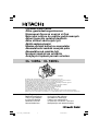 1
1
-
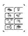 2
2
-
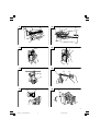 3
3
-
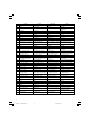 4
4
-
 5
5
-
 6
6
-
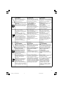 7
7
-
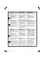 8
8
-
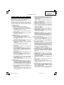 9
9
-
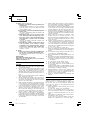 10
10
-
 11
11
-
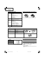 12
12
-
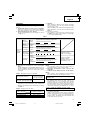 13
13
-
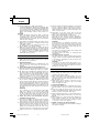 14
14
-
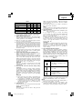 15
15
-
 16
16
-
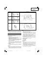 17
17
-
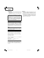 18
18
-
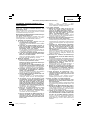 19
19
-
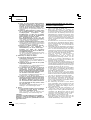 20
20
-
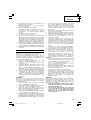 21
21
-
 22
22
-
 23
23
-
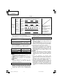 24
24
-
 25
25
-
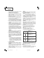 26
26
-
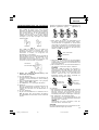 27
27
-
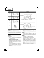 28
28
-
 29
29
-
 30
30
-
 31
31
-
 32
32
-
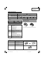 33
33
-
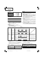 34
34
-
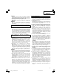 35
35
-
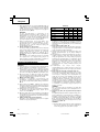 36
36
-
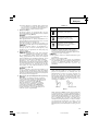 37
37
-
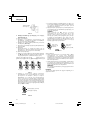 38
38
-
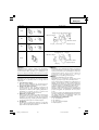 39
39
-
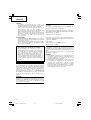 40
40
-
 41
41
-
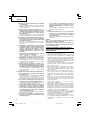 42
42
-
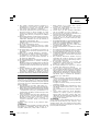 43
43
-
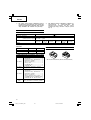 44
44
-
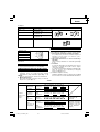 45
45
-
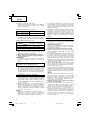 46
46
-
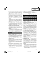 47
47
-
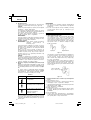 48
48
-
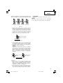 49
49
-
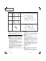 50
50
-
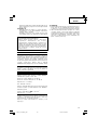 51
51
-
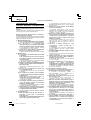 52
52
-
 53
53
-
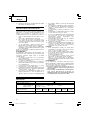 54
54
-
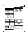 55
55
-
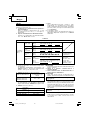 56
56
-
 57
57
-
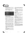 58
58
-
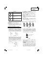 59
59
-
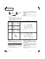 60
60
-
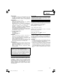 61
61
-
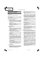 62
62
-
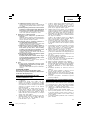 63
63
-
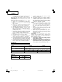 64
64
-
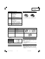 65
65
-
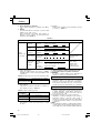 66
66
-
 67
67
-
 68
68
-
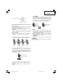 69
69
-
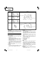 70
70
-
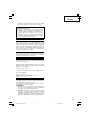 71
71
-
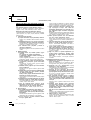 72
72
-
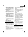 73
73
-
 74
74
-
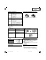 75
75
-
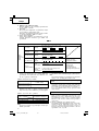 76
76
-
 77
77
-
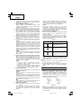 78
78
-
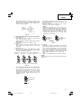 79
79
-
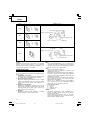 80
80
-
 81
81
-
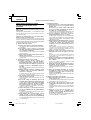 82
82
-
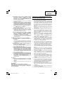 83
83
-
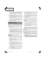 84
84
-
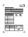 85
85
-
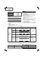 86
86
-
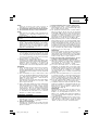 87
87
-
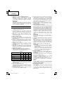 88
88
-
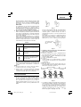 89
89
-
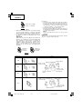 90
90
-
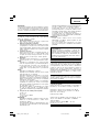 91
91
-
 92
92
-
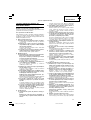 93
93
-
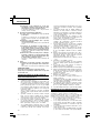 94
94
-
 95
95
-
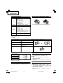 96
96
-
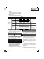 97
97
-
 98
98
-
 99
99
-
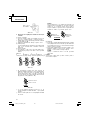 100
100
-
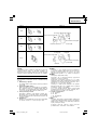 101
101
-
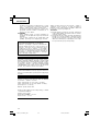 102
102
-
 103
103
-
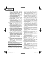 104
104
-
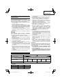 105
105
-
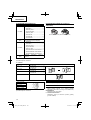 106
106
-
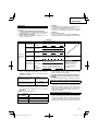 107
107
-
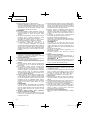 108
108
-
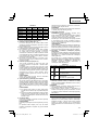 109
109
-
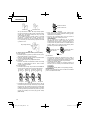 110
110
-
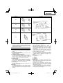 111
111
-
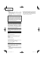 112
112
-
 113
113
-
 114
114
-
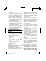 115
115
-
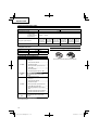 116
116
-
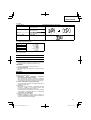 117
117
-
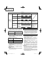 118
118
-
 119
119
-
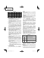 120
120
-
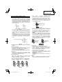 121
121
-
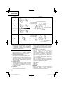 122
122
-
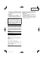 123
123
-
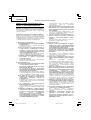 124
124
-
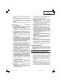 125
125
-
 126
126
-
 127
127
-
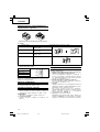 128
128
-
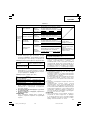 129
129
-
 130
130
-
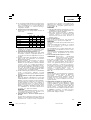 131
131
-
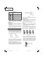 132
132
-
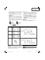 133
133
-
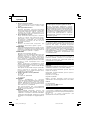 134
134
-
 135
135
-
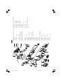 136
136
-
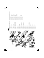 137
137
-
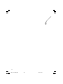 138
138
-
 139
139
-
 140
140
-
 141
141
-
 142
142
-
 143
143
-
 144
144


Hitachi CL 14DSL Handling Instructions Manual
- Kategori
- Elektrikli aletler
- Tip
- Handling Instructions Manual
- Bu kılavuz aynı zamanda aşağıdakiler için de uygundur:
diğer dillerde
- slovenčina: Hitachi CL 14DSL
- polski: Hitachi CL 14DSL
- română: Hitachi CL 14DSL
İlgili makaleler
-
Hikoki CL 14DSL Kullanım kılavuzu
-
Hikoki WH14DCL Kullanım kılavuzu
-
Hikoki WM 18DBL Kullanım kılavuzu
-
Hitachi CJ 18DSL Kullanma talimatları
-
Hitachi CH 18DSL Handling Instructions Manual
-
-
-
-
-