Yamaha RX-V1000RDS Kullanım kılavuzu
- Kategori
- AV alıcıları
- Tip
- Kullanım kılavuzu

YAMAHA ELECTRONICS CORPORATION, USA 6660 ORANGETHORPE AVE., BUENA PARK, CALIF. 90620, U.S.A.
YAMAHA CANADA MUSIC LTD. 135 MILNER AVE., SCARBOROUGH, ONTARIO M1S 3R1, CANADA
YAMAHA ELECTRONIK EUROPA G.m.b.H. SIEMENSSTR. 22-34, 25462 RELLINGEN BEI HAMBURG, F.R. OF GERMANY
YAMAHA ELECTRONIQUE FRANCE S.A. RUE AMBROISE CROIZAT BP70 CROISSY-BEAUBOURG 77312 MARNE-LA-VALLEE CEDEX02, FRANCE
YAMAHA ELECTRONICS (UK) LTD. YAMAHA HOUSE, 200 RICKMANSWORTH ROAD WATFORD, HERTS WD1 7JS, ENGLAND
YAMAHA SCANDINAVIA A.B. J A WETTERGRENS GATA 1, BOX 30053, 400 43 VÄSTRA FRÖLUNDA, SWEDEN
YAMAHA MUSIC AUSTRALIA PTY, LTD. 17-33 MARKET ST., SOUTH MELBOURNE, 3205 VIC., AUSTRALIA
Printed in Malaysia ID
V641400
RX-V1000RDS
Natural Sound AV Receiver
Ampli-tuner audio-vidéo
G B
OWNER’S MANUAL
MODE D’EMPLOI
BEDIENUNGSANLEITUNG
BRUKSANVISNING
MANUALE DI ISTRUZIONI
MANUAL DE INSTRUCCIONES
GEBRUIKSAANWIJZING
RX-V1000RDS
0100V1000RDS-cv1/4 9/11/0, 6:04 PM1

II
1 To assure the finest performance, please read this
manual carefully. Keep it in a safe place for future
reference.
2 Install this unit in a well ventilated, cool, dry, clean
place with at least 5 cm of ventilation space on the
top, right and left, and at the back of this unit
— away from direct sunlight, heat sources,
vibration, dust, moisture, and/or cold.
3 Locate this unit away from other electrical
appliances, motors, or transformers to avoid
humming sounds. To prevent fire or electrical
shock, do not place this unit where it may get
exposed to rain, water, and/or any type of liquid.
4 Do not expose this unit to sudden temperature
changes from cold to hot, and do not locate this
unit in a environment with high humidity (i.e. a
room with a humidifier) to prevent condensation
inside this unit, which may cause an electrical
shock, fire, damage to this unit, and/or personal
injury.
5 On the top of this unit, do not place:
– Other components, as they may cause damage
and/or discoloration on the surface of this unit.
– Buring objects (i.e. candles), as they may cause
fire, damage to this unit, and/or personal injury.
– Containers with liquid in them, as they may cause
electrical shock to the user and/or damage to this
unit.
6 Do not cover the rear panel of this unit with a
newspaper, tablecloth, curtain, etc. in order not to
obstruct heat radiation. If the temperature inside
this unit rises, it may cause fire, damage to this
unit, and/or personal injury.
7 Do not plug in this unit to a wall outlet until all
connections are complete.
8 Do not operate this unit upside-down. It may
overheat, possibly causing damage.
9 Do not use force on switches, knobs and/or cords.
10 When disconnecting the power cord from the wall
outlet, grasp the plug; do not pull the cord.
11 Do not clean this unit with chemical solvents; this
might damage the finish. Use a clean, dry cloth.
12 Only voltage specified on this unit must be used.
Using this unit with a higher voltage than specified
is dangerous and may cause fire, damage to this
unit, and/or personal injury. YAMAHA will not be
held responsible for any damage resulting from use
of this unit with a voltage other than specified.
13 To prevent damage by lightning, disconnect the
power cord from the wall outlet during an electrical
storm.
14 Take care of this unit so that no foreign objects and/
or liquid drops inside this unit.
CAUTION: READ THIS BEFORE OPERATING YOUR UNIT.
15 Do not attempt to modify or fix this unit. Contact
qualified YAMAHA service personnel when any
service is needed. The cabinet should never be
opened for any reasons.
16 When not planning to use this unit for long periods
of time (i.e. vacation), disconnect the AC power
plug from the wall outlet.
17 Be sure to read the “TROUBLESHOOTING” section
on common operating errors before concluding that
this unit is faulty.
18 Before moving this unit, press STANDBY/ON to set
this unit in the standby mode, and disconnect the
AC power plug from the wall outlet.
This unit is not disconnected from the AC power
source as long as it is connected to the wall outlet,
even if this unit itself is turned off. This state is called
the standby mode. In this state, this unit is designed to
consume a very small quantity of power.
■ For U.K. customers
If the socket outlets in the home are not suitable for the
plug supplied with this appliance, it should be cut off and
an appropriate 3 pin plug fitted. For details, refer to the
instructions described below.
Note
• The plug severed from the mains lead must be destroyed, as a
plug with bared flexible cord is hazardous if engaged in a live
socket outlet.
■ Special Instructions for U.K.
Model
IMPORTANT
THE WIRES IN MAINS LEAD ARE COLOURED
IN ACCORDANCE WITH THE FOLLOWING
CODE:
Blue: NEUTRAL
Brown: LIVE
As the colours of the wires in the mains lead of this
apparatus may not correspond with the coloured
markings identifying the terminals in your plug,
proceed as follows:
The wire which is coloured BLUE must be connected
to the terminal which is marked with the letter N or
coloured BLACK. The wire which is coloured
BROWN must be connected to the terminal which is
marked with the letter L or coloured RED.
Making sure that neither core is connected to the earth
terminal of the three pin plug.
CAUTION
0101V1000RDS_Cau_EN 9/5/0, 4:41 PM2

1
EnglishINTRODUCTION PREPARATION
BASIC
OPERATION
ADDITIONAL
INFORMATION
APPENDIX
ADVANCED
OPERATION
CONTENTS
INTRODUCTION
INTRODUCTION
CONTENTS........................................................... 1
FEATURES............................................................ 2
GETTING STARTED........................................... 3
Checking the Package Contents ............................... 3
Installing Batteries in the Remote Control ............... 3
CONTROLS AND FUNCTIONS ........................ 4
Front Panel ............................................................... 4
Remote Control ........................................................ 6
Using the Remote Control ........................................ 8
Front Panel Display .................................................. 9
Rear Panel .............................................................. 10
PREPARATION
SPEAKER SETUP .............................................. 11
Speakers to Be Used............................................... 11
Speaker Placement ................................................. 11
CONNECTIONS ................................................. 12
Before Connecting Components ............................ 12
Connecting Audio Components ............................. 12
Connecting Video Components .............................. 14
Connecting the Speakers ........................................ 16
Connecting to an External Amplifier ..................... 18
Connecting an External Decoder ........................... 18
IMPEDANCE SELECTOR Switch ....................... 19
Connecting the Power Supply Cords ..................... 19
ON-SCREEN DISPLAY (OSD) ......................... 20
OSD Modes ............................................................ 20
Selecting the OSD Mode........................................ 20
SPEAKER MODE SETTINGS ......................... 21
Summary of SPEAKER SET Items
1A through 1F .................................................... 21
ADJUSTING THE SPEAKER
OUTPUT LEVELS ......................................... 22
Before You Begin ................................................... 22
Using the Test Tone (TEST DOLBY SUR.) .......... 23
BASIC OPERATION
BASIC PLAYBACK ........................................... 24
Input Modes and Indications .................................. 26
Selecting a Sound Field Program ........................... 28
Normal Stereo Reproduction.................................. 29
TUNING............................................................... 30
Connecting the Antennas........................................ 30
Automatic (or Manual) Tuning .............................. 31
Presetting Stations .................................................. 32
Tuning in to a Preset Station .................................. 33
Exchanging Preset Stations .................................... 34
RECEIVING RDS STATIONS .......................... 35
Description of RDS Data ....................................... 35
Changing the RDS Mode ....................................... 35
PTY SEEK Function .............................................. 36
EON Function ........................................................ 37
BASIC RECORDING......................................... 38
ADVANCED OPERATION
SET MENU .......................................................... 39
Adjusting the Items on the SET MENU................. 39
1 SPEAKER SET (speaker mode settings)........... 40
2 LOW FRQ TEST ............................................... 43
3 L/R BALANCE
(balance of the left and right main speakers) ..... 44
4 HP TONE CTRL (headphone tone control) ....... 44
5 CENTER GEQ (center graphic equalizer)......... 44
6 INPUT RENAME .............................................. 44
7 I/O ASSIGNMENT ............................................ 44
8 INPUT MODE (initial input mode) ................... 45
9 PARAM. INI (parameter initialization) ............. 45
10DOLBY D. SET (Dolby Digital set) .................. 45
11DTS LFE LEVEL .............................................. 46
126.1/ES AUTO ..................................................... 46
13SP DELAY TIME............................................... 46
14DISPLAY SET ................................................... 47
15MEMORY GUARD ........................................... 47
ADJUSTING THE LEVEL OF THE EFFECT
SPEAKERS...................................................... 48
SLEEP TIMER.................................................... 49
Setting the Sleep Timer .......................................... 49
Canceling the Sleep Timer ..................................... 49
REMOTE CONTROL FEATURES .................. 50
Control Area ........................................................... 50
Each Component Control Area .............................. 52
Setting the Manufacturer Code .............................. 57
Programming a New Remote Control Function
(Learn Feature)................................................... 58
Using the Macro Feature ........................................ 60
Changing the Source Name
in the Display Window....................................... 62
Clearing a Learned Function or Macro .................. 62
Clearing Learned Functions, Macros,
Renamed Source Names,
and Setup Manufacturer Codes .......................... 63
ADDITIONAL INFORMATION
SOUND FIELD PROGRAM ............................. 64
Hi-Fi DSP Programs............................................... 64
CINEMA DSP Programs ........................................ 65
MOVIE THEATER Programs................................ 68
SOUND FIELD PROGRAM PARAMETER
EDITING ......................................................... 69
What is a sound field? ............................................ 69
Sound Field Program Parameters ........................... 69
Changing Parameter Settings ................................. 70
Resetting a Parameter to the Factory-set Value ...... 70
Digital Sound Field Parameter Descriptions .......... 71
APPENDIX
TROUBLESHOOTING ..................................... 75
SPECIFICATIONS ............................................. 80
0102V1000RDS_1-10_EN 9/5/0, 4:41 PM1

2
Thank you for selecting this YAMAHA AV receiver.
Built-in 5-Channel Power Amplifier
◆ Minimum RMS Output Power
(0.04% THD, 20 Hz – 20 kHz)
Main: 100 W + 100 W (8 Ω)
Center: 100 W (8 Ω)
Rear: 100 W + 100 W (8 Ω)
Multi-Mode Digital Sound Field
Processing
◆ Digital Sound Field Processor (DSP)
◆ Dolby Pro Logic decoder
◆ Dolby Digital/Dolby Digital Matrix 6.1
Decoder
◆ DTS/DTS ES Decoder
◆ CINEMA DSP: Combination of YAMAHA
DSP Technology and Dolby Pro Logic, Dolby
Digital or DTS
◆ Virtual CINEMA DSP
◆ SILENT CINEMA DSP
Sophisticated AM/FM Tuner
◆ 40-Station Random Access Preset Tuning
◆ Automatic Preset Tuning
◆ Preset Station Shifting Capability (Preset
Editing)
◆ Multi-Function for RDS Broadcast Reception
Other Features
◆ 96-kHz/24-bit D/A Converter
◆ “SET MENU” which Provides You with
15 Items for Optimizing This Unit for Your
Audio/Video System
◆ Test Tone Generator for Easier Speaker Balance
Adjustment
◆ 6-Channel External Decoder Input for Other
Future Formats
◆ BASS EXTENSION Button for Reinforcing
Bass Response
◆ On Screen Display Function Helpful in
Controlling This Unit
◆ S Video Signal Input/Output Capability
◆ Component Video Input/Output Capability
◆ Optical and Coaxial Digital Audio Signal
Jacks
◆ Sleep Timer
◆ Multi-Function Remote Control
FEATURES
Manufactured under license from Dolby Laboratories. “Dolby”,
“AC-3”, “Pro Logic”, “Surround EX” and the double-D symbol
are trademarks of Dolby Laboratories.
Confidential Unpublished Works. © 1992-1997 Dolby
Laboratories, Inc. All rights reserved.
Manufactured under license from Digital Theater Systems, Inc.
US Pat. No. 5,451,942 and other world-wide patents issued and
pending. “DTS”, “DTS Digital Surround” and “DTS ES” are
trademarks of Digital Theater Systems, Inc. Copyright 1996
Digital Theater Systems, Inc. All Rights Reserved.
• y indicates a tip for your operation.
• Some operations can be performed by using either the buttons on the main unit or on the remote control. In cases when the button
names differ between the main unit and the remote control for such operations, the button name on the remote control is given in
parentheses in this manual.
0102V1000RDS_1-10_EN 9/5/0, 4:41 PM2

3
EnglishINTRODUCTION PREPARATION
BASIC
OPERAIONT
ADDITIONAL
INFORMATION
APPENDIX
ADVANCED
OPERATION
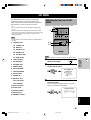
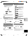
GETTING STARTED
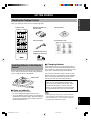
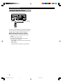
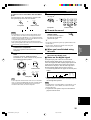
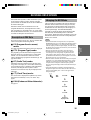
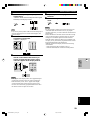
Checking the Package Contents
Check your package to make sure it has the following items.
Remote control
Manganese batteries (3)
(AA, R6, UM-3)
Indoor FM antenna
AM loop antenna
Quick Reference Card
Installing Batteries in the Remote
Control
Insert the batteries in the correct direction by aligning the
+ and – marks on the batteries with the polarity markings
(+ and –) inside the battery compartment.
RESET button
■ Notes on batteries
• Change the batteries periodically.
• Do not use old batteries together with new ones.
• Do not use different types of batteries (such as alkaline
and manganese batteries) together. Read the packaging
carefully as these different types of batteries may have
the same shape and color.
■ Changing batteries
As the batteries lose power, the operating range of the
remote control decreases and the TRANSMIT indicator
does not flash or its light becomes dim. When you notice
any of these conditions, change all of the batteries.
After you have inserted new batteries, be sure to push
RESET in the battery compartment by using a ballpoint
pen or similar object before using the remote control.
(This does not clear the contents of the memory.)
If the remote control is without batteries for more than
3 minutes, or if exhausted batteries remain in the
remote control, the contents of the memory may be
cleared. When the memory is cleared, insert new
batteries, set up the manufacturer code and program
any acquired functions that may have been cleared.
TRANSMIT RE-NAME CLEAR
MACRO
MACROLEARN
OFF ON
SYSTEM
POWER
STANDBY
PHONO
V-AUX TUNER MD/TAPE CD-R CD
D-TV/LD CBL/SAT VCR 1 VCR 2/DVR DVD
6CH INPUT
TITLE
ENTER
MENU
SOUND
DISPLAY
SOURCE
SELECT
SEARCH CHAPTER
10KEY DSP HALL 1 HALL 2 CHURCH JAZZ CLUB
ROCK
CONCERT STADIUM
TV
SPORTS
ENTER-
TAINMENT
POWER REC STOP PAUSE PLAY
6.1/ES
MONO
MOVIE
MOVIE
THEATER 2
MOVIE
THEATER 1
/DTS
SUR.
0 +10 +100
1234
5678
9101112
++ +
TV VOL
A / B / C / D / E PRESET
TV INPUT
TV MUTE
CH
DISC
MUTE
EFFECT
VOLUME
+–
/
CHP/INDEX
–– –
Note
• If the batteries have leaked, dispose of them immediately.
Avoid touching the leaked material or letting it come into
contact with clothing, etc. Clean the battery compartment
thoroughly before installing new batteries.
75-ohm/300-ohm antenna
adapter (U.K. model only)
0102V1000RDS_1-10_EN 9/5/0, 4:41 PM3

4
CONTROLS AND FUNCTIONS
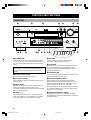
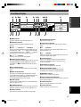
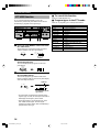
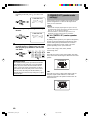
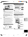
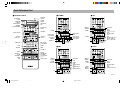
Front Panel
1 STANDBY/ON
Turns on and sets this unit in the standby mode. When
you turn on this unit, you will hear a click and there will
be a 4 to 5-second delay before this unit can reproduce
sound.
Standby mode
In this mode, this unit consumes a small amount of
power to receive infrared-signals from the remote
control.
2 Remote control sensor
Receives signals from the remote control.
3 Front panel display
Shows information about the operational status of this
unit (see page 9).
4 INPUT MODE
Selects the mode of input for sources that send two or
more types of signals to this unit (see page 26).
You cannot control the input mode when you select 6CH
INPUT as the input source.
5 INPUT l / h
Selects the input source (DVD, D-TV/LD, CBL/SAT,
VCR 1, VCR 2/DVR, V-AUX, PHONO, CD, TUNER,
CD-R, MD/TAPE) you want to listen to or watch.
6 VOLUME
Controls the output level of all audio channels.
This does not affect the REC OUT level.
7 6CH INPUT
Selects the source connected to the 6CH INPUT jacks.
The source selected by pressing 6CH INPUT takes
priority over the source selected with INPUT l / h (or
the input selector buttons).
8 SPEAKERS A/B
Turn on or off the set of main speakers connected to the A
and/or B terminals on the rear panel.
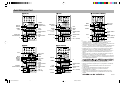
9 BASS EXTENSION ON/OFF
When pushed in (ON), this feature boosts the bass
frequency of the left and right main channels by +6 dB
(60 Hz) while maintaining overall tonal balance. This
boost is useful if you do not use a subwoofer.
However, this boost may not be noticeable if “1B MAIN
SP” on the SET MENU is set to SMALL and “1E LFE/
BASS OUT” is set to SWFR.
0 PROCESSOR DIRECT ON/OFF
When pushed in (ON), BASS, TREBLE, and BASS
EXTENSION are bypassed, eliminating any alteration of
the original signal.
VCR2
/DVR
V-AUX
VCR 1
CBL/SAT
D-TV/LD
DVD
SOURCE
REC OUT
A/B/C/D/E
SPEAKERS
STANDBY
/ON
AB
BASS
EXTENSION
PROCESSOR
DIRECT
PRESET/
TUNING
MD/TAPE
CD-R
TUNER
CD
PHONO
BASS
6CH INPUT
VOLUME
INPUT
INPUT MODE
–
+
TREBLE
–
+
PRESET
/TUNING
EDIT
MEMORY
MAN'L/AUTO FM
TUNING
MODE
AUTO/MAN'L MONO
RDS MODE
/FREQ
EON PTY SEEK
MODE
START
FM/AM
PHONES S VIDEO VIDEO
L AUDIO R OPTICAL
SILENT
VIDEO AUX
EFFECT
PROGRAM
ON OFF
SURROUND
DIGITAL
DIGITAL
123 4567
89 0
q
w
e
rt yu
hj
PRESET
/TUNING
EDIT
MEMORY
MAN'L/AUTO FM
TUNING
MODE
AUTO/MAN'L MONO
RDS MODE
/FREQ
EON PTY SEEK
MODE
START
FM/AM
i
o
pa
s
d
fg
0102V1000RDS_1-10_EN 9/5/0, 4:41 PM4

5
EnglishINTRODUCTION PREPARATION
BASIC
OPERAIONT
ADVANCED
OPERATION
ADDITIONAL
INFORMATION
APPENDIX
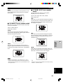
CONTROLS AND FUNCTIONS
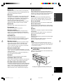
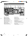
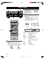
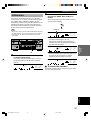
q REC OUT
Selects the source you want to direct to the audio/video
recorder outputs. When set to the SOURCE position, the
input source is directed to all outputs.
w EFFECT
Switches the effect speakers (center, rear and rear center
(see page 17)) on and off. If you turn off the output of
these speakers by using EFFECT, all Dolby Digital and
DTS audio signals except for the LFE channel are
directed to the left and right main channels.
When Dolby Digital or DTS signals are mixed, the left
and right main channel signal levels may not match.
e A/B/C/D/E
Selects one of the 5 preset station groups (A to E).
r PROGRAM l / h
Selects the DSP program (see page 28).
t PRESET/TUNING l / h
Selects preset station number 1 to 8 when the colon (:)
appears next to the band indication on the front panel
display, and selects the tuning frequency when the colon
(:) does not appear.
y PHONES jack
Outputs audio signals for private listening with
headphones. When you connect headphones, no signals
are output to the PRE OUT jacks or to the speakers.
u VIDEO AUX jacks
Inputs audio and video signals from a portable external
source such as a game console. To reproduce source
signals from these jacks, select V-AUX as the input
source. To direct this source to the VCR 1 output jacks,
select V-AUX by using REC OUT.
i PRESET/TUNING (EDIT)
Switches the function of PRESET/TUNING l / h (the
colon (:) turns on or off) between selecting a preset station
number and tuning.
This button is also used to exchange the assignment of
two preset stations with each other.
o FM/AM
Switches the reception band between FM and AM.
p MEMORY (MAN’L/AUTO FM)
Stores a station in the memory. Hold down this button for
more than 3 seconds to start automatic preset tuning.
a TUNING MODE (AUTO/MAN’L MONO)
Switches the tuning mode between automatic and manual.
To select the automatic tuning mode, press this button so
that the “AUTO” indicator lights up on the front panel
display. To select the manual tuning mode, press this
button so that the “AUTO” indicator does not light up.
DIGITAL
sRDS MODE/FREQ
When an RDS station is received, press this button to
change the display mode among the PS mode, PTY mode,
RT mode, CT mode (if the station offers those RDS data
services) and/or frequency display mode in turn.
d EON
Press this button to select the desired program type
(NEWS, INFO, AFFAIRS, SPORT) when you want to
tune in to a radio program of that type automatically.
f PTY SEEK MODE
Press this button to set the unit in the PTY SEEK mode.
g PTY SEEK START
Press this button to begin searching for a station after the
desired program type has been selected in the PTY SEEK
mode.
h BASS
Adjusts the low-frequency response for the left and right
main channels.
Turn the control to the right to increase or to the left to
decrease the low-frequency response.
j TREBLE
Adjusts the high-frequency response for the left and right
main channels.
Turn the control to the right to increase or to the left to
decrease the high-frequency response.
Note
• If you increase or decrease the high-frequency or the low-
frequency sound to an extreme level, the tonal quality from the
center, rear and rear center speakers may not match that of the
left and right main speakers.
■ Opening and closing the front
panel door
When you are not operating the controls behind the front
panel door, close the door.
To open, press gently on the lower part of the panel.
0102V1000RDS_1-10_EN 9/5/0, 4:41 PM5

6
CONTROLS AND FUNCTIONS
A Programming section
Provides a selection of programming types you can utilize to
conveniently operates your other components.
B A and B buttons
See page 50.
C Operation section
Provides functions such as play, stop, skip, etc. for operating
your other components.
D Others
Functions vary depending on your components that are set up
with the manufacturer code.
E Setup section
Sets speaker output levels, SET MENU, DSP parameters, etc.
Remote Control
This section describes the basic operation of this unit with the remote control. See “REMOTE CONTROL FEATURES”
on pages 50 to 63 for full details.
ON SCREEN
LEVEL
SLEEP TEST
PARAMETER
SET MENU
TRANSMIT RE-NAME CLEAR
MACRO
MACROLEARN
OFF ON
SYSTEM
POWER
STANDBY
PHONO
V-AUX TUNER MD/TAPE CD-R CD
D-TV/LD CBL/SAT VCR 1 VCR 2/DVR DVD
6CH INPUT
TITLE
ENTER
MENU
SOUND
DISPLAY
SOURCE
SELECT
SEARCH CHAPTER
10KEY DSP HALL 1 HALL 2 CHURCH JAZZ CLUB
ROCK
CONCERT STADIUM
TV
SPORTS
ENTER-
TAINMENT
POWER REC STOP PAUSE PLAY
6.1/ES
MONO
MOVIE
MOVIE
THEATER 2
MOVIE
THEATER 1
/DTS
SUR.
0 +10 +100
1234
5678
9101112
++ +
TV VOL
A / B / C / D / E PRESET
TV INPUT
TV MUTE
CH
DISC
MUTE
EFFECT
VOLUME
+–
/
CHP/INDEX
–– –
e
t
r
y
u
i
o
p
a
s
l
j
k
d
w
q
0
9
8
7
6
4
5
3
2
1
f
g
h
A
B
C
D
E
0102V1000RDS_1-10_EN 9/5/0, 4:41 PM6

7
EnglishINTRODUCTION PREPARATION
BASIC
OPERAIONT
ADVANCED
OPERATION
ADDITIONAL
INFORMATION
APPENDIX
CONTROLS AND FUNCTIONS
1 Infrared window
Outputs infrared control signals. Aim this window at the
component you want to operate.
2 TRANSMIT indicator
Flashes while the remote control is sending signals.
3 STANDBY
Sets this unit in the standby mode.
4 SYSTEM POWER
Turns on the power of this unit.
5 Input selector buttons
Select the input source.
6 Display window
Shows the selected source component that you are
controlling.
7 SOURCE SELECT k/n
Selects the source component without switching the
input.
8 10KEY/DSP
Selects the numeric button (10KEY) mode or DSP mode.
9 DSP program group/Numeric buttons
Select DSP programs or numbers according to the
position of 10KEY/DSP. (Press a button repeatedly to
select a DSP program within that group.)
0 6.1/ES
Turns on or off the Dolby Digital Matrix 6.1 or DTS ES
decoder with 10KEY/DSP set to the DSP position.
q A/B/C/D/E
Selects one of the 5 preset station groups.
w PRESET +/–
Selects a preset station number (1 to 8).
e RE-NAME
Used for changing the input source name in the display
window (see page 62).
r CLEAR
Used for clearing functions acquired when using the learn
and rename features, programmed macros, and set
manufacturer codes (see pages 62 and 63).
t LEARN
Used for setting up the manufacturer code or for
programming the functions of other remote controls (see
pages 57 to 59).
y MACRO
Used to program a series of operations for control by a
single button (see page 61).
u MACRO ON/OFF
Turns the macro function on and off.
i 6CH INPUT
Selects the source connected to the 6CH INPUT jacks.
o MUTE
Mutes the sound. Press again to restore the audio output
to the previous volume level.
p VOLUME +/–
Increases or decreases the volume level.
a EFFECT
Switches the effect speakers (center, rear and rear center
(see page 17)) on and off. If the output of these speakers
is turned off, all Dolby Digital and DTS audio signals
except for the LFE channel are directed to the left and
right main channels.
s Cover
Slides down to show the setup buttons.
d LEVEL
Selects the effect speaker channels (center, rear, rear
center (see page 17) and subwoofer) so you can adjust
their output level independently.
f ON SCREEN
Selects the on-screen display (OSD) mode for your video
monitor.
g SLEEP
Sets the sleep timer.
h TEST
Outputs the test tone.
j PARAMETER/SET MENU
Selects the PARAMETER mode or SET MENU mode.
k Cursor buttons k/n/–/+
Select and adjust DSP program parameters and SET
MENU items according to the position of PARAMETER/
SET MENU.
l RESET
Press this button after you have changed the batteries or
when the remote control stops working properly.
(Pressing RESET does not clear the acquired functions.)
0102V1000RDS_1-10_EN 9/5/0, 4:41 PM7

8
CONTROLS AND FUNCTIONS
Using the Remote Control
The remote control transmits a directional infrared beam.
Be sure to aim the remote control directly at the remote
control sensor on the main unit during operation.
■ Handling the remote control
• Do not spill water or other liquids on the remote
control.
• Do not drop the remote control.
• Do not leave or store the remote control in the
following types of conditions:
– high humidity or temperature such as near a heater,
stove or bath;
– dusty places; or
– in places subject to extremely low temperatures.
STANDBY
/ON
–
+
–
+
SURROUND
DIGITAL
DIGITAL
30° 30°
0
1234
5678
9101112
++ +
+–
/
–– –
Approximately 6 m (20 feet)
0102V1000RDS_1-10_EN 9/5/0, 4:41 PM8

9
EnglishINTRODUCTION PREPARATION
BASIC
OPERAIONT
ADVANCED
OPERATION
ADDITIONAL
INFORMATION
APPENDIX
CONTROLS AND FUNCTIONS
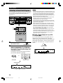
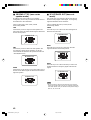
Front Panel Display
1 t indicator
Lights up when the built-in DTS decoder is on.
2 VIRTUAL indicator
Lights up when using Virtual CINEMA DSP (see
page 29).
3 g and o indicators
Light up according to the type of Dolby signals this unit
is reproducing. “ g ” lights up when the built-
in Dolby Digital decoder is on. “ o ” lights up
when the built-in Dolby Pro Logic decoder is on.
4 x indicator
Lights up when you select a DSP program.
5 DSP program indicators
The name of the selected DSP program lights up when the
ENTERTAINMENT, MOVIE THEATER 1, MOVIE
THEATER 2 or q/DTS SURROUND DSP program is
selected.
6 PTY HOLD indicator
Lights up while searching for stations in the PTY SEEK
mode.
7 RDS mode indicators
The name(s) of the RDS data offered by the currently
received RDS station light(s) up. Illumination of the red
indicator next to the RDS data name shows that the
corresponding RDS mode is now selected.
8 EON indicator
Lights up when an RDS station that offers the EON data
service is being received.
9 STEREO indicator
Lights up when the unit is receiving a strong signal for an
FM stereo broadcast while the “AUTO” indicator is lit.
0 AUTO indicator
Shows that this unit is in the automatic tuning mode.
q VOLUME level indicator
Indicates the volume level.
w Input source indicator
Shows the current input source with the arrow-shaped
cursor.
e c indicator
Lights up when the built-in Dolby Digital Matrix 6.1 or
DTS ES decoder is on.
r v indicator
Lights up when this unit is reproducing PCM (pulse code
modulation) digital audio signals.
t SP A/B indicator
Lights up according to which set of main speakers is
selected. Both indicators light up when both sets of
speakers are selected.
y Headphones indicator
Lights up when headphones are connected.
u Multi-information display
Shows the current DSP program name and other
information when adjusting or changing settings.
i MEMORY indicator
Flashes to show a station can be stored.
o Program type name indicators
The name of the selected program type lights up when the
“EON” indicator lights up.
p TUNED indicator
Lights up when this unit tunes in to a station.
a SLEEP indicator
Lights up while the sleep timer is on.
DIGITAL
DTS MOVIE THEATER 1
2
DOLBY DIGITAL
PRO LOGIC ENTERTAINMENT
DSP
6.1/ES
PCM
PRO LOGIC
A
SP
B
D-TV/LD
CBL/SAT
VCR 1
VCR2/DVR
V-AUX
DVD
MD/TAPE
CD-R
TUNER
CD
PHONO
VIRTUAL
PS
PTY
RT
CT
PTY
HOLD
EON
STEREO
AUTO
NEWS INFO AFFAIRS SPORT
MEMORY TUNED
VOLUME
dB
ms
SLEEP
1 234 wq87
apio
6
uyre t
09 5
0102V1000RDS_1-10_EN 9/5/0, 4:41 PM9

10
CONTROLS AND FUNCTIONS
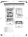
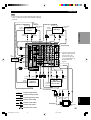
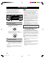
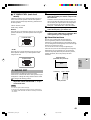
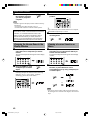
Rear Panel
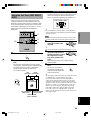
1 DIGITAL INPUT jacks
2 DIGITAL OUTPUT jacks
3 Antenna input terminals
See page 30 for connection information.
4 Audio component jacks
See pages 12 and 13 for connection information.
5 Video component jacks
See pages 14 and 15 for connection information.
6 Speaker terminals
See pages 16 and 17 for connection information.
7 PRE OUT/MAIN IN jacks
See page 18 for connection information.
DIGITAL OUTPUT AUDIO AUDIO VIDEO
SPEAKERS
MAIN
CENTER
REAR
(SURROUND)
TUNER
DIGITAL INPUT 6CH INPUT
MD/
TAPE
CD-R
CD-R
CD
DVD
FM
ANT
AM
ANT
GND
GND
75
UNBAL.
D-TV
/LD
OPTICAL
OPTICAL
COAXIAL
CD
IN
(PLAY)
DVD
S VIDEO VIDEO COMPONENT
DVD
Y
P
B
/
C
B
P
R
/
C
R
S VIDEO VIDEO
D-TV
/LD
CBL
/SAT
IN
VCR 1
OUT
IN
VCR 2
/DVR
OUT
MONITOR
OUT
R
MD/TAPE
CBL
/SAT
OUT
(REC)
CD
PHONO
MAIN
CENTER
SUB
WOOFER
SURROUND
IN
(PLAY)
CD-R
OUT
(REC)
L R L
CENTER
SUB
WOOFER
LR
R
+
–
L
R L
D-TV/LD
A
Y
P
B
/
C
B
P
R
/
C
R
MONITOR
OUT
Y
P
B
/
C
B
P
R
/
C
R
+
–
–
+
+
– –
+
B
REAR
(SURROUND)
MAIN A OR B: 4
MIN. /SPEAKER
A
+
B: 8
MIN. /SPEAKER
CENTER
: 6
MIN. /SPEAKER
REAR
: 6
MIN. /SPEAKER
MAIN A OR B: 8
MIN. /SPEAKER
A
+
B:
16
MIN. /SPEAKER
CENTER
: 8
MIN. /SPEAKER
REAR
: 8
MIN. /SPEAKER
IMPEDANCE SELECTOR
SET BEFORE POWER ON
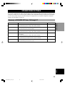
SWITCHED
100W MAX. TOTAL
AC OUTLETS
RS-
232C
PRE OUT/MAIN IN
REAR
CENTER
R L
MAINS
MAIN
IN
MAIN
OUT
5
8
wq09
7
64321
(Europe model)
8 AC power cord
Connect to a power outlet.
9 RS-232C connector
This is a control expansion connector for commercial use.
Consult your dealer for details.
0 6CH INPUT jacks
See pages 13 and 18 for connection information.
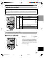
q IMPEDANCE SELECTOR switch
Use this switch to match the amplifier output to your
speaker impedance. Set this unit in the standby mode
before you change the setting of this switch (see page 19).
w AC OUTLET(S)
Use these outlets to supply power to your other A/V
components (see page 19).
0102V1000RDS_1-10_EN 9/5/0, 4:41 PM10

11
EnglishINTRODUCTION PREPARATION
BASIC OPERA-
TION
ADVANCED
OPERATION
ADDITIONAL
INFORMATION
APPENDIX
SPEAKER SETUP
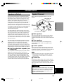
Speakers to Be Used
This unit has been designed to provide the best sound-
field quality with a 5-speaker system, using left and right
main speakers, left and right rear speakers and a center
speaker. The 6-speaker system, which adds a rear center
speaker to the 5 speaker configuration, is the latest
advancement in surround sound technology. (See page 17
for using the rear center speaker.) If you use different
brands of speakers (with different tonal qualities) in your
system, the tone of a moving human voice and other types
of sound may not shift smoothly. We recommend that you
use speakers from the same manufacturer or speakers
with the same tonal quality.
The main speakers are used for the main source sound
plus the effect sounds. They will probably be the speakers
from your present stereo system. The rear speakers are
used for the effect and surround sounds, and the center
speaker is for the center sounds (dialog, vocals, etc.). If
for some reason it is not practical to use a center speaker,
you can do without it. Best results, however, are obtained
with the full system.
The main speakers should be high-performance models
and have enough power-handling capacity to accept the
maximum output of your audio system. The other
speakers do not have to be equal to the main speakers.
For precise sound localization, however, it is ideal to use
high-performance models that can reproduce sounds over
the full range for the center speaker and the rear speakers.
■ Use of a subwoofer expands your
sound field
It is also possible to further expand your system with the
addition of a subwoofer. The use of a subwoofer is
effective not only for reinforcing bass frequencies from
any or all channels, but also for reproducing the LFE
(low-frequency effect) channel with high fidelity when
the Dolby Digital signal or the DTS signal is played back.
The YAMAHA Active Servo Processing Subwoofer
System is ideal for natural and lively bass reproduction.
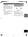
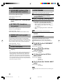
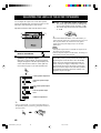
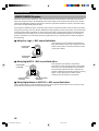
Speaker Placement
Refer to the following diagram when you place the
speakers.
Main
speaker (L)
Center speaker
Main speaker (R)
Subwoofer
Rear speaker (R)
Rear center
speaker
See page 17.
Rear speaker (L)
■ Main speakers
Place the left and right main speakers an equal distance
from the ideal listening position. The distance of each
speaker from each side of the video monitor should be the
same.
■ Rear speakers
Place these speakers behind your listening position,
facing slightly inwards, nearly 1.8 m (approx. 6 feet)
above the floor.
■ Center speaker
Align the front face of the center speaker with the front
face of your video monitor. Place the speaker as close to
the monitor as possible, such as directly over or under the
monitor and centrally between the main speakers.
Note
• If the center speaker is not used, the center channel sound will
be heard from the left and right main speakers. In this case,
“1A CENTER SP” on the SET MENU is set to NONE (see
page 41 for details).
■ Subwoofer
The position of the subwoofer is not so critical, because
low bass sounds are not highly directional. But it is better
to place the subwoofer near the main speakers. Turn it
slightly toward the center of the room to reduce the wall
reflections.
CAUTION
Some types of speakers interfere with a video monitor.
If this problem occurs, move the speakers away from
the monitor. If you cannot avoid installing the center
speaker or subwoofer near the video monitor, use a
magnetically shielded speaker.
PREPARATION
1.8 m
0103V1000RDS_11-18_EN 9/5/0, 4:41 PM11

12
CONNECTIONS
Before Connecting Components
CAUTION
Never connect this unit and other components to mains power until all connections between components have been
completed.
• Be sure all connections are made correctly, that is to say L (left) to L, R (right) to R, “+” to “+” and “–” to “–”. Some
components require different connection methods and have different jack names. Refer to the operation instructions
for each component to be connected to this unit.
• When you connect other YAMAHA audio components (such as a tape deck, MD recorder and CD player or
changer), connect them to the jack with the same number labels as !, #, $ etc. YAMAHA applies this labeling
system to all its products.
• After you have completed all connections, check them again to make sure they are correct.
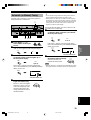
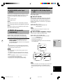
Connecting Audio Components
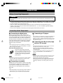
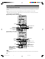
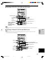
■ Connecting to digital jacks
This unit has digital jacks for direct transmission of
digital signals through either coaxial or fiber optic cables.
You can use the digital jacks to input PCM, Dolby Digital
and DTS bitstreams. When you connect components to
both the COAXIAL and OPTICAL jacks, priority is given
to the input signals from the COAXIAL jack. All digital
input jacks are acceptable for 96-kHz sampling digital
signals (see page 25 for details).
y
• You can designate the input for each digital jack according to
your component by using “7 I/O ASSIGNMENT” on the SET
MENU (see page 44 for details).
About the dust protection cap
Pull out the cap from the optical jack
before you connect the fiber optic cable.
Do not discard the cap. When you are not
using the optical jack, be sure to put the
cap back in place. This cap protects the
jack from dust.
Note
• The OPTICAL jacks on this unit conform to the EIA standard.
If you use a fiber optic cable that does not conform to this
standard, this unit may not function properly.
■ Connecting a turntable
PHONO jacks are for connecting a turntable with an MM
or high-output MC cartridge. If you have a turntable with
a low-output MC cartridge, use an inline boosting
transformer or MC-head amplifier when connecting to
these jacks.
y
• The GND terminal does not electrically ground the turntable. It
simply reduces noise in the signal. In some cases, you may
hear less noise if you do not connect to the GND terminal.
■ Connecting a CD player
y
• The COAXIAL CD and OPTICAL CD jacks are available for a
CD player which has coaxial or optical digital output jacks.
• When you connect a CD player to both the COAXIAL CD and
OPTICAL CD jacks, priority is given to the input signals from
the COAXIAL CD jack.
■ Connecting an MD recorder, tape
deck or CD recorder
y
• Only digital signals input from a source such as a CD or DVD
are output from the DIGITAL OUTPUT jacks.
• When you connect your recording component to both the
analog and digital input and output jacks, the priority is given
to the digital signal.
• You can connect an MD recorder to any digital input jack by
using “7 I/O ASSIGNMENT” on the SET MENU (see
page 44).
Notes
• When you connect a recording component to this unit, keep its
power on while using this unit. If the power is off, this unit
may distort the sound from other components.
• When you record from a source component connected to this
unit while this unit is set in the standby mode, the recorded
sound may be distorted. To avoid this problem, turn on this
unit.
0103V1000RDS_11-18_EN 9/5/0, 4:41 PM12

13
EnglishINTRODUCTION PREPARATION
BASIC OPERA-
TION
ADVANCED
OPERATION
ADDITIONAL
INFORMATION
APPENDIX
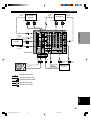
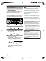
CONNECTIONS
DIGITAL OUTPUT AUDIO AUDIO VIDEO
TUNER
DIGITAL INPUT 6CH INPUT
CD-R
CD-R
DVD
FM
ANT
AM
ANT
GND
GND
75
UNBAL.
D-TV
/LD
OPTICAL
OPTICAL
COAXIAL
CD
IN
(PLAY)
DVD
S VIDEO VIDEO COMPONENT
DVD
Y
P
B
/
C
B
P
R
/
C
R
S VIDEO VIDEO
D-TV
/LD
CBL
/SAT
IN
VCR 1
OUT
IN
VCR 2
/DVR
OUT
MONITOR
OUT
R
MD/TAPE
CBL
/SAT
OUT
(REC)
CD
PHONO
MAIN
CENTER
SUB
WOOFER
SURROUND
IN
(PLAY)
CD-R
OUT
(REC)
L R L
D-TV/LD
Y
P
B
/
C
B
P
R
/
C
R
MONITOR
OUT
Y
P
B
/
C
B
P
R
/
C
R
RS-
232C
MD/
TAPE
CD
L
R
C
O
L
R
L
R
O
O
O
OUTPUT
GND
L
R
L R
L R
INPUT OUTPUT INPUTOUTPUT
OUTPUT
O
C
COAXIAL
OUTPUT
L
R
L
R
OPTICAL
OUTPUT
OPTICAL
INPUT
OPTICAL
INPUT
OPTICAL
OUTPUT
SUBWOOFER
OUTPUT
CENTER OUTPUT
MAIN
OUTPUT
SURROUND
OUTPUT
L R
indicates signal direction
indicates left analog cables
indicates right analog cables
indicates optical cables
indicates coaxial cables
MD recorder or
tape deck
CD recorder
CD player
Turntable
External decoder
See page 18.
(Europe model)
0103V1000RDS_11-18_EN 9/5/0, 4:41 PM13

14
CONNECTIONS
y
• Each type of video jack works independently. Signals input
through the composite video, S-video and component jacks are
output through the corresponding composite video, S-video, and
component jacks, respectively.
• If you make S-video connections to this unit, it is not necessary
to make composite video connections. If both types of
connections are made, this unit gives priority to the S-video
signal.
• You can designate the input for the COMPONENT VIDEO A
and B jacks according to your component by using “7 I/O
ASSIGNMENT” on the SET MENU (see page 44 for details).
Notes
• Use a commercially available S-video cable when connecting to the S VIDEO jack, and commercially available video cables when
connecting to the COMPONENT VIDEO jacks.
• When you are using the COMPONENT VIDEO jacks, check the details in the owner’s manual that came with the component being
connected.
■ Video monitor with a 21-pin connector
Make a connection as shown on page 15 with a commercially available SCART-plug connector cable.
■ VIDEO AUX jacks (on the front panel)
Y
P
B
/
C
B
P
R
/
C
R
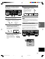
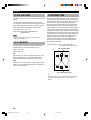
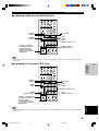
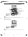
Connecting Video Components
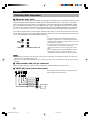
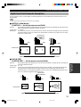
■ About the video jacks
There are three types of video jacks. Video signals input through the VIDEO jacks are the conventional composite video
signals. Video signals input through the S VIDEO jacks are separated into luminance (Y) and color (C) video signals.
The S-video signals achieve high-quality color reproduction. Video signals input through the COMPONENT VIDEO
jacks are separated into luminance (Y) and color difference (P
B
/C
B
, P
R
/C
R
) video signals. The jacks are also separated
into three for each signal. The description of the component video jacks may be different depending on the component
(e.g. Y, C
B
, C
R
/Y, P
B
, P
R
/Y, B-Y, R-Y etc.). Component video signals provide the best quality in picture reproduction.
If your video component has an S-video output or component video output, you can connect it to this unit. Connect the
S-video signal output jack on your video component to the S VIDEO jack or connect the component signal output jacks
on your video component to the COMPONENT VIDEO jacks.
VIDEO jack
(composite)
S VIDEO jack COMPONENT VIDEO jacks
Game console
S VIDEO VIDEO
L AUDIO R OPTICAL
VIDEO AUX
AUDIO OUT R
AUDIO OUT L
VIDEO OUT
OPTICAL OUT
S VIDEO OUT
O
V
L
R
S
These jacks are used to connect any video input source
such as a game console to this unit.
0103V1000RDS_11-18_EN 9/5/0, 4:41 PM14

15
EnglishINTRODUCTION PREPARATION
BASIC OPERA-
TION
ADVANCED
OPERATION
ADDITIONAL
INFORMATION
APPENDIX
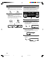
CONNECTIONS
DIGITAL OUTPUT AUDIO AUDIO VIDEO
TUNER
DIGITAL INPUT 6CH INPUT
MD/
TAPE
CD-R
CD-R
CD
DVD
FM
ANT
AM
ANT
GND
GND
75
UNBAL.
D-TV
/LD
OPTICAL
OPTICAL
COAXIAL
CD
IN
(PLAY)
DVD
S VIDEO VIDEO COMPONENT
DVD
Y
P
B/
C
B
PR/
C
R
S VIDEO VIDEO
D-TV
/LD
CBL
/SAT
IN
VCR 1
OUT
IN
VCR 2
/DVR
OUT
MONITOR
OUT
R
MD/TAPE
CBL
/SAT
OUT
(REC)
CD
PHONO
MAIN
CENTER
SUB
WOOFER
SURROUND
IN
(PLAY)
CD-R
OUT
(REC)
L R L
D-TV/LD
Y
P
B/
C
B
PR/
C
R
MONITOR
OUT
Y
P
B/
C
B
PR/
C
R
RS-
232C
C
L
R
S VIDEO
OUTPUT
S VIDEO
OUTPUT
S VIDEO
OUTPUT
S VIDEO
INPUT
VIDEO
INPUT
S VIDEO
OUTPUT
*1
AUDIO
OUTPUT
AUDIO
OUTPUT
AUDIO INPUT
AUDIO OUTPUT
COAXIAL
OUTPUT
OPTICAL
OUTPUT
RF
OUTPUT
OPTICAL
OUTPUT
VIDEO
OUTPUT
VIDEO
OUTPUT
AUDIO
OUTPUT
VIDEO
OUTPUT
S VIDEO
INPUT
VIDEO
OUTPUT
VIDEO
INPUT
RF
INPUT
O
V
S
O
L
R
L
R
L
R
L
R
V
S
COMPONENT
INPUT
COMPONENT
OUTPUT
COMPONENT
OUTPUT
V
S
V
V
S S
L
R
C
C
VV
S
L
S
R
V
O
TV/digital TV or
LD player
DVD player
Cable TV or
satellite tuner
Note
• If your LD player has a Dolby Digital RF signal output jack,
connect it to this unit through an RF demodulator (separately
purchased).
VCR 1 or
VCR 2/DVR (digital
video recorder)
Video monitor
indicates signal direction
(Europe model)
LD player
RF
demodulator
indicates left analog cables
indicates right analog cables
indicates optical cables
indicates coaxial cables
indicates video cables
indicates S-video cables
No connection
SCART-plug
*1 You can connect the Dolby
Digital RF signal output of
your LD player to the
COAXIAL jack by using
“7 I/O ASSIGNMENT” on
the SET MENU (see
page 44).
0103V1000RDS_11-18_EN 9/5/0, 4:41 PM15

16
CONNECTIONS
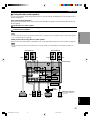
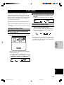
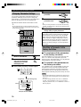
Connecting the Speakers
Be sure to connect the left channel (L), right channel (R), “+” (red) and “–” (black) properly. If the connections are
faulty, no sound will be heard from the speakers, and if the polarity of the speaker connections is incorrect, the sound
will be unnatural and lack bass.
CAUTION
• Use speakers with the specified impedance shown on the rear panel of this unit.
• Do not let the bare speaker wires touch each other and do not let them touch any metal part of this unit. This could
damage the unit and/or speakers.
If necessary, use the SET MENU to change the speaker mode settings according to the number and size of the speakers
in your configuration after you finish connecting your speakers.
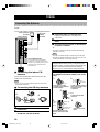
■ Speaker cables
A speaker cord is actually a pair of insulated cables
running side by side. One of the cables is colored or
shaped differently, perhaps with a stripe, groove or ridge.
1 Remove approx. 10 mm (3/8”) of insulation
from each of the speaker cables.
2 Twist the exposed wires of the cable together
to prevent short circuits.
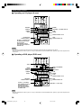
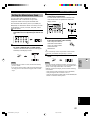
■ Connecting to the SPEAKERS terminals
1 Unscrew the knob.
2 Insert one bare wire into the hole in the side
of each terminal.
3 Tighten the knob to secure the wire.
2
1
3
12
10 mm (3/8”)
Red: positive (+)
Black: negative (–)
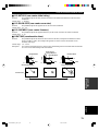
■ MAIN SPEAKERS terminals
One or two speaker systems can be connected to these terminals. If you use only one speaker system, connect it to either
of the MAIN A or B terminals.
■ REAR SPEAKERS terminals
A rear speaker system can be connected to these terminals.
■ CENTER SPEAKER terminals
A center speaker can be connected to these terminals.
0103V1000RDS_11-18_EN 9/5/0, 4:41 PM16

17
EnglishINTRODUCTION PREPARATION
BASIC OPERA-
TION
ADVANCED
OPERATION
ADDITIONAL
INFORMATION
APPENDIX
CONNECTIONS
SPEAKERS
MAIN
CENTER
REAR
(SURROUND)
CENTER
SUB
WOOFER
LR
R
+
–
L
R L
A
+
–
–
+
+
– –
+
B
REAR
(SURROUND)
MAIN A OR B: 4
MIN. /SPEAKER
A
+
B: 8
MIN. /SPEAKER
CENTER
: 6
MIN. /SPEAKER
REAR
: 6
MIN. /SPEAKER
MAIN A OR B: 8
MIN. /SPEAKER
A
+
B:
16
MIN. /SPEAKER
CENTER
: 8
MIN. /SPEAKER
REAR
: 8
MIN. /SPEAKER
IMPEDANCE SELECTOR
SET BEFORE POWER ON
SWITCHED
100W MAX. TOTAL
AC OUTLETS
PRE OUT/MAIN IN
REAR
CENTER
R L
MAINS
MAIN
IN
MAIN
OUT
Main speakers A
Right Left
Main speakers B
Right Left
(Europe model)
Center speaker Subwoofer
system
Subwoofer connection
See “SUBWOOFER jack”
on page 18.
Rear speakers
Right Left
Rear center
speaker
Power
amplifier
■ Using the rear center speaker
You can enjoy the Dolby Digital Surround EX software or DTS ES software by adding the rear center speaker to the 5-
speaker configuration.
Rear center speaker placement
Place the rear center speaker in the center between the left and right rear speakers at the same height from the floor as
the rear speakers.
Connecting the rear center speaker
1 Connect the PRE OUT REAR CENTER jack on this unit to the input jack on the separately
prepared power amplifier.
2 Connect the rear center speaker to the speaker terminals on this power amplifier.
Note
• Be sure to correctly connect the + terminal of the speaker to the + terminal on the power amplifier, and the – terminal of the speaker
to the – terminal on the power amplifier.
Setting up this unit for using the rear center speaker
When you use a rear center speaker, “1D REAR CT SP” on the SET MENU must be set to LRG or SML (see page 42).
Note
• No sound is output from the rear center speaker when “1C REAR L/R SP” on the SET MENU is set to NONE (see page 41 for
details).
0103V1000RDS_11-18_EN 9/5/0, 4:41 PM17

18
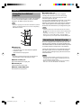
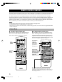
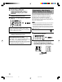
CONNECTIONS
Connecting to an External
Amplifier
If you want to increase the power output to the speakers,
or want to use another amplifier, connect an external
amplifier to the PRE OUT jacks as follows.
Note
• When RCA pin plugs are connected to the PRE OUT jacks for
output to an external amplifier, do not use the corresponding
SPEAKERS terminals.
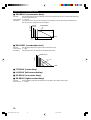
1 MAIN jacks
• MAIN IN jacks
Line input to this unit’s main channel amplifiers.
• MAIN OUT jack
Main channel line output jacks.
Note
• The signals output through these jacks are affected by the
BASS, TREBLE and BASS EXTENSION settings.
2 REAR CENTER jack
Rear center channel line output jack.
3 CENTER jack
Center channel line output jack.
4 REAR (SURROUND) jacks
Rear channel line output jacks.
PRE OUT/MAIN IN
MAIN
IN
MAIN
OUT
REAR
CENTER
CENTER
SUB
WOOFER
R L
LR
REAR
(SURROUND)
1
5
2
3
4
5 SUBWOOFER jack
When using a subwoofer with built-in amplifier,
including the YAMAHA Active Servo Processing
Subwoofer System, connect the input jack of the
subwoofer system to this jack.
Low bass signals distributed from the main, center and/or
rear channels are directed to this jack. (The cut-off
frequency of this jack is 90 Hz.) The LFE (low-frequency
effect) signals generated when Dolby Digital or DTS is
decoded are also directed if they are assigned to this jack.
Notes
• Adjust the volume level of the subwoofer with the control on
the subwoofer. The subwoofer volume cannot be adjusted from
this unit.
• Depending on the settings of “1 SPEAKER SET”, “10A LFE
LEVEL” and “11 DTS LFE LEVEL” on the SET MENU,
some signals may not be output from the SUBWOOFER jack.
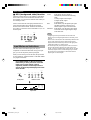
Connecting an External Decoder
This unit is equipped with 6 additional input jacks (left
and right MAIN, CENTER, left and right SURROUND
and SUBWOOFER) for discrete multi-channel input from
an external decoder, sound processor or pre-amplifier.
Connect the output jacks on your external decoder to the
6CH INPUT jacks. Be sure to match the left and right
outputs to the left and right input jacks for the main and
surround channels.
Notes
• When you select 6CH INPUT as the input source, this unit
automatically turns off the digital sound field processor, and
you cannot listen to DSP programs.
• When you select 6CH INPUT as the input source, changing
items 1A to 1F on the SET MENU is not affected.
0103V1000RDS_11-18_EN 9/5/0, 4:41 PM18
Sayfa yükleniyor...
Sayfa yükleniyor...
Sayfa yükleniyor...
Sayfa yükleniyor...
Sayfa yükleniyor...
Sayfa yükleniyor...
Sayfa yükleniyor...
Sayfa yükleniyor...
Sayfa yükleniyor...
Sayfa yükleniyor...
Sayfa yükleniyor...
Sayfa yükleniyor...
Sayfa yükleniyor...
Sayfa yükleniyor...
Sayfa yükleniyor...
Sayfa yükleniyor...
Sayfa yükleniyor...
Sayfa yükleniyor...
Sayfa yükleniyor...
Sayfa yükleniyor...
Sayfa yükleniyor...
Sayfa yükleniyor...
Sayfa yükleniyor...
Sayfa yükleniyor...
Sayfa yükleniyor...
Sayfa yükleniyor...
Sayfa yükleniyor...
Sayfa yükleniyor...
Sayfa yükleniyor...
Sayfa yükleniyor...
Sayfa yükleniyor...
Sayfa yükleniyor...
Sayfa yükleniyor...
Sayfa yükleniyor...
Sayfa yükleniyor...
Sayfa yükleniyor...
Sayfa yükleniyor...
Sayfa yükleniyor...
Sayfa yükleniyor...
Sayfa yükleniyor...
Sayfa yükleniyor...
Sayfa yükleniyor...
Sayfa yükleniyor...
Sayfa yükleniyor...
Sayfa yükleniyor...
Sayfa yükleniyor...
Sayfa yükleniyor...
Sayfa yükleniyor...
Sayfa yükleniyor...
Sayfa yükleniyor...
Sayfa yükleniyor...
Sayfa yükleniyor...
Sayfa yükleniyor...
Sayfa yükleniyor...
Sayfa yükleniyor...
Sayfa yükleniyor...
Sayfa yükleniyor...
Sayfa yükleniyor...
Sayfa yükleniyor...
Sayfa yükleniyor...
Sayfa yükleniyor...
Sayfa yükleniyor...
Sayfa yükleniyor...
Sayfa yükleniyor...
Sayfa yükleniyor...
-
 1
1
-
 2
2
-
 3
3
-
 4
4
-
 5
5
-
 6
6
-
 7
7
-
 8
8
-
 9
9
-
 10
10
-
 11
11
-
 12
12
-
 13
13
-
 14
14
-
 15
15
-
 16
16
-
 17
17
-
 18
18
-
 19
19
-
 20
20
-
 21
21
-
 22
22
-
 23
23
-
 24
24
-
 25
25
-
 26
26
-
 27
27
-
 28
28
-
 29
29
-
 30
30
-
 31
31
-
 32
32
-
 33
33
-
 34
34
-
 35
35
-
 36
36
-
 37
37
-
 38
38
-
 39
39
-
 40
40
-
 41
41
-
 42
42
-
 43
43
-
 44
44
-
 45
45
-
 46
46
-
 47
47
-
 48
48
-
 49
49
-
 50
50
-
 51
51
-
 52
52
-
 53
53
-
 54
54
-
 55
55
-
 56
56
-
 57
57
-
 58
58
-
 59
59
-
 60
60
-
 61
61
-
 62
62
-
 63
63
-
 64
64
-
 65
65
-
 66
66
-
 67
67
-
 68
68
-
 69
69
-
 70
70
-
 71
71
-
 72
72
-
 73
73
-
 74
74
-
 75
75
-
 76
76
-
 77
77
-
 78
78
-
 79
79
-
 80
80
-
 81
81
-
 82
82
-
 83
83
-
 84
84
-
 85
85


Yamaha RX-V1000RDS Kullanım kılavuzu
- Kategori
- AV alıcıları
- Tip
- Kullanım kılavuzu
diğer dillerde
- español: Yamaha RX-V1000RDS Manual de usuario
- français: Yamaha RX-V1000RDS Manuel utilisateur
- italiano: Yamaha RX-V1000RDS Manuale utente
- svenska: Yamaha RX-V1000RDS Användarmanual
- čeština: Yamaha RX-V1000RDS Uživatelský manuál
- polski: Yamaha RX-V1000RDS Instrukcja obsługi
- Deutsch: Yamaha RX-V1000RDS Benutzerhandbuch
- português: Yamaha RX-V1000RDS Manual do usuário
- English: Yamaha RX-V1000RDS User manual
- dansk: Yamaha RX-V1000RDS Brugermanual
- русский: Yamaha RX-V1000RDS Руководство пользователя
- suomi: Yamaha RX-V1000RDS Ohjekirja
- Nederlands: Yamaha RX-V1000RDS Handleiding
- română: Yamaha RX-V1000RDS Manual de utilizare
İlgili makaleler
-
Yamaha RX-V357 El kitabı
-
-
-
-
-
Yamaha RX-V3000RDS Kullanım kılavuzu
-
-
-
-