
YST-SW800
Active Servo Processing Subwoofer System
Caisson de grave avec asservissement actif
OWNER’S MANUAL
MODE D’EMPLOI
BEDIENUNGSANLEITUNG
BRUKSANVISNING
MANUALE DI ISTRUZIONI
MANUAL DE INSTRUCCIONES
GEBRUIKSAANWIJZING
G B

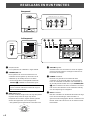
Nonskid pads
Patins anti-dérapages
Rutschfeste Auflagen
Glidskyddsdynor
Piedini antisdrucciolevoli
Almohadillas antideslizantes
Niet-glijdende steunen
UNPACKING After unpacking, check that the following item is contained.
DEBALLAGE Après le déballage, vérifier que la pièce suivante est incluse.
AUSPACKEN Nach dem Auspacken überprüfen, ob das folgende Teil vorhanden ist.
UPPACKNING Kontrollera efter det apparaten packats upp att följande del finns med.
DISIMBALLAGGIO Verificare che l’accessorio sotto sia contenuto nell’imballaggio dell’apparecchio.
DESEMBALAJE Desembale el aparato y verifique que el siguiente accesorio está en la caja.
UITPAKKEN Controleer na het uitpakken of de volgende onderdelen voorhanden zijn.
For U.K. customers
If the socket outlets in the home are not suitable for the plug
supplied with this appliance, it should be cut off and an
appropriate 3 pin plug fitted. For details, refer to the
instructions described below.
Note: The plug severed from the mains lead must be
destroyed, as a plug with bared flexible cord is hazardous if
engaged in a live socket outlet.
SPECIAL INSTRUCTIONS FOR U.K. MODEL
IMPORTANT:
THE WIRES IN MAINS LEAD ARE COLOURED IN
ACCORDANCE WITH THE FOLLOWING CODE:
Blue: NEUTRAL
Brown: LIVE
As the colours of the wires in the mains lead of this
apparatus may not correspond with the coloured markings
identifying the terminals in your plug, proceed as follows:
The wire which is coloured BLUE must be connected to
the terminal which is marked with the letter N or coloured
BLACK. The wire which is coloured BROWN must be
connected to the terminal which is marked with the letter L
or coloured RED. Making sure that neither core is
connected to the earth terminal of the three pin plug.

English
E-1
Please read the following operating precautions before use.
YAMAHA will not be held responsible for any damage
and/or injury caused by not following the cautions below.
● To assure the finest performance, please read this
manual carefully. Keep it in a safe place for future
reference.
● Install this unit in a cool, dry, clean place – away from
windows, heat sources, sources of excessive vibration,
dust, moisture and cold. Avoid sources of humming
(transformers, motors). To prevent fire or electrical
shock, do not expose this unit to rain or water.
● Never open the cabinet. If something drops into the set,
contact your dealer.
● The voltage to be used must be the same as that
specified on the rear panel. Using this unit with a higher
voltage than specified is dangerous and may cause a
fire and/or electric shock.
● To reduce the risk or fire or electric shock, do not expose
this unit to rain or moisture.
● Do not use force on switches, controls or connection
wires. When moving the unit, first disconnect the power
plug and the wires connected to other equipments.
Never pull the wires themselves.
● When not planning to use this unit for a long period (ie.,
vacation, etc.), disconnect the AC power plug from the
wall outlet.
● To prevent lightning damage, disconnect the AC power
plug when there is an electric storm.
● Since this unit has a built-in power amplifier, heat will
radiate from the rear panel. Place the unit apart from the
walls, allowing enough spaces above, behind and on
both sides of the unit to prevent fire or damage.
Furthermore, do not position with the rear panel facing
down on the floor or other surfaces.
<For U.K. and Europe models only>
Be sure to allow spaces of at least 20 cm above, behind
and on both sides of the unit.
● Do not cover the rear panel of this unit with a
newspaper, a tablecloth, a curtain, etc. in order not to
obstruct heat radiation. If the temperature inside the unit
rises, it may cause fire, damage to the unit and/or
personal injury.
●
Do not place small metallic objects on this unit.
Otherwise, the object may fall, possibly causing an injury.
● Do not place the following objects on this unit:
Glass, china, etc.
If glass etc. falls by vibrations and breaks, it may cause
personal injury.
A burning candle etc.
If the candle falls by vibrations, it may cause fire and
personal injury.
A vessel with water in it
If the vessel falls by vibrations and water spills, it may
cause damage to the unit, and/or you may get an
electric shock.
● Do not place this unit where foreign objects such as
water drips might fall. It might cause a fire, damage to
this unit, and/or personal injury.
● Never place a fragile object near the YST port of this
unit. If the object falls or drops by the air pressure, it may
cause damage to the unit and/or personal injury.
● Never put a hand or a foreign object into the YST port
located on the right side of this unit. When moving this
unit, do not hold the port as it might cause personal
injury and/or damage to this unit.
● The household breaker might go off unexpectedly when
a high level signal is inputted to this unit. In this case,
turn down the volume on the amplifier etc. connected to
this unit or cut off the power to other unused equipment.
● Never open the cabinet. It might cause an electric shock
since this unit uses a high voltage. It might also cause
personal injury and/or damage to this unit.
● When using a humidifier, be sure to avoid condensation
inside this unit by allowing enough spaces around this
unit or avoiding excess humidification. Condensation
might cause a fire, damage to this unit, and/or electric
shock.
● Super-bass frequencies reproduced by this unit may
cause a turntable to generate a howling sound. In such a
case, move this unit away from the turntable.
● This unit may be damaged if certain sounds are
continuously outputted at high volume level. For
example, if 20 Hz–50 Hz sine waves from a test disc,
bass sounds from electronic instruments, etc. are
continuously outputted, or when the stylus of a turntable
touches the surface of a disc, reduce the volume level to
prevent this unit from being damaged.
● If you hear distorted noise (i.e., unnatural, intermittent
“rapping” or “hammering” sounds) coming from this unit,
reduce the volume level. Extremely loud playing of a
movie soundtrack’s low frequency, bass-heavy sounds or
similarly loud popular music passages can damage this
speaker system.
● Vibration generated by super-bass frequencies may
distort images on a TV. In such a case, move this unit
away from the TV set.
● Do not attempt to clean this unit with chemical solvents
as this might damage the finish. Use a clean, dry cloth.
● Be sure to read the “TROUBLESHOOTING” section
regarding common operating errors before concluding
that the unit is faulty.
● Secure placement or installation is the owner’s
responsibility.
YAMAHA shall not be liable for any accident caused
by improper placement or installation of speakers.
Standby mode
When this unit is turned off by pressing the STANDBY/ON
button on the front panel, this unit consumes a small
amount of power. This state is called the standby mode.
This unit’s power supply is completely cut off from the AC
line only when the POWER switch on the rear panel is set
in the OFF position or the AC power cord is disconnected.
This unit features a magnetically shielded design, but
there is still a chance that placing it too close to a TV set
might impair picture color. Should this happen, move this
unit away from the TV set.
CAUTION: Read this before operating your unit.
Thank you for selecting this YAMAHA Subwoofer System.

E-2
CONTENTS
UNPACKING................ Inside of Front Cover
CAUTION ..................................................1
FEATURES ...............................................2
PLACEMENT ............................................3
CONNECTIONS....................................... 4
Connecting to line output (pin jack)
terminals of the amplifier ....................... 4
Connecting to speaker output terminals
of the amplifier....................................... 6
CONTROLS AND THEIR FUNCTIONS... 8
AUTOMATIC POWER-SWITCHING
FUNCTION............................................... 9
ADJUSTING THE SUBWOOFER
BEFORE USE........................................ 10
Frequency characteristics.................... 11
ADVANCED YAMAHA ACTIVE SERVO
TECHNOLOGY...................................... 12
TROUBLESHOOTING........................... 13
SPECIFICATIONS ................................. 14
FEATURES
● This subwoofer system employs Advanced
YAMAHA Active Servo Technology which YAMAHA
has developed for reproducing higher quality
super-bass sound. (Refer to page 12 for details on
Advanced YAMAHA Active Servo Technology.) This
super-bass sound adds a more realistic, theater-in-
the-home effect to your stereo system.
● This subwoofer can be easily added to your
existing audio system by connecting to either the
speaker terminals or the line output (pin jack)
terminals of the amplifier.
● For the effective use of this unit, this unit’s super-
bass sound should be matched to the sounds of
your main speakers. You can create the best sound
quality for various listening conditions by using the
HIGH CUT control and the PHASE switch.
● The Automatic power-switching function saves you
the trouble of pressing the STANDBY/ON button to
turn the power on and off.
● You can select bass effect suitable for the source
by using the BASS switch.

English
E-3
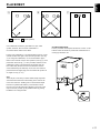
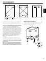
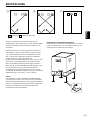
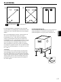
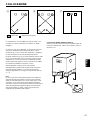
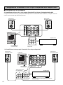
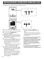
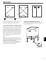
PLACEMENT
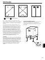
One subwoofer will have a good effect on your audio
system, however, the use of two subwoofers is
recommended to obtain more effect.
If using one subwoofer, it is recommended to place it on the
outside of either the right or the left main speaker. (See fig.
Å.) If using two subwoofers, it is recommended to place
them on the outside of each main speaker. (See fig. ı.) The
placement shown in fig. Ç is also possible, however, if the
subwoofer system is placed directly facing the wall, the
bass effect may die because the sound from it and the
sound reflected by the wall may cancel out each other. To
prevent this from happening, face the subwoofer system at
an angle as in fig. Å or ı.
Note
There may be a case that you cannot obtain enough super-bass
sounds from the subwoofer when listening in the center of the
room. This is because “standing waves” have been developed
between two parallel walls and they cancel the bass sounds.
In such a case, face the subwoofer obliquely to the wall. It also
may be necessary to break up the parallel surfaces by placing
bookshelves etc. along the walls.
( : subwoofer, : main speaker)
Use the nonskid pads
Put the provided nonskid pads at the four corners on the
bottom of the subwoofer to prevent the subwoofer from
moving by vibrations etc.
Çı
Å

E-4
BASS
MUSIC NORMMOVIE REV HIGH
LOW
OFF
PHASE AUTO
STANDBY
OUTPUT
TO SPEAKERS
INPUT
1
INPUT
2
FROM AMPLIFIER
/MONO
ON
POWER
OFF
SPLIT SUBWOOFER
SUBWOOFER
(LOW PASS)
OUTPUT
TO SPEAKERS
/MONO
INPUT
1
INPUT
2
FROM AMPLIFIER
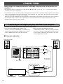
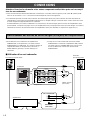
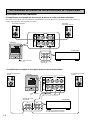
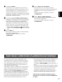
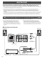
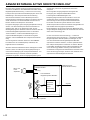
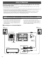
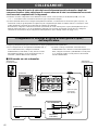
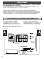
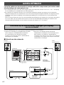
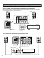
CONNECTIONS
Caution: Plug in the subwoofer and other audio/video components after all connections are
completed.
● All connections must be correct, that is to say L (left) to L, R (right) to R, “+” to “+” and “–” to “–”. Also refer to the owner’s
manual for each of your components.
● The subwoofer can be connected to either the line output (pin jack) terminals or the speaker output terminals of the amplifier.
Choose one of the ways shown in this section that is more suitable for your audio system. Also, refer to the owner’s manual
of your component to be connected to the subwoofer.
Basically, connect the subwoofer to the line output (pin jack) terminal(s) of the amplifier. (Refer to pages 4 and 5 for details.)
If your amplifier does not have any line output terminal, connect the subwoofer to the speaker output terminals of the
amplifier. (Refer to pages 6 and 7 for details.)
Subwoofer
Amplifier
To AC outlet
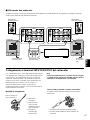
● To connect with a YAMAHA DSP amplifier (or AV
receiver), connect the SUBWOOFER (or LOW PASS etc.)
terminal on the rear of the DSP amplifier (or AV receiver)
to the L/MONO INPUT2 terminal of the subwoofer.
Connect the main speakers to the speaker output terminals of the amplifier.
● When connecting the subwoofer to the SPLIT
SUBWOOFER terminals on the rear of the DSP amplifier,
be sure to connect the L/MONO INPUT2 terminal to the
“L” side and the R INPUT2 terminal to the “R” side of the
SPLIT SUBWOOFER terminals.
Pin plug cord
(not included)
Connecting to line output (pin jack) terminals of the amplifier
m Using one subwoofer
Left main speaker
Right main speaker

English
E-5
ON
POWER
OFF
BASS
MUSIC NORMMOVIE REV HIGH
LOW
OFF
PHASE AUTO
STANDBY
OUTPUT
TO SPEAKERS
INPUT
1
INPUT
2
FROM AMPLIFIER
/MONO
BASS
MUSIC NORMMOVIE REV HIGH
LOW
OFF
PHASE AUTO
STANDBY
OUTPUT
TO SPEAKERS
INPUT
1
INPUT
2
FROM AMPLIFIER
/MONO
ON
POWER
OFF
SPLIT SUBWOOFER
OUTPUT
TO SPEAKERS
INPUT
1
INPUT
2
FROM AMPLIFIER
OUTPUT
TO SPEAKERS
INPUT
1
INPUT
2
FROM AMPLIFIER
/MONO /MONO
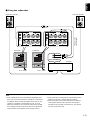
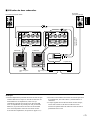
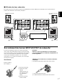
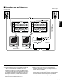
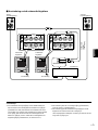
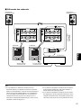
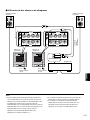
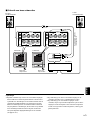
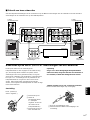
m Using two subwoofers
Notes
● Some amplifiers have line output terminals labeled PRE OUT.
When you connect the subwoofer to the PRE OUT terminals of
the amplifier, make sure that the amplifier has at least two sets
of PRE OUT terminals. If the amplifier has only one set of
PRE OUT terminals, do not connect the subwoofer to the PRE
OUT terminals. Instead, connect the subwoofer to the speaker
output terminals of the amplifier. (Refer to pages 6 and 7.)
● When connecting to a monaural line output terminal of the
amplifier, connect the L/MONO INPUT2 terminal.
● When connecting to line output terminals of the amplifier,
other speakers should not be connected to the OUTPUT
terminals on the rear panel of the subwoofer. If connected,
they will not produce sound.
Subwoofer
Amplifier
To AC outlet
Pin plug cords
(not included)
Left main speaker
Right main speaker
Subwoofer
To AC outlet

E-6
AB
BASS
MUSIC NORMMOVIE REV HIGH
LOW
OFF
PHASE AUTO
STANDBY
OUTPUT
TO SPEAKERS
INPUT
1
INPUT
2
FROM AMPLIFIER
/MONO
ON
POWER
OFF
OUTPUT
TO SPEAKERS
INPUT
1
INPUT
2
FROM AMPLIFIER
/MONO
BASS
MUSIC NORMMOVIE REV HIGH
LOW
OFF
PHASE AUTO
STANDBY
OUTPUT
TO SPEAKERS
INPUT
1
INPUT
2
FROM AMPLIFIER
/MONO
ON
POWER
OFF
OUTPUT
TO SPEAKERS
INPUT
1
INPUT
2
FROM AMPLIFIER
/MONO
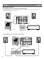
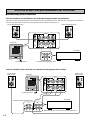
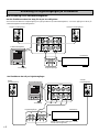
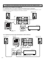
Connecting to speaker output terminals of the amplifier
m Using one subwoofer
If your amplifier has only one set of main speaker output terminals
Connect the speaker output terminals of the amplifier to the INPUT1 terminals of the subwoofer, and connect the OUTPUT
terminals of the subwoofer to the main speakers.
Left main speakerRight main speaker
Subwoofer
Amplifier
Speaker output
terminals
To AC outlet
If your amplifier has two sets of speaker output terminals
(Both A and B speaker outputs must be ON.)
Left main speakerRight main speaker
Subwoofer
Amplifier
Speaker output
terminals
To AC outlet

English
E-7
BASS
MUSIC NORMMOVIE REV HIGH
LOW
OFF
PHASE AUTO
STANDBY
OUTPUT
TO SPEAKERS
INPUT
1
INPUT
2
FROM AMPLIFIER
/MONO
ON
POWER
OFF
BASS
MUSIC NORMMOVIE REV HIGH
LOW
OFF
PHASE AUTO
STANDBY
OUTPUT
TO SPEAKERS
INPUT
1
INPUT
2
FROM AMPLIFIER
/MONO
ON
POWER
OFF
OUTPUT
TO SPEAKERS
INPUT
1
INPUT
2
FROM AMPLIFIER
OUTPUT
TO SPEAKERS
INPUT
1
INPUT
2
FROM AMPLIFIER
/MONO
/MONO
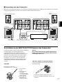
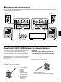
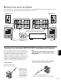
m Using two subwoofers
Connect the speaker output terminals of the amplifier to the INPUT1 terminals of the subwoofer, and connect the OUTPUT
terminals of the subwoofer to the main speakers.
Left main speakerRight main speaker
Subwoofer
Speaker output
terminals
To AC outlet
Subwoofer
To AC outlet
Amplifier
For connections, keep the speaker cords as short as
possible. Do not bundle or roll up the excess part of the
cords. If the connections are faulty, no sound will be heard
from the subwoofer or the speakers, or both of them. Make
sure that the + and – polarity markings of the speaker cords
are observed and set correctly. If these cords are reversed,
the sound will be unnatural and lack bass.
How to Connect:
Red: positive (+)
Black: negative (–)
1 Loosen the knob.
2 Insert the bare wire.
[Remove approx.
10 mm (3/8”)
insulation from the
speaker wires.]
3 Tighten the knob
and secure the wire.
Caution
Do not let the bare speaker wires touch each other as
this could damage the subwoofer or the amplifier, or
both of them.
<U.S.A., Canada and Australia models only>
Banana Plug connections are also possible.
1 Tighten the terminal knob.
2 Simply insert the Banana Plug connector into the
terminal.
Connecting to the INPUT1/OUTPUT terminals of the subwoofer
1
2
3
1
2

E-8
BASS
MUSIC NORMMOVIE REV HIGH
LOW
OFF
PHASE AUTO
STANDBY
OUTPUT
TO SPEAKERS
INPUT
1
INPUT
2
FROM AMPLIFIER
/MONO
ON
POWER
OFF
SUPERWOOFER SYSTEM YST–SW800
STANDBY/ON VOLUME0
–
10HIGH CUT40
–
140Hz
STANDBY/ON VOLUME
0
–
10
HIGH CUT
40
–
140Hz
1 2 3 4
OUTPUT
TO SPEAKERS
INPUT
1
INPUT
2
FROM AMPLIFIER
BASS
MUSIC NORMMOVIE REV HIGH
LOW
OFF
PHASE AUTO
STANDBY
6 07 8
A
/MONO
9
ON
POWER
OFF
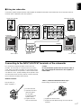
5
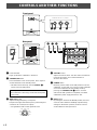
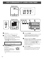
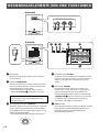
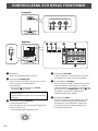
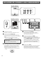
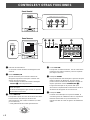
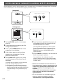
1 Power indicator
Lights up while the subwoofer is turned on.
2 STANDBY/ON button
Press this button to turn on the power. Press again to
set the subwoofer in the standby mode.
* This button can be used only when the POWER (5)
switch is set in the ON position.
Standby mode
The subwoofer is still using a small amount of power
in this mode.
3 HIGH CUT control
Adjusts the high frequency cut off point.
Frequencies higher than the frequency selected by this
control are all cut off (and no output).
* One graduation of this control represents 10 Hz.
4 VOLUME control
Adjusts the volume level. Turn the control clockwise to
increase the volume, and counterclockwise to
decrease the volume.
5 POWER switch
Normally, set this switch to the ON position to use the
subwoofer. In this state, you can turn on the subwoofer
or turn the subwoofer into the standby mode by
pressing the STANDBY/ON (2) button. Set this
switch to the OFF position to completely cut off the
subwoofer’s power supply from the AC line.
6 BASS switch
By setting this switch to the MOVIE position, the bass
sound in video software is faithfully reproduced. By
setting it to the MUSIC position, the bass sound in
audio software is well reproduced.
Rear panel
CONTROLS AND THEIR FUNCTIONS
40Hz
50Hz
60Hz 120Hz
70Hz 110Hz
80Hz 100Hz
90Hz
130Hz
140Hz
Front panel

English
E-9
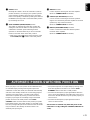
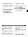
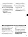
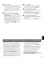
When you play a source, the power of the subwoofer turns
on automatically by sensing audio signals input to the
subwoofer. On the other hand, the subwoofer automatically
switches to the standby mode if the source being played is
stopped or the input signal is cut off for a few minutes.
This function operates by sensing a certain level of low
frequency input signal. Its sensitivity is high in the HIGH
position and low in the LOW position of the AUTO
STANDBY switch. Set this switch to the position you prefer.
In the HIGH position, the power will turn on even with a low
level of input signal. But please be aware that the subwoofer
may not switch to the standby mode when there is an
extremely low input signal.
* The power might turn on unexpectedly by sensing noise
from other appliances. If that occurs, set the AUTO
STANDBY switch to the OFF or LOW position.
* The level of low frequency input signal differs with each
source and among different parts within the same source.
This means that the function may not operate properly on
some sources.
* The level of low frequency input signal this function
senses is about 100 Hz.
This function is available only when the power of the
subwoofer is on (by setting the STANDBY/ON button to
“ON”).
7 PHASE switch
Normally this switch is to be set to the REV (reverse)
position. However, according to your speaker systems
or the listening condition, there may be a case when
better sound quality is obtained by setting this switch to
the NORM (normal) position. Select the better position
by monitoring the sound.
8 AUTO STANDBY (HIGH/LOW/OFF) switch
This switch is originally set to the OFF position. By
setting this switch to the HIGH or LOW position, the
subwoofer’s automatic power-switching function
operates as described below. If you do not need this
function, leave this switch in the OFF position.
* Make sure to change the setting of this switch only when
the STANDBY/ON (2) button is in the OFF position.
9 INPUT2 terminals
Used to input line level signals from the amplifier.
(Refer to “CONNECTIONS” for details.)
0 OUTPUT (TO SPEAKERS) terminals
Can be used for connecting to the main speakers.
Signals are sent directly from the amplifier to the main
speakers by way of these terminals.
(Refer to “CONNECTIONS” for details.)
A INPUT1 (FROM AMPLIFIER) terminals
Used to connect the subwoofer with the speaker
terminals of the amplifier.
(Refer to “CONNECTIONS” for details.)
AUTOMATIC POWER-SWITCHING FUNCTION

E-10
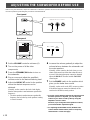
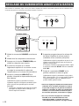
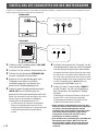
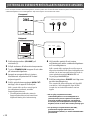
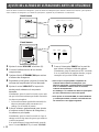
1 Set the VOLUME control to minimum (0).
2 Turn on the power of all the other
components.
3 Press the STANDBY/ON button to turn on
the subwoofer.
4 Play a source and adjust the amplifier’s
volume control to the desired listening level.
5 Adjust the HIGH CUT control to the position
where the desired response can be
obtained.
Normally, set the control to the level a little higher
than the main speaker’s rated minimum reproducible
frequency*.
* The main speaker’s rated minimum reproducible
frequency can be looked up in the speakers’ catalog
or owner’s manual.
Before using the subwoofer, adjust the subwoofer to obtain the optimum volume and tone balance between the subwoofer and
the main speakers by following the procedures described below.
6 Increase the volume gradually to adjust the
volume balance between the subwoofer and
the main speakers.
Normally, set the control to the level where you can
obtain a little more bass effect than when this unit is
not used. If the desired response cannot be obtained,
adjust the HIGH CUT control and the VOLUME
control again.
7 Set the PHASE switch to the position which
gives you the better bass sound.
Normally, set the switch to the REV (reverse) position.
If the desired response cannot be obtained, set the
switch to the NORM (normal) position.
● Once the volume balance between the subwoofer and
the main speakers is adjusted, you can adjust the
volume of your whole sound system by using the
amplifier’s volume control.
However, if you change the main speakers to others,
you must make this adjustment again.
● For adjusting the VOLUME control, the HIGH CUT
control and the PHASE switch, refer to “Frequency
characteristics” on the next page.
ADJUSTING THE SUBWOOFER BEFORE USE
Rear panel
Front panel
BASS
MUSIC NORMMOVIE REV HIGH
LOW
OFF
PHASE AUTO
STANDBY
OUTPUT
TO SPEAKERS
INPUT
1
INPUT
2
FROM AMPLIFIER
/MONO
ON
POWER
OFF
SUPERWOOFER SYSTEM YST–SW800
STANDBY/ON VOLUME0
–
10HIGH CUT40
–
140Hz
STANDBY/ON VOLUME
0
–
10
HIGH CUT
40
–
140Hz
BASS
MUSIC NORMMOVIE REV HIGH
LOW
OFF
PHASE AUTO
STANDBY
3
7
5

English
E-11
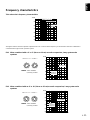
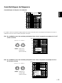
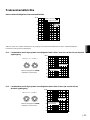
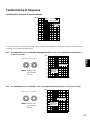
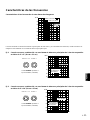
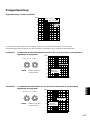
Frequency characteristics
This subwoofer’s frequency characteristics
EX.1 When combined with a 4” or 5” (10 cm or 13 cm) acoustic suspension, 2 way system main
speakers
EX.2 When combined with an 8” or 10” (20 cm or 25 cm) acoustic suspension, 2 way system main
speakers
PHASE–Set to the REV
(reverse) position.
The figures below show the optimum adjustment of each control and the frequency characteristics when this subwoofer is
combined with a typical main speaker system.
PHASE–Set to the REV
(reverse) position.
VOLUME
0
–
10
HIGH CUT
40
–
140Hz
VOLUME
0
–
10
HIGH CUT
40
–
140Hz
20 50 100 200 500 Hz
40
50
60
70
80
90
100 dB
HIGH CUT 40 Hz
HIGH CUT 90 Hz
HIGH CUT
140 Hz
20 50 100 200 500 Hz
40
50
60
70
80
90
100 dB
YST-SW320
20 50 100 200 500 Hz
40
50
60
70
80
90
100 dB
YST-SW320
Main
speaker’s
response
Main
speaker’s
response
YST-SW800
YST-SW800

E-12
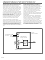
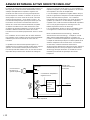
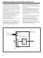
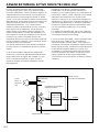
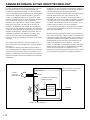
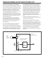
ADVANCED YAMAHA ACTIVE SERVO TECHNOLOGY
The theory of Yamaha Active Servo Technology has been
based upon two major factors, the Helmholtz resonator and
negative-impedance drive. Active Servo Processing
speakers reproduce the bass frequencies through an “air
woofer”, which is a port or opening in the speaker’s cabinet.
This opening is used instead of, and performs the functions
of, a woofer in a conventionally designed speaker system.
Thus, signals of low amplitude within the cabinet can,
according to the Helmholtz resonance theory, be outputted
from this opening as waves of great amplitude if the size of
the opening and the volume of the cabinet are in the correct
proportion to satisfy a certain ratio.
In order to accomplish this, moreover, the amplitudes within
the cabinet must be both precise and of sufficient power
because these amplitudes must overcome the “load”
presented by the air that exists within the cabinet.
Thus it is this problem that is resolved through the
employment of a new design in which the amplifier supplies
special signals. If the electrical resistance of the voice coil
could be reduced to zero, the movement of the speaker unit
would become linear with respect to signal voltage. To
accomplish this, a special negative-impedance output-drive
amplifier for subtracting output impedance of the amplifier is
used.
By employing negative-impedance drive circuits, the
amplifier is able to generate precise, low-amplitude, low-
frequency waves with superior damping characteristics.
These waves are then radiated from the cabinet opening as
high-amplitude signals. The system can, therefore, by
employing the negative-impedance output drive amplifier
and a speaker cabinet with the Helmholtz resonator,
reproduce an extremely wide range of frequencies with
amazing sound quality and less distortion.
The features described above, then, are combined to be the
fundamental structure of the conventional Yamaha Active
Servo Technology.
Our new Active Servo Technology — Advanced Yamaha
Active Servo Technology — adopted Advanced Negative
Impedance Converter (ANIC) circuits, which allows the
conventional negative impedance converter to dynamically
vary in order to select an optimum value for speaker
impedance variation. With this new ANIC circuits, Advanced
Yamaha Active Servo Technology can provide more stable
performance and improved sound pressure compared with
the conventional Yamaha Active Servo Technology, resulting
in more natural and dynamic bass reproduction.
High-amplitude
bass sound
Cabinet
Port
Air woofer
(Helmholtz resonator)
Active Servo
Processing
Amplifier
Signals
Signals of low amplitude
Advanced Negative-
impedance Converter

English
E-13
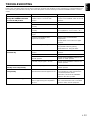
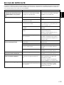
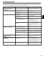
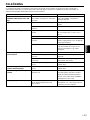
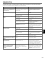
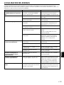
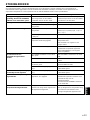
Problem
Power is not supplied even
though the STANDBY/ON button
is set to the ON position.
No sound.
Sound level is too low.
The subwoofer does not turn on
automatically.
The subwoofer turns into the
standby mode unexpectedly.
The subwoofer turns on
unexpectedly.
The household breaker goes off.
What to Do
Plug the power cord into an AC outlet
and/or set the POWER switch to the ON
position.
Turn the VOLUME control to the right.
Connect them securely.
Connect them correctly, that is L (left) to
L, R (right) to R, “+” to “+” and “–” to “–”.
Set the switch to the other position.
Play a source sound with bass
frequencies.
Set the HIGH CUT control to a higher
position.
Reposition the subwoofer or break up
the parallel surface by placing
bookshelves etc. along the walls.
Set the POWER switch to the ON
position.
Set the STANDBY/ON button to ON.
Set the AUTO STANDBY switch to the
“HIGH” or “LOW” position.
Set the AUTO STANDBY switch to the
“HIGH” position.
Set the AUTO STANDBY switch to the
“HIGH” position.
Move the subwoofer farther away from
such appliances and/or reposition the
connected speaker cables.
Otherwise, set the AUTO STANDBY
switch to the “OFF” position.
Turn down the volume on the amplifier
etc. connected to this unit or cut off the
power to other unused equipment.
Cause
The power cord is not plugged in, or the
POWER switch is set to the OFF
position.
The VOLUME control is set to 0.
Speaker cords are not connected
securely.
Speaker cords are not connected
correctly.
Setting of the PHASE switch is not
proper.
A source sound with few bass
frequencies is played.
It is influenced by standing waves.
The POWER switch is set to the OFF
position.
The STANDBY/ON button is set to OFF.
The AUTO STANDBY switch is set to
the OFF position.
The level of input signal is too low.
The level of input signal is too low.
There is an influence of noise
generated from external appliances etc.
This unit consumes much electricity
when a high level signal is inputted to
this unit.
TROUBLESHOOTING
Refer to the chart below when this unit does not function properly. If the problem you are experiencing is not listed below or if
the instructions given below do not help, disconnect the power cord and contact your authorized YAMAHA dealer or service
center.

E-14
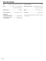
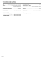
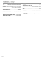
SPECIFICATIONS
Type ............... Advanced Yamaha Active Servo Technology
Driver...........................25 cm (10”) cone woofer (JA25610)
Magnetically shielded type
Amplifier Output.................................................. 800W/6Ω
Frequency Response................... 18 Hz–160 Hz (–10 dB)
Power Supply
USA and Canada models .......................AC 120V, 60 Hz
U.K. and Europe models ........................AC 230V, 50 Hz
Australia model....................................... AC 240V, 50 Hz
Power Consumption .................................................250W
Dimensions (W x H x D)...... 390 mm x 482 mm x 420 mm
(15-3/8” x 19” x 16-9/16”)
Weight ................................................24 kg (52 lbs. 13 oz.)
Accessories .............................................. Nonskid pad x 4
* Please note that all specifications are subject to change
without notice.

F-1
Français
Veuillez lire les précautions suivantes avant toute utilisation.
YAMAHA ne se tiendra pas responsable d'aucun dommage
et/ou d’aucune blessure causés en ne suivant pas les
avertissements ci-sessous.
●
Installer l’appareil dans un endroit frais, sec et propre, loin de
fenêtres, sources de chaleur et d’endroits où les vibrations, la
poussière, l’humidité ou le froid sont importants. Eviter les
sources de bourdonnements (transformateurs, moteurs). Pour
éviter les incendies ou électrocution, ne pas exposer l’appareil
à la pluie ni à l’humidité.
●
Ne jamais ouvrir le coffret. Si un objet pénètre dans l’appareil,
contacter son revendeur.
●
Le voltage à utiliser doit être le même que celui spécifié sur le
panneau arrière. Utiliser l’appareil avec un plus haut voltage que
spécifié est dangeraux et peut causer un feu et/ou une
électrocution.
●
Afin d’éviter tout risque d’incendie ou d’électrocution, ne pas
exposer l’appareil à la pluie ni à l’humidité.
●
Ne pas forcer les commutateurs, les touches ou les câbles de
raccordement.
Lors du déplacement de l’appareil, d’abord débrancher la prise
d’alimentation et les câbles le raccordant à d’autres appareils.
Ne jamais tirer sur les cordons.
●
Lorsqu’on prévoit de ne pas utiliser cet appareil pendant
longtemps (pendant les vacances, par exemple), débrancher le
cordon d’alimentation CA de la prise murale.
●
Pour prévenir tout dégât dû à la foudre, débrancher la prise
d’alimentation CA en cas d’orage.
●
Cet appareil possédant un amplificateur intégré, de la chaleur
sera irradiée par le panneau arrière. Par conséquent, placer
l’appareil à une certaine distance des murs, en laissant
suffisamment d’espace au-dessus, derrière et des deux côtés
de l’appareil afin d’éviter tout risque de dommage ou
d’incendie. Ne pas positionner non plus cet appareil dos au
plancher ou à une autre surface.
<Modèles pour le Royaume-Uni et l’Europe
seulement>
Laisser un espace d’au moins 20 cm au-dessus, derrière et
des deux côtés de l’appareil.
●
Ne pas couvrir le panneau arrière de cet appareil avec un
journal, une nappe, un rideau, etc., afin de ne pas empêcher le
rayonnement de chaleur. Si la température s’élève à l’intérieur
de l’appareil, ceci risque de causer un incendie,
d’endommager l’appareil et/ou de provoquer des blessures
corporelles.
●
Ne pas placer de petits objets métalliques sur l’appareil. Ils
pourraient tomber et risqueraient de causer une blessure.
●
Ne placez pas les objets suivants sur l’appareil:Verres,
porcelaine, etc.
Si les verres, etc., tombent sous l’effet des vibrations et se
rompent, ceci risque de causer des blessures.
Une bougie allumée, etc.
Si la bougie tombe sous l’effet des vibrations, ceci risque de
causer un incendie et des blessures.
Un récipient contenant de l’eau
Si le récipient tombe sous l’effet des vibrations et que l’eau
se répand, ceci risque d’endommager l’appareil et/ou de
causer une électrocution.
●
Ne pas placer l’appareil dans un endroit où des corps étrangers
comme des gouttes d'eau peuvent tomber. Ceci peut causer un
feu, des dommages à l’appareil et/ou une blessure corporelle.
●
Ne jamais placer d’objet fragile à proximité du port YST de
l’appareil. Si l’objet tombe à cause de la pression d’air, il peut
entraîner des dommages à l’appareil et/ou des blessures.
●
Ne jamais introduire la main ou tout corps étranger dans le
port YST situé sur le côté droit de l’appareil. Lors du
déplacement de cet appareil, ne pas le tenir par le port, cela
peut entraîner des blessures et/ou endommager l’appareil.
●
Le disjoncteur du foyer peut disjoncter de manière inattendue
lorsqu’un signal de haut niveau est entré dans l’appareil. Dans
ce cas, baisser le volume de l’amplificateur, etc. connecté à cet
appareil ou mettre tous les appareils inutilisés hors tension.
●
Ne jamais ouvrir le coffret. Cet appareil utilisant un haut
voltage, cela peut entraîner une décharge électrique. Cela peut
également entraîner des blessures et/ou endommager
l’appareil.
●
En utilisant un humidificateur, éviter la condensation
à l’intérieur de l’appareil en libérant la place autour
de l’appareil ou en évitant l’humidification extrême.
La condensation peut causer un feu, des dommages à
l’appareil et/ou une électrocution.
●
Les sons de très basse fréquence produits par cet appareil
peuvent provoquer un sifflement sur le tourne-disque. Dans ce
cas, éloigner cet appareil du tourne-disque.
●
Cet appareil pourra se trouver endommagé si certains sons se
trouvent émis à haut volume de façon continue. Par exemple, si
des ondes sinusoïdales de 20 – 50 Hz d’un disque d’essai, des
sons de basse fréquence d’un instrument électronique, etc.
sont émis continuellement, ou lorsque l’aiguille d’un tourne-
disque est posée sur un disque en rotation, il faut réduire le
volume sonore afin que cet appareil ne soit pas endommagé.
●
Si une distorsion se fait entendre (par exemple des petits
coups secs intermittents ou un “martèlement”) sur cet appareil,
diminuer le niveau sonore. La lecture à très haut volume des
sons de basse ou des sons de basses fréquences de la bande
sonore d’un film, ou de passages de musique populaire de
forte intensité, sont susceptibles d’endommager ce système
d’enceintes.
●
Les vibrations provenant des fréquences très basses peuvent
causer de la distorsion sur l’image d’un téléviseur placé à
proximité. Si c’est la cas, éloigner l’appareil du téléviseur.
●
Ne pas essayer de nettoyer l’appareil avec des diluants
chimiques, ceci endommagerait le fini. Utiliser un chiffon
propre et sec.
●
Bien lire la section “EN CAS DE DIFFICULTE” concernant les
erreurs de fonctionnement communes avant de conclure que
votre appareil est en panne.
●
Le propriétaire du système est entièrement responsable
du bon positionnement et de la bonne installation du
système.
YAMAHA décline toute responsabilité en cas d’accident
causé par un positionnement ou une installation
inadéquats des enceintes.
Mode veille
Lorsque cet appareil est mis hors tension en appuyant sur la
touche STANDBY/ON du panneau avant, l’appareil consomme
une faible quantité de courant. Cet état est appelé mode veille.
L’alimentation électrique de cet appareil est coupée
complètement de la ligne d’alimentation CA seulement
lorsqu’on a mis l’interrupteur POWER du panneau arrière sur
la position OFF ou qu’on a débranché le cordon d’alimentation
CA.
Bien que cet appareil soit doté d’un blindage magnétique, il est
possible que la couleur des images d’un téléviseur placé à
proximité en soit affectée. Dans ce cas, éloigner cet appareil
du téléviseur.
PRECAUTIONS D’USAGE: Tenir compte des précautions ci-dessous avant de
faire fonctionner l’appareil.
Nous vous remercions d’avoir porté votre choix sur ce subwoofer de YAMAHA.

F-2
TABLE DES MATIERES
DEBALLAGE ......Intérieur du couvercle avant
PRECAUTIONS D’USAGE .......................1
CARACTERISTIQUES .............................2
POSITIONNEMENT..................................3
CONNEXIONS ......................................... 4
Raccordement aux bornes de sortie de
ligne (fiche jack) de l’amplificateur
........... 4
Raccordement aux bornes de sortie
d’enceintes de I’amplificateur ................ 6
LES COMMANDES ET LEURS
FONCTIONS ............................................ 8
FONCTION DE COMMUTATION
D’ALIMENTATION AUTOMATIQUE ........ 9
REGLAGE DU SUBWOOFER AVANT
L’UTILISATION ...................................... 10
Caractéristiques de fréquence ............ 11
ADVANCED YAMAHA ACTIVE SERVO
TECHNOLOGY...................................... 12
EN CAS DE DIFFICULTE ...................... 13
CARACTERISTIQUES
TECHNIQUES........................................ 14
CARACTERISTIQUES
● Ce subwoofer utilise Advanced YAMAHA Active
Servo Technology mise au point par YAMAHA pour
la reproduction de basses fréquences de meilleure
qualité. (En ce qui concerne Advanced YAMAHA
Active Servo Technology, se reporter à la page 12.)
Ces basses fréquences ajoutent un effet réaliste
cinématographique aux sons fournis par une
chaîne stéréo.
● Ce subwoofer peut être facilement ajouté à votre
chaîne actuelle en le raccordant soit aux bornes
d’enceintes soit aux bornes de sortie de ligne
(fiche Cinch) de l’amplificateur.
● Pour utiliser au mieux les possibilités de cet
appareil, les basses fréquences de ce subwoofer
doivent être harmonisés avec les sons des
enceintes principales. De plus, il est possible
d’optimiser la qualité sonore suivant les conditions
d’écoute au moyen de la commande HIGH CUT et
du commutateur PHASE.
● La fonction commutation d’alimentation
automatique évite d’avoir à appuyer sur la touche
STANDBY/ON pour mettre le subwoofer sous et
hors tension.
● L’effet de basses peut être réglé en fonction de la
source à l’aide du commutateur BASS.

F-3
Français
POSITIONNEMENT
L’utilisation d’un seul subwoofer dans une chaîne donne
déjà de bons résultats, cependant l’utilisation de deux
subwoofer est recommandée pour accroître l’effet du son.
Lorsqu’on utilise un seul subwoofer, il est recommandé de
le placer sur le côté extérieur de l’enceinte principale droite
ou gauche. (Voir la fig. Å.) Lorsqu’on utilise deux
subwoofer, il est recommandé de les placer sur le côté
extérieur de chacune des enceintes principales. (Voir la fig.
ı.) Il est également possible de positionner les enceintes
comme indiqué à la fig. Ç ; cependant, si le subwoofer est
placé directement contre le mur, l’effet de basse pourra se
trouver supprimé car le son émis par l’enceinte et le son
renvoyé par le mur s’annuleront mutuellement. Pour éviter
ce problème, placer le subwoofer à angle oblique par
rapport au mur, comme indiqué sur la fig. Å ou ı.
Remarque
Les sons de très basses fréquences du subwoofer peuvent
quelquefois être trop faiblement perçus à partir d’une position
d’écoute en milieu de pièce. Les ondes renvoyées par deux murs
parallèles peuvent en effet s’annuler mutuellement et supprimer
les sons de basses.
Dans un tel cas, diriger le subwoofer obliquement par rapport au
mur. Il peut être également nécessaire de modifier le parallélisme
des surfaces murales en plaçant des étagères etc. le long des murs.
( : Subwoofer, : Enceintes principales)
Utiliser les tampons anti-dérapage
Mettre les tampons anti-dérapage fournis aux quatre coins
du bas du subwoofer afin d’empêcher le subwoofer de
bouger sous l’effet des vibrations, etc.
Çı
Å

F-4
BASS
MUSIC NORMMOVIE REV HIGH
LOW
OFF
PHASE AUTO
STANDBY
OUTPUT
TO SPEAKERS
INPUT
1
INPUT
2
FROM AMPLIFIER
/MONO
ON
POWER
OFF
SPLIT SUBWOOFER
SUBWOOFER
(LOW PASS)
OUTPUT
TO SPEAKERS
/MONO
INPUT
1
INPUT
2
FROM AMPLIFIER
CONNEXIONS
Attention: Brancher le subwoofer et les autres composants audio/vidéo après avoir accompli
tous les raccordements.
● Tous les branchements doivent être effectués correctement, c’est-à-dire entre “L” (gauche) et “L”, entre “R” (droite) et “R”,
entre “+” et “+” et entre “–” et “–”. Voir aussi le mode d’emploi de chacun des appareils.
● Le subwoofer peut être raccordé soit aux bornes de sortie de ligne (fiche jack) soit aux bornes de sortie d’enceintes de
l’amplificateur. Choisir parmi les possibilités illustrées dans ce chapitre celle qui convient le mieux à votre chaîne. Voir aussi
le mode d’emploi de l’appareil branché au subwoofer.
Fondamentalement, raccorder le subwoofer à la (aux) borne(s) de sortie de ligne (prise à broche) de l’amplificateur. (Pour
plus de détails, se reporter aux pages 4 et 5.) Si l’amplificateur n’est pas équipé d’une borne de sortie de ligne, raccorder le
subwoofer aux bornes de sortie d’enceintes de l’amplificateur. (Pour plus de détails, se reporter aux pages 6 et 7.)
Subwoofer
Amplificateur
Vers une prise CA
● Pour effectuer le raccordement à un amplificateur
YAMAHA DSP (ou récepteur AV), raccorder la borne
SUBWOOFER (ou LOW PASS, etc.) située à l’arrière de
l’amplificateur DSP (ou récepteur AV) à la borne L/
MONO INPUT2 gauche (L) ou bien droite (R) du
subwoofer.
Raccorder les enceintes principales aux bornes de sortie d’enceintes de l’amplificateur.
● Lorsqu’on raccorde le subwoofer aux bornes SPLIT
SUBWOOFER à l’arrière de l’amplificateur DSP, veiller à
raccorder la borne L/MONO INPUT2 au côté “L” et les
bornes R INPUT2 au côté “R” des bornes SPLIT
SUBWOOFER.
Câbles à fiches
(non inclus)
Raccordement aux bornes de sortie de ligne (fiche jack) de l’amplificateur
m Utilisation d’un seul subwoofer
Enceintes
principale gauche
Enceintes principale droite
Sayfa yükleniyor...
Sayfa yükleniyor...
Sayfa yükleniyor...
Sayfa yükleniyor...
Sayfa yükleniyor...
Sayfa yükleniyor...
Sayfa yükleniyor...
Sayfa yükleniyor...
Sayfa yükleniyor...
Sayfa yükleniyor...
Sayfa yükleniyor...
Sayfa yükleniyor...
Sayfa yükleniyor...
Sayfa yükleniyor...
Sayfa yükleniyor...
Sayfa yükleniyor...
Sayfa yükleniyor...
Sayfa yükleniyor...
Sayfa yükleniyor...
Sayfa yükleniyor...
Sayfa yükleniyor...
Sayfa yükleniyor...
Sayfa yükleniyor...
Sayfa yükleniyor...
Sayfa yükleniyor...
Sayfa yükleniyor...
Sayfa yükleniyor...
Sayfa yükleniyor...
Sayfa yükleniyor...
Sayfa yükleniyor...
Sayfa yükleniyor...
Sayfa yükleniyor...
Sayfa yükleniyor...
Sayfa yükleniyor...
Sayfa yükleniyor...
Sayfa yükleniyor...
Sayfa yükleniyor...
Sayfa yükleniyor...
Sayfa yükleniyor...
Sayfa yükleniyor...
Sayfa yükleniyor...
Sayfa yükleniyor...
Sayfa yükleniyor...
Sayfa yükleniyor...
Sayfa yükleniyor...
Sayfa yükleniyor...
Sayfa yükleniyor...
Sayfa yükleniyor...
Sayfa yükleniyor...
Sayfa yükleniyor...
Sayfa yükleniyor...
Sayfa yükleniyor...
Sayfa yükleniyor...
Sayfa yükleniyor...
Sayfa yükleniyor...
Sayfa yükleniyor...
Sayfa yükleniyor...
Sayfa yükleniyor...
Sayfa yükleniyor...
Sayfa yükleniyor...
Sayfa yükleniyor...
Sayfa yükleniyor...
Sayfa yükleniyor...
Sayfa yükleniyor...
Sayfa yükleniyor...
Sayfa yükleniyor...
Sayfa yükleniyor...
Sayfa yükleniyor...
Sayfa yükleniyor...
Sayfa yükleniyor...
Sayfa yükleniyor...
Sayfa yükleniyor...
Sayfa yükleniyor...
Sayfa yükleniyor...
Sayfa yükleniyor...
Sayfa yükleniyor...
Sayfa yükleniyor...
Sayfa yükleniyor...
Sayfa yükleniyor...
Sayfa yükleniyor...
-
 1
1
-
 2
2
-
 3
3
-
 4
4
-
 5
5
-
 6
6
-
 7
7
-
 8
8
-
 9
9
-
 10
10
-
 11
11
-
 12
12
-
 13
13
-
 14
14
-
 15
15
-
 16
16
-
 17
17
-
 18
18
-
 19
19
-
 20
20
-
 21
21
-
 22
22
-
 23
23
-
 24
24
-
 25
25
-
 26
26
-
 27
27
-
 28
28
-
 29
29
-
 30
30
-
 31
31
-
 32
32
-
 33
33
-
 34
34
-
 35
35
-
 36
36
-
 37
37
-
 38
38
-
 39
39
-
 40
40
-
 41
41
-
 42
42
-
 43
43
-
 44
44
-
 45
45
-
 46
46
-
 47
47
-
 48
48
-
 49
49
-
 50
50
-
 51
51
-
 52
52
-
 53
53
-
 54
54
-
 55
55
-
 56
56
-
 57
57
-
 58
58
-
 59
59
-
 60
60
-
 61
61
-
 62
62
-
 63
63
-
 64
64
-
 65
65
-
 66
66
-
 67
67
-
 68
68
-
 69
69
-
 70
70
-
 71
71
-
 72
72
-
 73
73
-
 74
74
-
 75
75
-
 76
76
-
 77
77
-
 78
78
-
 79
79
-
 80
80
-
 81
81
-
 82
82
-
 83
83
-
 84
84
-
 85
85
-
 86
86
-
 87
87
-
 88
88
-
 89
89
-
 90
90
-
 91
91
-
 92
92
-
 93
93
-
 94
94
-
 95
95
-
 96
96
-
 97
97
-
 98
98
-
 99
99
-
 100
100


diğer dillerde
- español: Yamaha YST-SW800 El manual del propietario
- français: Yamaha YST-SW800 Le manuel du propriétaire
- italiano: Yamaha YST-SW800 Manuale del proprietario
- svenska: Yamaha YST-SW800 Bruksanvisning
- Deutsch: Yamaha YST-SW800 Bedienungsanleitung
- English: Yamaha YST-SW800 Owner's manual
- dansk: Yamaha YST-SW800 Brugervejledning
- Nederlands: Yamaha YST-SW800 de handleiding
- română: Yamaha YST-SW800 Manualul proprietarului