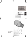
Samsung SCC-101BP Kullanım kılavuzu
- Kategori
- Güvenlik kameraları
- Tip
- Kullanım kılavuzu
Bu kılavuz aynı zamanda aşağıdakiler için de uygundur:

Part No.: AB68-00667A(01)
Printed in Korea
User Guide
Kullanim Klavuzu
SCC
-
130B/131B
SCC
-
130BP/131BP
SCC
-
100BP/101BP
E
TU

1. Read all of these instructions.
2. Save these instruction for later use.
3. Unplug this appliance system from the wall outlet
before cleaning
Do not use liquid cleaners or aerosol cleaner.
Use a damp cloth for cleaning.
4. Do not use attachments not recommended by the
appliance manufacturer, as they may cause
hazards.
5. Do not use this appliance near water for example,
near a bathtub, washbowl, kitchen sink, laundry
tub, in a wet basement, or near a swimming pool,
etc.
6. Do not place this appliance on an unstable cart,
stand, or table.
The appliance may fall causing serious injury to a
child or adult, and serious damage to the
appliance.
Use only with a cart or stand recommended by
the manufacturer’s instructions, and use a
mounting kit approved by the manufacturer.
An appliance and cart combination should be
moved with care. Quick stops, excessive force,
and uneven surfaces may
cause the appliance and cart
combination to overturn.
iii
User Guide
E
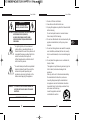
The lightning flash, with an arrowhead
symbol, within an equilateral triangle, is
intended to alert the user to the presence of
uninsulated “dangerous voltage” within the
product’s enclosure, that may be of
sufficient magnitude to constitute a risk of
electric shock to persons.
The exclamation point within an equilateral
triangle is intended to alert the user to the
presence of important operating and
maintenance (servicing) instruction in the
literature accompanying the appliance.
User Guide
ii
CAUTION : TO REDUCE THE RISK OF ELECTRIC SHOCK, DO
NOT REMOVE COVER (OR BACK).
NO USER-SERVICEABLE PARTS INSIDE.
REFER SERVICING TO QUALIFIED SERVICE
PERSONNEL.
RISK OF ELECTRIC
SHOCK, DO NOT OPEN
CAUTION
WARNING : TO PREVENT FIRE OR SHOCK HAZARD, DO
NOT EXPOSE THIS APPLIANCE TO RAIN OR
MOISTURE.
IMPORTANT SAFEGUARDS

13. Unplug this appliance from the wall outlet
and refer servicing to qualified service
personnel under the following conditions:
a. When the power cord or plug is damaged or frayed.
b. If liquid has been spilled into the appliance.
c. If the appliance does not operate normally by
following the operating instructions. Adjust only those
controls that are covered by the operating
instructions, as improper adjustment of other controls
may result in damage and will often require extensive
work by a qualified technician to restore the appliance
to normal operation.
d. If the appliance has been exposed to rain or water.
e. If the appliance has been dropped or the cabinet has
been damaged.
f. When the appliance exhibits a distinct change in
performance this indicates a need for service.
14. When replacement parts are required, be
sure the service technician has used
replacement parts specified by the
manufacturer that have the same
characteristics as the original part.
Unauthorized substitutions may result in fire,
electric shock, or other hazards.
15. Upon completion of any service or repairs to
the appliance, ask the service technician to
perform routine safety checks to determine
that the appliance is in safe operating
condition.
v
User Guide
E
7. Slots and openings in the cabinet on the back or
bottom are provided for ventilation, to insure
reliable operation of the appliance, and to protect
from overheating.
These openings should never be blocked by
placing the appliance on a bed, sofa, rug or other
similar surfaces. This appliance should never be
placed near or over a radiator or heat register.
This appliance should not be place in a built-in
installation such as a bookcase, unless proper
ventilation is provided.
8. This appliance should be operated only from the
type of power source indicated on the marking
label. If you are not sure of the type of power
supplied to your home, consult your dealer or
local power company.
9. Do not allow anything to rest on the power cord.
Do not locate this appliance where the cord will
be abused by people walking on it.
10. Do not overload wall outlets and extension cords,
as this can result in fire or electric shock.
11. Follow all warnings and instructions marked on
the appliance.
12. Do not attempt to service this appliance yourself,
as opening or removing covers may expose you
to dangerous voltage or other hazards. Refer all
servicing to qualified service personnel.
User Guide
iv

Contents
1. Introduction
........................................................
3
2. Features
..............................................................
4
3. Installation
..........................................................
5
Precautions in Installation and Use
....................
5
Connecting Auto Iris Lens Connector
.....................
6
Mounting Lens
.....................................................
7
Setting Lens Selection Switch
............................
8
Adjusting Back Focus
.........................................
9
Connecting Cable
................................................
11
4. Names and Functions of Parts
.......................
14
Names and Functions of Parts
...........................
14
Function Switches
................................................
16
5. Product Specification
.......................................
21
User Guide
2
1. Introduction
Adopting the latest Super -HAD CCD,these cameras
provide the best monitoring function when they are
connected to CCTV system.
❈ In the mechanical fluorescent light environment, if you
attach MANUAL IRIS and turn the ELC switch among
FUNCTION switches on, color may be rolled.
In this case, supply AC power before you turn L/L
switch among FUNCTION switches on.
(NTSC:60HZ , PAL:50HZ)
☞
COLOR ROLLING is the problem that color on the
monitor screen changes non-periodically.
This happens when White Balance is not fixed,
because a mechanical fluorescent light flickers
when it’s cycle is the same to the cycle of the power
frequency.
3
User Guide
E

3. Installation
Precautions in Installation and Use
Do not attempt to disassemble the camera yourself.
Be cautious in handling the camera. Avoid striking or
shaking the camera. Be cautious to avoid damage on
the camera caused by improper storage or operation.
Do not expose this camera to rain or moisture. Do not
operate this camera on a wet place.
Do not use strong or abrasive detergents when
cleaning the camera body.
Use a dry cloth to clean the camera.
Keep the camera at a cool place away from the direct
sunlight. Leaving it under the direct sunlight may result
in the malfunction of the unit.
5
User Guide
E
2. Features
High Sensitivity
Adopting the 1/3" Super HAD CCD that has the latest built-
in microchip lens, the high sensitivity is realized.
Excellent Back Light Compensation
Even when an intense light source or sunlight is in the back
of your subject, a clear image will be provided due to the
ideal combination of the excellent performance of the high
light compression (KNEE Compensation) function and the
BLC (Back Light Compensation) function.
Digital Line-lock
The control and reliability have been enhanced due to the
Full Digital Line Lock, which allows users to adjust the Line
Sync Phase.
Resolution
High resolution is realized due to the Full Digital Image
Processing by the DSP for monitoring camera.
User Guide
4

7
User Guide
E
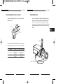
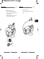
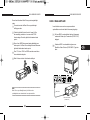
Mounting the Lens
Loosen a screw fixing the Flange Back Adjustment Ring by
turning it counterclockwise and turn the Adjustment Ring to
the "C" direction (counterclockwise) until it stops. Failure to
do so may result in a damage caused by the bump of the lens
against the image sensor part in the camera when mounting
the lens.
C Direction
Auto Iris Control Cable
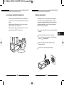
Connecting Auto Iris Lens Connector
Prepare the following Auto Iris Lens Connector supplied
with the camera.
Connect the cable of the control cable, whose covering is
stripped, to the Auto Iris Lens Connector as shown below.
Pin Number DC Control Type Video Control Type
1 Damp(-) Power Source (+9V)
2 Damp(+) Not used
3 Drive(+) Video Signal
4 Drive(-) GND
User Guide
6
Rib
Pin1
Pin2
Pin3
Pin4

9
User Guide
E
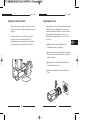
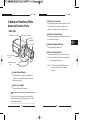
Adjusting Back Focus
Although the Back Focus of the camera has been adjusted
in the factory before its shipment, the focus may not be
accurate for a certain type of the lens. In this case, follow
the procedures below to adjust the Back Focus. First,
following is how to adjust the Back Focus of the Fixed
Focus Lens.
Lightly loosen the screw fixing the Back Focus
Adjustment Ring using a screwdriver.
Image a vivid subject (with check patterns) at a distance
of more than 10m away and turn the Focus Ring to the
infinity ( ) position.
Adjust the Back Focus Adjustment Ring to obtain the
clearest image of the subject.
Fasten the screw fixing the Back Focus Adjustment
Ring.
User Guide
8
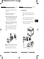
Setting Lens Selection Switch
When lens mounting is completed, set the Lens selection
Switch on the side of the camera according to the mounted
lens type.
When the mounted lens is an Auto Iris Lens of the DC
control type, set the Lens Selection Switch to "DC".
When the mounted lens is an Auto Iris Lens of the Video
control type, set the Lens Selection Switch to "VIDEO".

11
User Guide
E
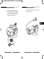
Connecting Cable
After mounting the lens and setting the Lens Selection
Switch, connect the prepared cable to each terminal of the
camera.
First, connect one end of the BNC cable to the Video
Output Terminal (VIDEO OUT) of the camera.
Then connect the other end of the BNC cable to the
Video Input Terminal of the monitor.
Video In Terminal on the rear of the monitor
BNC Cable
Video Out Terminal
(VIDEO OUT)
User Guide
10
The following describes how to adjust the Back Focus when
using a Zoom lens.
Lightly loosen the screw fixing the Back Focus
Adjustment Ring using a screwdriver.
Image a vivid subject (with check patterns) at a distance
of 3~5m away and adjust the zoom of the lens to TELE
as far as it goes. Then adjust the Focus Ring of the
lens to obtain the clearest image of the subject.
Adjust the zoom of the lens to WIDE as far as it goes.
Then turn the Back Focus Ring of the camera to obtain
the clearest image of the subject.
Repeat no. & 2~3 times to exactly coincide the
zoom focus from TELE and with that from WIDE.
Fasten the screw fixing the Back Focus Adjustment
Ring.
Note:
Turning the Back Focus Adjustment Ring to the "C" direction
beyond the adjustable range makes a sound at the limit.

13
User Guide
E
AC230V Power Input Camera
Connect the power input cord to the AC 230V power
source.
User Guide
12
AC24V/DC12V Power Input Camera.
Connect 2 lines of the power adapter using a
Phillips screwdriver to the Power IN Terminal of the
camera as shown below.
Without the distinction of the polarity, connect to
the AC 24V or DC 12V power source.

15
User Guide
E
Auto Iris Lens Connector
Used for supplying power, which is required to control
the iris of the lens, as well as control signal, video
signal, or DC signal to the Auto Iris Control Lens.
Auto Iris Lens Control Cable
Used for transmitting the control signals to the camera
to control the iris of the lens.
Flange-Back Adjustment Ring
Used for adjusting the Back Focus.
ALC Lens Selection Switch
Used when selecting the type of Auto Iris Lens to use.
DC : Select this switch to DC when Iris Lens requiring
DC control signal is mounted.
VIDEO : Select this switch to VIDEO when Auto Iris
Lens requiring VIDEO control signal is
mounted.
User Guide
14
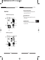
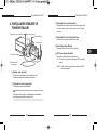
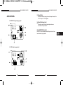
4. Names and Functions of Parts
Names and Functions of Parts
• Side View
Groove for Mount Adapter
Use this groove for fixing the mount adapter to be
connected to the bracket with screws to mount the
camera on the bracket.
Auto Iris Lens (Option)
Lens to be mounted on the camera
Note
When the surface of the camera lens is contaminated,
wipe the surface gently with a tissue for lens or a cotton
cloth applied with ethanol.
# Auto lris Lens Connector
^ ALC Lens Selection
Switch
$ Auto Iris Lens Control
Cable
! Groove for Mount Adapter
@ Auto Iris Lens
%
Flange-Back
Adjustment Ring

Power Connection Terminal
Terminal to be connected to the power (adapter) cable
Connect it to AC 24V or DC 12V.
Power Indication LED
While the power is properly supplied to the camera, the
LED is turned on.
, INC/DEC Switch
The LINELOCK mode is useful for controlling Vertical
Synchronous Phase.
17
User Guide
E
User Guide
16
AC24V/DC12V Power Input Camera
• Rear Panel
AC230V Power Input Camera

19
User Guide
E
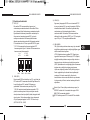
3) SW3 (FL):
This is to prevent flicker on the screen when NTSC
system is used in 50HZ power supply region and PAL
system is used in 60HZ power supply region. That is to
prevent shaking on the screen resulted from the
discordance of the vertical sync frequency and the
flicker frequency of the illumination. While this switch is
ON, the electronic shutter is fixed to 1/100sec (NTSC)
or 1/120 sec (PAL).
4) SW4 (AWB ):
When setting up ON, the color of screen is adjusted
automatically in accordance with the change of lighting
color temperature by the change of outer environment.
(ATW) If the lighting condition is steady, OFF setting is
available. The camera memorizes the lighting color
temperature at the time when the switch setting is
changed from ON to OFF, and the camera color is
adjusted to the memorized color temperature. (AWC)
If the lighting color temperature is changed and you
want to make the camera be memorized/operated with
the changed color temperature, re-operate the switch
On/Off operation. However, be aware that an error may
occur under the following conditions.
First, a case that the subject is big, single color of the
high chroma, and in the center of the screen or a
case with almost no white color on the screen
Second, a case with a specific illumination such as a
natrium lamp
To adjust the Vertical Sync Phase using the INC/DEC
switch in LL mode, the SW4 must be set to AWB “ON”.
For DC 12V, the INT/LL mode is fixed to INT.
User Guide
18
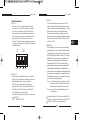
Function Switches
1) SW1 (LL):
When set to OFF, the camera operates in the Internal
Sync mode. When set to ON, it operates in the Power
Sync mode. If the camera is set to INT (Internal Sync)
when monitoring in the Auto Switching mode with more
than one camera connected to a sequential switcher, etc,
the jump of the screen will occur each time of screen
switching. To switch the screen gently without a jump, set
the camera to LL and adjust the Vertical Sync Phase using
the INC/DEC switch.
2) SW2 (ELC):
Use this switch with the Manual Iris Lens. While this
switch is ON, the speed of the electronic shutter varies
with the brightness of the subject from 1/60 to
1/120,000 sec for automatically controlling the
brightness of the screen. However, with the Auto Iris
Lens (DC or Video Control), be sure to switch OFF.
Color Rolling may occur in this mode.
In that case, input AC power source to the camera and
select SW1 “ON”.
(NTSC : 60HZ, PAL : 50HZ)
ON
1. L/L 2. ELC
3. FL 4. AWB
SW1 SW2 SW3 SW4

21
User Guide
E
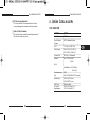
5. Product Specifications
SCC-130B/131B
Item Contents
Product Type CCTV Camera
Broadcasting NTSC STANDARD SYSTEM
System
CCD 1/3” IT type S-HAD CCD
No. of Pixel 130B : 510(H) x 492(V)
131B : 768(H) x 494(V)
Scanning Type 525 Line, 2:1 Interlace
Frequency INTERNAL : 15,734 HZ(H)
59,94 HZ(V)
LINE LOCK :15,750 HZ(H)
60 HZ(V)
Sync Type INTERNAL
LINE LOCK
(When AC24V power source is used)
Resolution 130B : 330TV Lines
131B: 520TV Lines
S/N Ratio 50dB (AGC OFF)
Min. Object 130B : 0.15 Lux (F1.2)
Illumination 131B : 0.3 Lux (F1.2)
DC Iris Level Control
When the ALC Lens Selection Switch is set to DC, adjust
this Iris Level Control using an adjustment rod such as a
screwdriver.
Video Output Terminal
This is a terminal to be connected to the Input Terminal
of the monitor. Through this terminal, the video signals
are outputted.
User Guide
20

23
User Guide
E
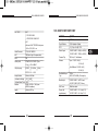
SCC-100BP/101BP/130BP/131BP
Item Contents
Product Type CCTV Camera
Broadcasting PAL STANDARD SYSTEM
System
CCD 1/3” IT type S-HAD CCD
No. of Pixel 100BP/130BP : 500(H) x 582(V)
101BP/131BP : 752(H) x 582(V)
Scanning Type 625 Line, 2:1 Interlace
Frequency INTERNAL : 15,625 HZ(H)
50 HZ(V)
LINE LOCK :15,625 HZ(H)
50 HZ(V)
Sync Type INTERNAL
LINE LOCK
(When AC power source is used)
Resolution 100BP/130BP : 330TV Lines
131BP/101BP: 520TV Lines
S/N Ratio 50dB (AGC OFF)
Min. Object 100BP/130BP : 0.15 Lux (F1.2)
Illumination 131BP/101BP : 0.3 Lux (F1.2)
User Guide
22
ALC /ELC ALC
DC IRIS LENS
VIDEO LENS
ELC
Electronic SHUTTER IRIS function
1/60 to 1/120,000 sec
Color Temperature ATW/AWC Mode
BLC ON(Back Light Compensation)
AGC ON
Video Output COMPOSITE VIDEO OUT
1V p_p 75 /BNC
Power Source AC24V 10%(60Hz 0.3Hz)
DC12V -5% ~ +10%
Power Consumption About 3 Watts
Operating
-10 ~+50
Temperature
Operating
~90%
Humidity
Size 65(W) x 52(H) x 133(L)mm
(BNC included)
Weight 450g

User Guide
E
User Guide
24
ALC /ELC ALC
DC IRIS LENS
VIDEO LENS
ELC
Electronic SHUTTER IRIS function
1/60 to 1/120,000 sec
Color Temperature ATW/AWC Mode
BLC ON(Back Light Compensation)
AGC ON
Video Output COMPOSITE VIDEO OUT
1V p_p 75 /BNC
Power Source 100BP/101BP
AC220V~240V 10%(50Hz 0.3Hz)
130BP/131BP
AC24V 10%(50Hz 0.3Hz)
DC12V -5% ~ +10%
Power Consumption 100BP/101BP: About 4 Watts
130BP/131BP: About 3 Watts
Operating
-10 ~+50
Temperature
Operating
~90%
Humidity
Size 65(W) x 52(H) x 133(L)mm
(BNC included)
Weight 100BP/101BP : About 550g
130BP/131BP : About 450g

1. Talimatlari okuyunuz,
Tüm güvenlik ve kullanim talimatlari cihaz
çalistirilmadan önce okunmalidir
2. Kullanim kilavuzunuzu muhafaza ediniz,
Kullanim kilavuzu ve güvenlik talimatlarini gelecekte de
yararlanabilmek için muhafaza ediniz.
3. Temizleme,
Temizlemeden önce cihazi bagli oldugu prizden
çekiniz. Temizlik için sivi halde bulunan veya
püskürtmeli temizlik maddeleri kullanmayiniz.
Temizlemek için sadece yumusak nemli bir bez
kullaniniz
4. Ekler,
Satici ve/veya üretici firmanin izni olmadan cihaza
herhangi bir cihaz ve/veya eklenti baglamayiniz. Bu gibi
islemler yangin , elektrik çarpmasi veya kisisel
yaralanmalara sebep olabilir.
5. Su ve/veya Nem,
Cihazi kesinlikle bir su kaynagi yakininda veya islak
alanlarda (banyo, yüzme havuzu yani, mutfak, vs.)
kullanmayiniz ve su ile temas etmesinden sakininiz.
6. Aksesuarlar,
Bu cihazi sabit olmayan bir tasiyiciya, standa veya
masaya yerlestirmeyiniz. Yerine uygun konmamasi
cihazin düsmesine, çocuk veya yetiskinlerin
yaralanmasina ve cihazin ciddi bir sekilde zarar
görmesine sebep olabilir. Duvara
veya rafa yerlesimlerde
üretici/satici firmanin vermis oldugu
talimatlara uyunuz ve üretici/satici
firmanin önermis oldugu montaj
setlerini kullaniniz.
iii
KULLANIM KLAVUZU
TU
Eskenar bir üçgen içerisinde asagi bakan ok
ile sonlanan yildirim simgesi, bu
kitapta cihaz/ürün kasasi içerisinde,
kullaniciya elektrik çarpma riski
olusturabilecek malzeme bulundugunu ve
yeterli büyüklükte yalitimsiz “tehlikeli gerilim”
varligi konusunda uyarmak amaciyla
kullanilmistir.
Eskenar bir üçgen içerisinde ünlem isareti
seklindeki simge, kullaniciya düzenek ile
beraber gönderilen basili malzeme
içerisinde önemli çalistirma ve bakim (ikmal)
talimat ve bilgilerinin var oldugunu anlatmak
amaciyla kullanilmistir.
KULLANIM KLAVUZU
ii
D‹KKAT!
ELEKTR‹K ÇARPMA R‹SK‹ VAR! H‹ÇB‹R ZAMAN C‹HAZ
KAPA⁄INI “C‹HAZIN ARKASINI” AÇMAYINIAZ/
ÇIKARMAYINIZ. C‹HAZ KULLANICI TARAFINDAN BAKIM VE
‹KMAL GEREKT‹REN HERHANG‹ B‹R PARÇA ‹ÇERMEZ.
GEREKL‹ BAKIM VE ‹KMAL ÇALEfiMALARI ‹Ç‹N YETK‹L‹
SERV‹S PERSONEL‹NE DANIfiINIZ.
ELEKTR‹K ÇARPMA
R‹SK‹ AÇMAYINIZ
D‹KKAT!!!
UYARI : YANGIN YA DA ELEKTRIK ÇARPMASI RISKLERINDEN
KORUNMAK IÇIN, BU CIHAZI HIÇBIR ZAMAN YAGMUR
YA DA NEME DOGRUDAN MARUZ BIRAKILMAMALIDIR.
ÖNEMLI GÜVENLIK TALIMATLARI

a. Enerji (güç) kablosu veya fisi zarar gördügünde,
b. Eger bir sivi döküldüyse veya cihazin üzerine bir nesne
düstü ise,
c. Eger cihaz yagmur veya suya maruz kaldiysa,
d. Kullanim talimatindaki tüm islemler düzgün ve dogru bir
sekilde uygulanmis olmasina ragmen cihaz normal
fonksiyonlarini yerine getiremiyorsa. Bu durumda kullanim
talimati içerisinde belirtilenler haricinde baska ayarlar
yapmaya kalkismayiniz. Yapacaginiz bu tipte ayarlar cihazin
daha fazla zarar görmesine sebep olabilir dolayisiyla normal
çalisma fonksiyonlarina dönebilmesi için yetkili servis
elemanin daha fazla ugrasmasina neden olabilir.
e. Eger cihaz düstü ise veya dis kasasi zarar gördüyse,
f. Cihaz eger normal performansindan tamamiyle farkli bir
sekilde çalisiyorsa ki bu servis hizmeti almaniz gerektigini
gösteren bir durumdur.
14. Parça degisikligi/çikarilmasi,
Parça yenileme ve degistirme gerekliligi dogarsa,
servis yetkilisinin üretici firmanin tanimladigi
parçayi kullanip kullanmadigindan veya orijinal
parçayla ayni karakteristiklerine sahip bir parça
ile degistirildiginden emin olunuz. Yetkisiz yedek
parçalarin kullanimi elektrik çarpmalarina,
yangina, cihazin normal islevini görmemesine
veya diger zararlara sebep olabilir.
15. Güvenlik kontrolü,
Bu cihaza uygulanacak olan herhangi bir servis
hizmeti veya onarimi neticesinde, yetkili servis
elemanina cihazin uygun çalisma kosulunu
saglayacak olan güvenlik kontrollerini yapip
yapmadigini sorunuz.
v
KULLANIM KLAVUZU
TU
7. Tasima,
Bu cihazin seyyar bir araçla tasinmasi durumunda
dikkatli tasiyiniz. Ani durmalar, asiri güçlü itme
hareketi veya düz olmayan yüzeylerde itilerek tasinmasi
cihaz ile tasima aleti arasindaki birlesikligi bozup
düsmesine sebep olabilir.
8. Düsük hava akimi,
Cihazin bir kabin (raf, dolap vs.) içerisine yerlestirilmesi
cihazin güvenli çalismasi için gereken hava akimini
yeterince almamasina sebep olacagindan
önerilmemektedir.
9. Enerji Kaynaklari,
Bu cihaz sadece üzerindeki etikette yer alan enerji
kaynagi (gücü) tarafindan beslenmelidir. Eger enerji
kaynaginizdan emin degilseniz satici/üretici firma
yetkilinizden veya lokal enerji saglayan
kurumunuzdan yardim talep ediniz.
10. Cihazin Enerji kablosu üzerine hiç bir sey
koymayiniz. Enerji kablosunu insanlarin ayaklarinin
takilabilecegi yerlerden uzak tutunuz.
11. Uyarilara Dikkat ediniz,
Tüm uyarilar cihazin üzerinde ve kullanim kilavuzu
içerisinde yer almaktadir.
12. Servis ve onarim,
Kendi kendinize cihazi tamir etmeye kalkismayiniz. Her
türlü tamir bakim/onarim islemleri için yetkili servis
istasyonuna basvurunuz.
13. Servis hizmetine ihtiyaç duyulmasi
durumunda,
Cihazi bagli oldugu prizden sökünüz ve asagida
verilen talimatlar geregince yetkili servisinizi
arayiniz.
KULLANIM KLAVUZU
iv

‹çindekiler
1. GIRIS
.....................................................................
3
2. ÖZELLIKLER
......................................................
4
3. MONTAJ
..............................................................
5
Montaj esnasinda Güvenlikönlemleri ve Kullani
..
5
Otomatik IRIS Lens Konnektör baglantisinin
yapilmas
.................................................................
6
Lensin takilmasi
....................................................
7
Lens seçme anahtarinin ayarlanmas
..................
8
Fokusun ayarlanmasi
...........................................
9
Kablolarin baglanmasi
..........................................
11
4.
PARÇALARIN ISIMLERI VE FONKSIYONLARI
...
14
Parçalarin Isimleri ve Fonksiyonlari
....................
14
Fonksiyon anahtarlari
..........................................
16
5. Ürün Özellikle
.....................................................
21
KULLANIM KLAVUZU
2
1. GIRIS
Samsung CCTV RENKLI gözetim kamerasi en
son Super-HAD CCD teknolojisi ile üretilmistir.
CCTV sisteminize baglandiginda en iyi gözetim olanaklari
saglar.
❈ Mekanik floresan ›fl›kl› ortam›nda, MANUAL IRIS
(MANUEL ‹R‹S) takarsan›z ve FUNCTION (‹fiLEV)
ö¤eleri aras›ndan ELC ö¤esini aç›k konumuna
getirirseniz, renk yuvarlanabilir.
Bu durumda, FUNCTION (‹fiLEV) ö¤eleri aras›ndan
L/L ö¤esini aç›k konumuna getirmeden önce AC
adaptörünü tak›n.(NTSC:60HZ , PAL:50HZ)
☞
RENK ATLAMASI Monitörünüzdeki renkler periyodik
olarak degismiyorsa bu White Balance in
sabitlenmedigi anlamina gelir. Çünkü mekanik
florasanlarda isik enerji frekansi ile ayni frekansta
dönüs yapmaktadir. Bu da kirpismaya sebebiyet verir.
3
KULLANIM KLAVUZU
TU

3. MONTAJ
Montaj esnasinda Güvenlikönlemleri ve
Kullanim
Kamerayi kendi kendinize monte ve demonte etmeyiniz.
Kameray elde tasirken dikkatli olunuz. Biryere
çarpmayiniz veya siddetli sallamayiniz. Kameranin bir
çarpmaya maruz kalmamasina özen gösteriniz.
Saklama, kullanma ve çalistirma kurallarina uyunuz.
Kamerayi yagmur, nem gibi ortamlara maruz
birakmayiniz. Islak alanlarda kamerayi çalistirmayiniz.
Kamerayi güçlü ve asindirici madde ve cisimlerle
temizlemeyiniz.Kamerayi kuru bir ile siliniz.
Kamerayi serin bir yerde muhafaza ediniz. Direkt günes
isigina maruz birakmayiniz Direkt günes isigi bazi
parçalarinin arizlanmasina sebebiyet verebilir.
5
KULLANIM KLAVUZU
TU
2. ÖZELLIKLER
Yüksek Hassasiyet
Cihaziniza takili bulunan 1/3” HAD CCD mikrochip lens
sayesinde yüksek hassasiyet gerçeklesmektedir.
Mükemmel Arka Isik Karsilamasi
Cihazinizda bulunan arka-isik karsilama (BLC) özelligi ile
cisimlerin arkasindan güçlü isik gelmesi durumunda dahi
keskin ve temiz bir görüntü alabilirsiniz.
Dijital Hat Kilitleme
Güvenilirlik ve Koruma için gereken Tam Dijital Hat
Kilitleme özelligi gelistirilmistir.
Rezülasyon
Kamera görüntüleri yüksek çözünürlükle tam djital resim
islemi sayesinde DSP olarak görüntülenir.
KULLANIM KLAVUZU
4

7
KULLANIM KLAVUZU
TU
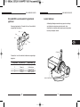
Lensin takilmasi
Sekildeki gibi bilezigin üzerindeki vidayi gevsetin ve bilezigi
saat yönünün tersine duruncaya kadar çevirin. Imaj
Sensörünün lens takilirken darbe almamasina özen gösterin
bu arizaya sebebiyet verebilir.
C Direction
Auto Iris Control Cable
Otomatik IRIS Lens Konnektör baglantisinin
yapilmasi
Kameraya baglamak için Otomatik Iris Lens Konnektörünü
asagidaki gibi hazirlayiniz.
Otomatik Iris Lens Konnektörünü kablolarini asagidaki gibi
baglayiniz.
Pin Numarasi DC Kontrol Tipi Video Kontrol Tipi
1 Damp (-) Güç Kaynagi (+9V)
2 Damp (+) Kullanilmiyor
3 Drive (+) Video Sinyali
4 Drive (-) GND (Toprak)
KULLANIM KLAVUZU
6
Rib
Pin1
Pin2
Pin3
Pin4
Sayfa yükleniyor...
Sayfa yükleniyor...
Sayfa yükleniyor...
Sayfa yükleniyor...
Sayfa yükleniyor...
Sayfa yükleniyor...
Sayfa yükleniyor...
Sayfa yükleniyor...
Sayfa yükleniyor...
-
 1
1
-
 2
2
-
 3
3
-
 4
4
-
 5
5
-
 6
6
-
 7
7
-
 8
8
-
 9
9
-
 10
10
-
 11
11
-
 12
12
-
 13
13
-
 14
14
-
 15
15
-
 16
16
-
 17
17
-
 18
18
-
 19
19
-
 20
20
-
 21
21
-
 22
22
-
 23
23
-
 24
24
-
 25
25
-
 26
26
-
 27
27
-
 28
28
-
 29
29


Samsung SCC-101BP Kullanım kılavuzu
- Kategori
- Güvenlik kameraları
- Tip
- Kullanım kılavuzu
- Bu kılavuz aynı zamanda aşağıdakiler için de uygundur:
diğer dillerde
- English: Samsung SCC-101BP User manual
İlgili makaleler
-
Samsung SCC-B2003P Kullanım kılavuzu
-
-
-
-
-
-
Samsung SCC-B2313P Kullanım kılavuzu
-
-
-