Simplicity 10V332-S016-97 Kullanım kılavuzu
- Kategori
- Motorlu taşıt aksesuarları
- Tip
- Kullanım kılavuzu
Bu kılavuz için de uygundur

Not for
Reproduction
Copyright © Briggs & Stratton Corporation
Milwaukee, WI, USA. All rights reserved.
80081994
Revision: A


Not for
Reproduction
3
6 7
8
9
10
11
12


Not for
Reproduction
5
22

Not for
Reproduction
6 VanguardEngines.com
Copyright © Briggs & Stratton Corporation, Milwaukee, WI, USA. All rights reserved.
This manual contains safety information to make you aware of the hazards and risks
associated with engines and how to avoid them. It also contains instructions for the
proper use and care of the engine. Because Briggs & Stratton Corporation does not
necessarily know what equipment this engine will power, it is important that you read
and understand these instructions and the instructions for the equipment.Save these
original instructions for future reference.
Note:The figures and illustrations in this manual are provided for reference only and
may differ from your specific model. Contact your dealer if you have questions.
For replacement parts or technical assistance, record below the engine model, type,
and code numbers along with the date of purchase. These numbers are located on your
engine (see theFeatures and Controlssection).
Date of Purchase
Engine Model - Type - Trim
Engine Serial Number
European Office Contact
Information
For questions regarding European emissions, please contact our European office at:
Max-Born-Straße 2, 68519 Viernheim, Germany.
European Union (EU) Stage
V (5): Carbon Dioxide (CO
2
)
Values
Carbon dioxide values of Briggs & Stratton EU Type-Approval Certificate engines can be
found by entering CO2 into the search window on BriggsandStratton.com.
Recycling Information
Recycle all packaging, used oil, and batteries according to
applicable government regulations.
Operator Safety
Safety Alert Symbol and Signal Words
The safety alert symbol ( ) is used to identify safety information about hazards that
can result in personal injury. A signal word (DANGER, WARNING, or CAUTION) is used
with the alert symbol to indicate the likelihood and the potential severity of injury. In
addition, a hazard symbol may be used to represent the type of hazard.
DANGERindicates a hazard which, if not avoided,will result in death or
serious injury.
WARNINGindicates a hazard which, if not avoided,could result in death or
serious injury.
CAUTIONindicates a hazard which, if not avoided,could result in minor or
moderate injury.
NOTICEindicates a situation thatcould result in damage to the product.
Hazard Symbols and Meanings
Safety information about
hazards that can result in
personal injury.
Read and understand the
Operator's Manual before
operating or servicing the
unit.
Fire hazard Explosion hazard
Shock hazard Toxic fume hazard
Hot surface hazard Noise hazard - Ear protection
recommended for extended
use.
Thrown object hazard -
Wear eye protection.
Explosion hazard
Frostbite hazard Kickback hazard
Amputation hazard -
moving parts
Chemical hazard
Thermal heat hazard Corrosive
Safety Messages
WARNING
Briggs & Stratton® Engines are not designed for and are not to be used to power:
fun-karts; go-karts; children's, recreational, or sport all-terrain vehicles (ATVs);
motorbikes; hovercraft; aircraft products; or vehicles used in competitive events not
sanctioned by Briggs & Stratton. For information about competitive racing products,
see www.briggsracing.com. For use with utility and side-by-side ATVs, please contact
Briggs & Stratton Power Application Center, 1-866-927-3349. Improper engine
application may result in serious injury or death.
WARNING
Fuel and its vapors are extremely flammable and explosive.
Fire or explosion can cause severe burns or death.
When Adding Fuel
• Turn engine off and let engine cool at least 2 minutes before removing the fuel
cap.
• Fill fuel tank outdoors or in well-ventilated area.
• Do not overfill fuel tank. To allow for expansion of the fuel, do not fill above the
bottom of the fuel tank neck.
• Keep fuel away from sparks, open flames, pilot lights, heat, and other ignition
sources.
• Check fuel lines, tank, cap, and fittings frequently for cracks or leaks. Replace if
necessary.
• If fuel spills, wait until it evaporates before starting engine.
When Starting Engine
• Make sure that spark plug, muffler, fuel cap and air cleaner (if equipped) are in
place and secured.
• Do not crank engine with spark plug removed.
• If engine floods, set choke (if equipped) to OPEN / RUN position, move throttle (if
equipped) to FAST position and crank until engine starts.
When Operating Equipment
• Do not tip engine or equipment at angle which causes fuel to spill.

Not for
Reproduction
7
• Do not choke the carburetor to stop engine.
• Never start or run the engine with the air cleaner assembly (if equipped) or the air
filter (if equipped) removed.
When Changing Oil
• If you drain the oil from the top oil fill tube, the fuel tank must be empty or fuel can
leak out and result in a fire or explosion.
When Tipping Unit for Maintenance
• When performing maintenance that requires the unit to be tipped, the fuel tank, if
mounted on the engine, must be empty or fuel can leak out and result in a fire or
explosion.
When Transporting Equipment
• Transport with fuel tank EMPTY or with fuel shut-off valve in the CLOSED
position.
When Storing Fuel Or Equipment With Fuel In Tank
• Store away from furnaces, stoves, water heaters or other appliances that have
pilot lights or other ignition sources because they can ignite fuel vapors.
WARNING
Starting engine creates sparking.
Sparking can ignite nearby flammable gases.
Explosion and fire could result.
• If there is natural or LP gas leakage in area, do not start engine.
• Do not use pressurized starting fluids because vapors are flammable.
WARNING
POISONOUS GAS HAZARD. Engine exhaust contains carbon monoxide, a
poisonous gas that could kill you in minutes. You CANNOT see it, smell it, or
taste it. Even if you do not smell exhaust fumes, you could still be exposed
to carbon monoxide gas. If you start to feel sick, dizzy, or weak while using
this product, get to fresh air RIGHT AWAY. See a doctor. You may have carbon
monoxide poisoning.
• Operate this product ONLY outside far away from windows, doors and vents to
reduce the risk of carbon monoxide gas from accumulating and potentially being
drawn towards occupied spaces.
• Install battery-operated carbon monoxide alarms or plug-in carbon monoxide
alarms with battery back-up according to the manufacturer's instructions. Smoke
alarms cannot detect carbon monoxide gas.
• DO NOT run this product inside homes, garages, basements, crawlspaces,
sheds, or other partially-enclosed spaces even if using fans or opening doors and
windows for ventilation. Carbon monoxide can quickly build up in these spaces
and can linger for hours, even after this product has shut off.
• ALWAYS place this product downwind and point the engine exhaust away from
occupied spaces.
WARNING
Rapid retraction of starter cord (kickback) will pull hand and arm toward engine
faster than you can let go.
Broken bones, fractures, bruises or sprains could result.
• When starting engine, pull the starter cord slowly until resistance is felt and then
pull rapidly to avoid kickback.
• Remove all external equipment / engine loads before starting engine.
• Direct-coupled equipment components such as, but not limited to, blades,
impellers, pulleys, sprockets, etc., must be securely attached.
WARNING
Rotating parts can contact or entangle hands, feet, hair, clothing, or
accessories.
Traumatic amputation or severe laceration can result.
• Operate equipment with guards in place.
• Keep hands and feet away from rotating parts.
• Tie up long hair and remove jewelry.
• Do not wear loose-fitting clothing, dangling drawstrings or items that could become
caught.
WARNING
Running engines produce heat. Engine parts, especially muffler, become
extremely hot.
Severe thermal burns can occur on contact.
Combustible debris, such as leaves, grass, brush, etc. can catch fire.
• Allow muffler, engine cylinder and fins to cool before touching.
• Remove accumulated debris from muffler area and cylinder area.
• It is a violation of California Public Resource Code, Section 4442, to use or
operate the engine on any forest-covered, brush-covered, or grass-covered land
unless the exhaust system is equipped with a spark arrester, as defined in Section
4442, maintained in effective working order. Other states or federal jurisdictions
may have similar laws. Contact the original equipment manufacturer, retailer, or
dealer to obtain a spark arrester designed for the exhaust system installed on this
engine.
WARNING
Unintentional sparking can result in fire or electric shock.
Unintentional start-up can result in entanglement, traumatic amputation, or
laceration.
Fire hazard
Before performing adjustments or repairs:
• Disconnect the spark plug wire and keep it away from the spark plug.
• Disconnect battery at negative terminal (only engines with electric start.)
• Use only correct tools.
• Do not tamper with governor spring, links or other parts to increase engine speed.
• Replacement parts must be of the same design and installed in the same position
as the original parts. Other parts may not perform as well, may damage the unit,
and may result in injury.
• Do not strike the flywheel with a hammer or hard object because the flywheel may
later shatter during operation.
When testing for spark:
• Use approved spark plug tester.
• Do not check for spark with spark plug removed.
Features and Controls
Engine Controls
Compare the illustration (Figure:1,2) with your engine to familiarize yourself with the
location of various features and controls.
1
A. Engine Identification NumbersModel - Type - Code
B. Spark Plug
C. Fuel Tank and Cap
D. Air Cleaner
E. Starter Cord Handle
F. Oil Dipstick
G. Oil Fill
H. Oil Drain Plug
I. Muffler, Muffler Guard (if equipped), Spark Arrester (if equipped)
J. Throttle Control / Fuel Shutoff / TransportGuard®
K. Choke Control
L. Air Intake Grille
M. Electric Start Switch (if equipped)
1
Some engines and equipment have remote controls. See the equipment
manual for location and operation of remote controls.

Not for
Reproduction
8 VanguardEngines.com
Engine Control Symbols and Meanings
Engine speed - FAST Engine speed - SLOW
Engine speed - STOP ON - OFF
Engine start - Choke
CLOSED
Engine start - Choke OPEN
Fuel Cap
Fuel Shut-off - OPEN
Fuel Shut-off - CLOSED
Fuel level - Maximum
Do not overfill
Assembly
Throttle Control Conversion
The standard engine has a manual throttle control.To operate with the manual throttle
control, to install a remote throttle control, or to convert to a fixed speed, follow the
appropriate instructions below.
Note:After installation, the engine speed may need to be adjusted to meet the
equipment manufacturer's performance specifications. Contact a Briggs & Stratton
Authorized Service Dealer for assistance.
Manual Throttle Control
See Figure:5
1. Move the throttle control / TransportGuard® lever (A, Figure5) to the OFF
position.
2. Remove the spring (S, Figure5).
Remote Throttle Control with Braided Wire Cable
A remote throttle control with a braided wire cable can be installed in either of two
directions;Cylinder Head DirectionorFront Direction.
Cylinder Head Direction
See Figure:3,5
1. Use a 10 mm wrench and loosen nut (P, Figure5) ½ turn on the throttle control /
TransportGuard® lever (A).
2. Hold the cable mounting nut (J, Figure3) with a 10 mm wrench and loosen screw
(K).
3. Install the cable wire (L, Figure3) through the hole in the cable mounting nut (J)
and tighten screw (K). Make sure that the cable wire (L) does not extend more
than ½" (12,7 mm) past the hole.
4. Loosen the screw (I, Figure3). Secure the cable sleeve (N) under the cable
clamp (M) and tighten the screw (I).
5. To check the operation of the remote throttle control, move the remote throttle
control from slow to fast a few times. The remote throttle control and the cable
wire (L, Figure3) should move freely.Adjust nut (P, Figure5) as needed for
desired operation.
Front Direction
See Figure:4,5
1. Use a 10 mm wrench and loosen nut (P, Figure5) ½ turn on the throttle control /
TransportGuard® lever (A).
2. Hold the cable mounting nut (J, Figure4) with a 10 mm wrench and loosen screw
(K).
3. Install the cable wire (L, Figure4) through the hole in the cable mounting nut (J)
and tighten screw (K). Make sure that the cable wire (L) does not extend more
than ½" (12,7 mm) past the hole.
4. Loosen the screw (I, Figure4). Secure the cable sleeve (N) under the cable
clamp (M) and tighten the screw (I).
5. To check the operation of the remote throttle control, move the remote throttle
control from slow to fast a few times. The remote throttle control and the cable
wire (L, Figure4) should move freely.Adjust nut (P, Figure5) as needed for
desired operation.
Remote Throttle Control with Solid Wire Cable
A remote throttle control with a solid wire cable can be installed is any of four
directions;Cylinder Head Direction, Front Direction, Left Direction,orRight
Direction.
Cylinder Head Direction
See Figure:5,6
1. Move the throttle control / TransportGuard® lever (A, Figure5,6) to the OFF
position.
2. Remove the spring (S, Figure5,6).
3. Use a 10 mm wrench and loosen nut (P, Figure5) ½ turn on the throttle control /
TransportGuard® lever (A).
4. Install the Z-fitting of the solid wire cable (Q, Figure6) to either one of the small
holes in the bellcrank (R).
5. Loosen the screw (I, Figure6). Secure the cable sleeve (N) under the cable
clamp (M) and tighten the screw (I).
6. To check the operation of the remote throttle control, move the remote throttle
control from slow to fast a few times. The remote throttle control and the solid
wire cable (L, Figure6) should move freely.Adjust nut (P, Figure5) as needed
for desired operation.
Front Direction
See Figure:5,7
1. Move the throttle control / TransportGuard® lever (A, Figure5,7) to the OFF
position.
2. Remove the spring (S, Figure5,7).
3. Use a 10 mm wrench and loosen nut (P, Figure5) ½ turn on the throttle control /
TransportGuard® lever (A).
4. Install the Z-fitting of the solid wire cable (Q, Figure7) to either one of the small
holes in the bellcrank (R).
5. Loosen the screw (I, Figure7). Secure the cable sleeve (N) under the cable
clamp (M) and tighten the screw (I).
6. To check the operation of the remote throttle control, move the remote throttle
control from slow to fast a few times. The remote throttle control and the solid
wire cable (L, Figure7) should move freely.Adjust nut (P, Figure5) as needed
for desired operation.
Left Direction
See Figure:5,8
1. Move the throttle control / TransportGuard® lever (A, Figure8) to the OFF
position.
2. Remove the spring (S, Figure5).
3. Use a 10 mm wrench and loosen nut (P, Figure5) ½ turn on the throttle control /
TransportGuard® lever (A).
4. Install the Z-fitting of the solid wire cable (L, Figure8) to the small hole (S) in the
throttle control lever (A).
5. Loosen the screw (I, Figure8). Secure the cable sleeve (N) under the cable
clamp (M) and tighten the screw (I).
6. To check the operation of the remote throttle control, move the remote throttle
control from slow to fast a few times. The remote throttle control and the solid
wire cable (L, Figure8) should move freely.Adjust nut (P, Figure5) as needed
for desired operation.
Right Direction
See Figure:5,9
To install a remote throttle control from the right direction, a cable mounting bracket (U,
Figure9, part number84004150) is required. To purchase a cable mounting bracket,
contact a Briggs & Stratton Authorized Service Dealer.
1. Move the throttle control / TransportGuard® lever (A, Figure5,9) to the OFF
position.
2. Remove the spring (S, Figure5).
3. Use a 10 mm wrench and loosen nut (P, Figure5) ½ turn on the throttle control /
TransportGuard® lever (A).
4. Install the Z-fitting of the solid wire cable (L, Figure9) to the small hole (S) in the
throttle control lever (A).
5. Remove the bolt (T, Figure9). Install the cable mounting bracket (U) to the
location as shown in Figure9. Secure the cable mounting bracket (U) with the
bolt (T). Tighten the bolt (T) to 30 lb-in (3,4 Nm).

Not for
Reproduction
9
6. Loosen the screw (I, Figure9). Secure the cable sleeve (N) under the cable
clamp (M) and tighten the screw (I).
7. To check the operation of the remote throttle control, move the remote throttle
control from slow to fast a few times. The remote throttle control and the solid
wire cable (L, Figure9) should move freely.Adjust nut (P, Figure5) as needed
for desired operation.
Fixed Engine Speed (No Throttle Control Cable)
See Figure:10,11
When converted to aFixed Engine Speed, there is no throttle control cable and no
speed selection. Fast is the only engine speed.
1. Move the throttle control / TransportGuard® lever (A, Figure10) to the OFF
position.
2. Remove the spring (S, Figure10).
3. Move the throttle control / TransportGuard® lever (A, Figure10) to the FAST
position.
4. Make sure the screw (V, Figure10) is aligned with the hole in the bracket.
Tighten screw (V) to 25 lb-in (2,8 Nm).
5. Remove the control link (H, Figure10).
Note:The throttle control / TransportGuard® lever will now only have two positions:
STOP / OFF position and RUN position.
6. Install the new ON / OFF TransportGuard® label (O, Figure11) over the existing
speed control label located on the trim panel (F).
Operation
Oil Recommendations
Oil Capacity:See theSpecificationssection.
NOTICE
This engine was shipped from Briggs & Stratton without oil. Equipment manufacturers
or dealers may have added oil to the engine. Before you start the engine for the first
time, make sure to check the oil level and add oil as specified by the instructions in
this manual. If you start the engine without oil, it will be damaged beyond repair and
will not be covered under warranty.
We recommend the use of Briggs & Stratton
®
Warranty Certified oils for best
performance. Other high-quality detergent oils are permitted if classified for service SF,
SG, SH, SJ or higher. Do not use special additives.
Outdoor temperatures determine the correct oil viscosity for the engine. Use the chart
to select the best viscosity for the outdoor temperature range expected. Engines on
most outdoor power equipment operate well with 5W-30 Synthetic oil. For equipment
operated in hot temperatures, Vanguard
®
15W-50 Synthetic oil gives the best
protection.
A SAE 30 -Below 40 °F (4 °C) the use of SAE 30 will result in hard starting.
B 10W-30 -Above 80 °F (27 °C) the use of 10W-30 may cause increased oil
consumption. Checkthe oil level frequently.
C 5W-30
D Synthetic 5W-30
E
Vanguard
®
Synthetic 15W-50
Check Oil Level
See Figure: 12, 13
Before adding or checking the oil
• Make sure the engine is level.
• Clean the oil fill area of any debris.
• See the Specifications section for oil capacity.
NOTICE This engine was shipped from Briggs & Stratton without oil. Equipment
manufacturers or dealers may have added oil to the engine. Before you start the
engine for the first time, make sure to check the oil level and add oil according to
the instructions in this manual. If you start the engine without oil, it will be damaged
beyond repair and will not be covered under warranty.
1. Remove the dipstick (A, Figure 12) and wipe with a clean cloth.
2. Install the dipstick (A, Figure 12).
3. Remove the dipstick and check the oil level. Correct oil level is at the top of the full
indicator (B, Figure 12) on the dipstick.
4. The engine has multiple oil fills (C, G, Figure 13). If the oil level is low, slowly add
oil into one of the engine oil fills (C, G). Do not overfill. After adding oil, wait one
minute and then check the oil level.
5. Reinstall the dipstick (A, Figure 12).
Low Oil Protection System (if equipped)
Some engines are equipped with a low oil sensor. If the oil is low, the sensor will either
activate a warning light or stop the engine. Stop the engine and follow these steps
before restarting the engine.
• Make sure the engine is level.
• Check the oil level. See the Check Oil Level section.
• If the oil level is low, add the proper amount of oil. Start the engine and make sure
the warning light (if equipped) is not activated.
• If the oil level is not low, do not start the engine. Contact a Briggs & Stratton
Authorized Service Dealer to have the oil problem corrected.
Fuel Recommendations
Fuel must meet these requirements:
• Clean, fresh, unleaded gasoline.
• A minimum of 87 octane/87 AKI (91 RON). High altitude use, see below.
• Gasoline with up to 10% ethanol (gasohol) is acceptable.
NOTICE Do not use unapproved gasolines, such as E15 and E85. Do not mix oil in
gasoline or modify the engine to run on alternate fuels. Use of unapproved fuels will
damage the engine components, which will not be covered under warranty.
To protect the fuel system from gum formation, mix a fuel stabilizer into the fuel.
SeeStorage.All fuel is not the same. If start or performance problems occur, change
fuel providers or brands. This engine is certified to operate on gasoline. The emissions
control system for carbureted engines is EM (Engine Modifications). The emissions
control systems for engines with electronic fuel injection are ECM (Engine Control
Module), MPI (Multi Port Injection), and if equipped an O2S (Oxygen Sensor).
High Altitude
At altitudes over 5,000 feet (1524 meters), a minimum 85 octane/85 AKI (89 RON)
gasoline is acceptable.
For carbureted engines, high altitude adjustment is required to maintain performance.
Operation without this adjustment will cause decreased performance, increased fuel
consumption, and increased emissions. Contact a Briggs & Stratton Authorized Service
Dealer for high altitude adjustment information. Operation of the engine at altitudes
below 2,500 feet (762 meters) with the high altitude adjustment is not recommended.
For Electronic Fuel Injection (EFI) engines, no high altitude adjustment is necessary.
Add Fuel
WARNING
Fuel and its vapors are extremely flammable and explosive.
Fire or explosion can cause severe burns or death.
When adding fuel
• Turn engine off and let engine cool at least 2 minutes before removing the fuel
cap.
• Fill fuel tank outdoors or in well-ventilated area.
• Do not overfill fuel tank. To allow for expansion of the fuel, do not fill above the
bottom of the fuel tank neck.
• Keep fuel away from sparks, open flames, pilot lights, heat, and other ignition
sources.
• Check fuel lines, tank, cap, and fittings frequently for cracks or leaks. Replace if
necessary.
• If fuel spills, wait until it evaporates before starting engine.

Not for
Reproduction
10 VanguardEngines.com
1. Clean the fuel cap area of dirt and debris. Remove the fuel cap.
2. Fill the fuel tank (A, Figure14) with fuel. To allow for expansion of the fuel, do not
fill above the bottom of the fuel tank neck (B).
3. Install the fuel cap.
Start and Stop Engine
See Figure:15
Start Engine
WARNING
Rapid retraction of starter cord (kickback) will pull hand and arm toward
engine faster than you can let go.
Broken bones, fractures, bruises or sprains could result.
• When starting engine, pull the starter cord slowly until resistance is felt and then
pull rapidly to avoid kickback.
WARNING
Fuel and its vapors are extremely flammable and explosive.
Fire or explosion can cause severe burns or death.
When Starting Engine
• Ensure that spark plug, muffler, fuel cap and air cleaner (if equipped) are in place
and secured.
• Do not crank engine with spark plug removed.
• If engine floods, set choke (if equipped) to OPEN or RUN position, move throttle
(if equipped) to FAST position and crank until engine starts.
WARNING
POISONOUS GAS HAZARD. Engine exhaust contains carbon monoxide, a
poisonous gas that could kill you in minutes. You CANNOT see it, smell it, or
taste it. Even if you do not smell exhaust fumes, you could still be exposed to
carbon monoxide gas. If you start to feel sick, dizzy, or weak while using this
product, shut it off and get to fresh air RIGHT AWAY. See a doctor. You may
have carbon monoxide poisoning.
• Operate this product ONLY outside far away from windows, doors and vents to
reduce the risk of carbon monoxide gas from accumulating and potentially being
drawn towards occupied spaces.
• Install battery-operated carbon monoxide alarms or plug-in carbon monoxide
alarms with battery back-up according to the manufacturer's instructions. Smoke
alarms cannot detect carbon monoxide gas.
• DO NOT run this product inside homes, garages, basements, crawlspaces,
sheds, or other partially-enclosed spaces even if using fans or opening doors and
windows for ventilation. Carbon monoxide can quickly build up in these spaces
and can linger for hours, even after this product has shut off.
• ALWAYS place this product downwind and point the engine exhaust away from
occupied spaces.
NOTICE This engine was shipped from Briggs & Stratton without oil. Before you
start the engine, make sure you add oil according to the instructions in this manual.
If you start the engine without oil, it will be damaged beyond repair and will not be
covered under warranty.
Note:Equipment may have remote controls. See the equipment manual for location
and operation of remote controls.
1. Check the engine oil. See theCheck Oil Levelsection.
2. Make sure equipment drive controls, if equipped, are disengaged.
3. Move the throttle control / TransportGuard® (A, Figure15) to the FAST or RUN
position. Operate the engine in the FAST or RUN position.
4. Move the choke control (B, Figure15) to the CLOSED position.
Note:Choke is usually unnecessary when restarting a warm engine.
5. Rewind Start, if equipped:Firmly hold the starter cord handle (C, Figure15).
Pull the starter cord handle slowly until resistance is felt, then pull rapidly.
WARNING
Rapid retraction of the starter cord (kickback) will pull your hand and arm toward the
engine faster than you can let go. Broken bones, fractures, bruises or sprains could
result. When starting engine, pull the starter cord slowly until resistance is felt and
then pull rapidly to avoid kickback.
6. Electric Start, if equipped:Turn the electric start switch (D, Figure15) to the
START position.
NOTICE To extend the life of the starter, use short starting cycles (five seconds
maximum). Wait one minute between starting cycles.
7. As the engine warms up, move the choke control (B, Figure15) to the OPEN
position.
Note:If the engine does not start after repeated attempts, contact a local dealer or go
toVanguardEngines.comor call1-800-999-9333(in USA).
Stop Engine
WARNING
Fuel and its vapors are extremely flammable and explosive.
Fire or explosion can cause severe burns or death.
• Do not choke the carburetor to stop the engine.
Throttle Control / TransportGuard®:Move the throttle control / TransportGuard® (A,
Figure15) to the OFF or STOP position.
Note:When the throttle control / TransportGuard® is in the OFF or STOP position, the
fuel valve is in the OFF position. Always move the throttle control / TransportGuard® to
the OFF or STOP position when transporting equipment.
Note:The key (D, Figure15) does not stop the engine, the key only starts the engine. To
keep children from starting the engine, always remove the key (D) when not in use.
Maintenance
NOTICE If the engine is tipped during maintenance, the fuel tank, if mounted on
engine, must be empty and the spark plug side must be up. If the fuel tank is not
empty and if the engine is tipped in any other direction, it may be difficult to start due
to oil or gasoline contaminating the air filter and/or the spark plug.
WARNING
When performing maintenance that requires the unit to be tipped, the fuel tank, if
mounted on the engine, must be empty or fuel can leak out and result in a fire or
explosion.
We recommend that you see any Briggs & Stratton Authorized Service Dealer for all
maintenance and service of the engine and engine parts.
NOTICE All the components used to build this engine must remain in place for
proper operation.
WARNING
Unintentional sparking can result in fire or electric shock.
Unintentional start-up can result in entanglement, traumatic amputation, or
laceration.
Fire hazard
Before performing adjustments or repairs:
• Disconnect the spark plug wire and keep it away from the spark plug.
• Disconnect battery at negative terminal (only engines with electric start).
• Use only correct tools.
• Do not tamper with governor spring, links or other parts to increase engine speed.
• Replacement parts must be of the same design and installed in the same position
as the original parts. Other parts may not perform as well, may damage the unit,
and may result in injury.
• Do not strike the flywheel with a hammer or hard object because the flywheel may
later shatter during operation.
When testing for spark:
• Use approved spark plug tester.
• Do not check for spark with spark plug removed.
Emissions Control Service
Maintenance, replacement, or repair of the emissions control devices and
systems may be performed by any off-road engine repair establishment or
individual. However, to obtain "no charge" emissions control service, the work must be
performed by a factory authorized dealer. See the Emissions Control Statements.

Not for
Reproduction
11
Maintenance Schedule
First 5 Hours
• Change oil
Every 8 Hours or Daily
• Check engine oil level
• Clean area around muffler and controls
• Clean air intake grille
Every 100 Hours or Annually
• Service exhaust system
Every 200 Hours or Annually
• Change engine oil
•
Clean air filter
1
Every 600 Hours or Every 3 Years
• Replace air filter
Annually
• Replace spark plug
• Service fuel system
•
Service cooling system
1
•
Check valve clearance
2
1
In dusty conditions or when airborne debris is present, clean more often.
2
Not required unless engine performance problems are noted.
Carburetor and Engine Speed
Never make adjustments to the carburetor or engine speed. The carburetor was set at
the factory to operate efficiently under most conditions. Do not tamper with the governor
spring, linkages, or other parts to change the engine speed. If any adjustments are
required contact a Briggs & Stratton Authorized Service Dealer for service.
NOTICE The equipment manufacturer specifies the maximum speed for the engine
as installed on the equipment.Do not exceedthis speed. If you are not sure what the
equipment maximum speed is, or what the engine speed is set to from the factory,
contact a Briggs & Stratton Authorized Service Dealer for assistance. For safe and
proper operation of the equipment, the engine speed should be adjusted only by a
qualified service technician.
Service Spark Plug
See Figure:16
Check the gap (A, Figure16) with a wire gauge (B). If necessary, reset the gap. Install
and tighten the spark plug to the recommended torque. For gap setting or torque, see
theSpecificationssection.
Note:In some areas, local law requires using a resistor spark plug to suppress ignition
signals. If this engine was originally equipped with a resistor spark plug, use the same
type for replacement.
Service Exhaust System
WARNING
Running engines produce heat. Engine parts, especially muffler, become
extremely hot.
Severe thermal burns can occur on contact.
Combustible debris, such as leaves, grass, brush, etc. can catch fire.
• Allow muffler, engine cylinder and fins to cool before touching.
• Remove accumulated debris from muffler area and cylinder area.
• It is a violation of California Public Resource Code, Section 4442, to use or
operate the engine on any forest-covered, brush-covered, or grass-covered land
unless the exhaust system is equipped with a spark arrester, as defined in Section
4442, maintained in effective working order. Other states or federal jurisdictions
may have similar laws. Contact the original equipment manufacturer, retailer, or
dealer to obtain a spark arrester designed for the exhaust system installed on this
engine.
Remove accumulated debris from muffler and cylinder area. Inspect the muffler for
cracks, corrosion, or other damage. Remove the deflector or the spark arrester, if
equipped, and inspect for damage or carbon blockage. If damage is found, install
replacement parts before operating.
WARNING
Replacement parts must be of the same design and installed in the same position
as the original parts. Other parts may not perform as well, may damage the unit, and
may result in injury.
Change Engine Oil
See Figure: 17, 18, 19
Used oil is a hazardous waste product and must be disposed of properly. Do not discard
with household waste. Check with your local authorities, service center, or dealer for
safe disposal/recycling facilities.
Remove Oil
1. With engine off but still warm, disconnect the spark plug wire (D, Figure 17) and
keep it away from the spark plug (E).
2. Remove the dipstick (A, Figure 18).
3. The engine has two oil drain plugs. Remove one of the oil drain plugs (F, H,
Figure 19). Drain the oil into an approved container.
4. After the oil has drained, install and tighten the oil drain plug (F, H, Figure 19).
Add Oil
• Make sure the engine is level.
• Clean the oil fill area of any debris.
• See the Specifications section for oil capacity.
1. Remove the dipstick (A, Figure 18) and wipe with a clean cloth.
2. The engine has multiple oil fills. Slowly pour oil into one of the engine oil fills (C,
G, Figure 19). Do not overfill. After adding oil, wait one minute and then check
the oil level.
3. Install the dipstick (A, Figure 18).
4. Remove the dipstick and check the oil level. Correct oil level is at the top of the
full indicator (B, Figure 18) on the dipstick.
5. Reinstall the dipstick (A, Figure 18).
6. Connect the spark plug wire (D, Figure 17) to the spark plug (E).
Service Air Filter
See Figure: 20
WARNING
Fuel and its vapors are extremely flammable and explosive.
Fire or explosion can cause severe burns or death.
• Never start and run the engine with the air cleaner assembly (if equipped) or the
air filter (if equipped) removed.
NOTICE Do not use pressurized air or solvents to clean the filter. Pressurized air
can damage the filter and solvents will dissolve the filter.
See the Maintenance Schedule for service requirements.
Paper Air Filter
1. Loosen the fastener(s) (C, Figure 20).
2. Remove the cover (A, Figure 20).
3. Remove the filter (B, Figure 20).
4. To loosen debris, gently tap the filter (B, Figure 20) on a hard surface. If the filter is
excessively dirty, replace with a new filter.
5. Install the filter (B, Figure 20) .
6. Install the cover (A, Figure 20) and secure with the fastener(s) (C). Make sure the
fastener(s) is tight.
Service Fuel System
See Figure: 21
WARNING
Fuel and its vapors are extremely flammable and explosive.
Fire or explosion can cause severe burns or death.

Not for
Reproduction
12 VanguardEngines.com
• Keep fuel away from sparks, open flames, pilot lights, heat, and other ignition
sources.
• Check fuel lines, tank, cap, and fittings frequently for cracks or leaks. Replace if
necessary.
• Before cleaning or replacing the fuel filter, drain the fuel tank or close the fuel shut-
off valve.
• If fuel spills, wait until it evaporates before starting engine.
• Replacement parts must be the same and installed in the same position as the
original parts.
Fuel Strainer, if equipped
1. Remove the fuel cap (A, Figure 21).
2. Remove the fuel strainer (B, Figure 21).
3. If the fuel strainer is dirty, clean or replace it. If you replace the fuel strainer, make
sure to use an original equipment replacement fuel strainer.
Service Cooling System
WARNING
Running engines produce heat. Engine parts, especially muffler, become
extremely hot.
Severe thermal burns can occur on contact.
Combustible debris, such as leaves, grass, brush, etc., can catch fire.
• Allow muffler, engine cylinder and fins to cool before touching.
• Remove accumulated debris from muffler area and cylinder area.
NOTICE Do not use water to clean the engine. Water could contaminate the fuel
system. Use a brush or dry cloth to clean the engine.
This is an air cooled engine. Dirt or debris can restrict air flow and cause the engine to
overheat, resulting in poor performance and reduced engine life.
1. Use a brush or dry cloth to remove debris from the air intake grille.
2. Keep linkage, springs and controls clean.
3. Keep the area around and behind the muffler, if equipped, free of any combustible
debris.
4. Make sure the oil cooler fins, if equipped, are free of dirt and debris.
After a period of time, debris can accumulate in the cylinder cooling fins and cause the
engine to overheat. This debris cannot be removed without partial disassembly of the
engine. Have a Briggs & Stratton Authorized Service Dealer inspect and clean the air
cooling system as recommended in the Maintenance Schedule.
Storage
WARNING
Fuel and its vapors are extremely flammable and explosive.
Fire or explosion can cause severe burns or death.
When Storing Fuel Or Equipment With Fuel In Tank
• Store away from furnaces, stoves, water heaters or other appliances that have
pilot lights or other ignition sources because they can ignite fuel vapors.
Fuel System
See Figure:22
Store the engine level (normal operating position). Fill fuel tank (A, Figure22) with fuel.
To allow for expansion of fuel, do not overfill above the fuel tank neck (B).
Fuel can become stale when kept in a storage container for more than 30 days. Each
time you fill the container with fuel, addfuel stabilizerto the fuel as specified by the
manufacturer’s instructions. This keeps fuel fresh and decreases fuel-related problems
or contamination in the fuel system.
It is not necessary to drain fuel from the engine whenfuel stabilizeris added as
instructed. Before storage, turn the engine ON for 2 minutes to move the fuel and
stabilizer through the fuel system.
If gasoline in the engine has not been treated with a fuel stabilizer, it must be drained
into an approved container. Run the engine until it stops from lack of fuel. The use of a
fuel stabilizer in the storage container is recommended to maintain freshness.
Engine Oil
While the engine is still warm, change the engine oil. See the Change Engine Oil
section.
Troubleshooting
For assistance, contact your local dealer or go to VanguardEngines.com or call
1-800-999-9333 (in USA).
Specifications
Model:25V000
Displacement 24.898ci (408cc)
Bore 3.465in (88mm)
Stroke 2.638in (67mm)
Oil Capacity 28 - 32oz (,82 - ,95L)
Spark Plug Gap .030in (,76mm)
Spark Plug Torque 170lb-in (19.2Nm)
Armature Air Gap .010 - .014in (,25 - ,35mm)
Intake Valve Clearance .004 - .006in (,10 - ,15mm)
Exhaust Valve Clearance .006 - .008in (,15 - ,20mm)
Engine power will decrease 3.5% for each 1,000 feet (300 meters) above sea level and
1% for each 10° F (5.6° C) above 77° F (25° C). The engine will operate satisfactorily
at an angle up to 30°. Refer to the equipment operator's manual for safe allowable
operating limits on slopes.
Service Parts - Model:25V000
Service Part Part Number
Paper Air Filter (Figure20) 84002310
Resistor Spark Plug 597383
Spark Plug Wrench 19576, 5402
Spark Tester 19368
We recommend that you see any Briggs & Stratton Authorized Dealer for all
maintenance and service of the engine and engine parts.
Power Ratings:The gross power rating for individual gasoline engine models is
labeled in accordance with SAE (Society of Automotive Engineers) code J1940 Small
Engine Power & Torque Rating Procedure, and is rated in accordance with SAE J1995.
Torque values are derived at 2600 RPM for those engines with “rpm” called out on the
label and 3060 RPM for all others; horsepower values are derived at 3600 RPM. The
gross power curves can be viewed at www.BRIGGSandSTRATTON.COM. Net power
values are taken with exhaust and air cleaner installed whereas gross power values
are collected without these attachments. Actual gross engine power will be higher than
net engine power and is affected by, among other things, ambient operating conditions
and engine-to-engine variability. Given the wide array of products on which engines
are placed, the gasoline engine may not develop the rated gross power when used in a
given piece of power equipment. This difference is due to a variety of factors including,
but not limited to, the variety of engine components (air cleaner, exhaust, charging,
cooling, carburetor, fuel pump, etc.), application limitations, ambient operating conditions
(temperature, humidity, altitude), and engine-to-engine variability. Due to manufacturing
and capacity limitations, Briggs & Stratton may substitute an engine of higher rated
power for this engine.
Warranty
Briggs & Stratton Engine Warranty
Effective January 2019
Limited Warranty
Briggs & Stratton warrants that, during the warranty period specified below, it will repair
or replace, free of charge, any part that is defective in material or workmanship or
both. Transportation charges on product submitted for repair or replacement under this
warranty must be borne by purchaser. This warranty is effective for and is subject to
the time periods and conditions stated below. For warranty service, find the nearest
Authorized Service Dealer in our dealer locator map at BRIGGSandSTRATTON.COM.
The purchaser must contact the Authorized Service Dealer, and then make the product
available to the Authorized Service Dealer for inspection and testing.
There is no other express warranty. Implied warranties, including those of
merchantability and fitness for a particular purpose, are limited to the warranty
period listed below, or to the extent permitted by law.Liability for incidental or

Not for
Reproduction
13
consequential damages are excluded to the extent exclusion is permitted by law. Some
states or countries do not allow limitations on how long an implied warranty lasts,
and some states or countries do not allow the exclusion or limitation of incidental or
consequential damages, so the above limitation and exclusion may not apply to you.
This warranty gives you specific legal rights and you may also have other rights which
vary from state to state and country to country
4
.
Standard Warranty Terms
1, 2, 3
Vanguard®; Commercial Series
3
Consumer Use - 36 months
Commercial Use - 36 months
XR Series
Consumer Use - 24 months
Commercial Use - 24 months
All Other Engines Featuring Dura-Bore™ Cast Iron Sleeve
Consumer Use - 24 months
Commercial Use - 12 months
All Other Engines
Consumer Use - 24 months
Commercial Use - 3 months
1
These are our standard warranty terms, but occasionally there may
be additional warranty coverage that was not determined at time of
publication. For a listing of current warranty terms for your engine, go to
BRIGGSandSTRATTON.com or contact your Briggs & Stratton Authorized Service
Dealer.
2
There is no warranty for engines on equipment used for prime power in place
of a utility; standby generators used for commercial purposes, utility vehicles
exceeding 25 MPH, or engines used in competitive racing or on commercial or
rental tracks.
3
Vanguard installed on standby generators: 24 months consumer use, no
warranty commercial use. Commercial Series with manufacturing date before July
2017: 24 months consumer use, 24 months commercial use.
4
In Australia - Our goods come with guarantees that cannot be excluded under
the Australian Consumer Law. You are entitled to a replacement or refund for a
major failure and for compensation for any other reasonably foreseeable loss or
damage. You are also entitled to have the goods repaired or replaced if the goods
fail to be of acceptable quality and the failure does not amount to a major failure.
For warranty service, find the nearest Authorized Service Dealer in our dealer
locator map at BRIGGSandSTRATTON.COM, or by calling 1300 274 447, or by
emailing or writing to [email protected], Briggs & Stratton
Australia Pty Ltd, 1 Moorebank Avenue, Moorebank, NSW , Australia, 2170.
The warranty period begins on the original date of purchase by the first retail or
commercial consumer. "Consumer use" means personal residential household use by a
retail consumer. "Commercial use" means all other uses, including use for commercial,
income producing or rental purposes. Once an engine has experienced commercial
use, it shall thereafter be considered as a commercial use engine for purposes of this
warranty.
Save your proof of purchase receipt. If you do not provide proof of the initial
purchase date at the time warranty service is requested, the manufacturing date
of the product will be used to determine the warranty period. Product registration
is not required to obtain warranty service on Briggs & Stratton products.
About Your Warranty
This limited warranty covers engine-related material and/or workmanship issues only,
and not replacement or refund of the equipment to which the engine may be mounted.
Routine maintenance, tune-ups, adjustments, or normal wear and tear are not covered
under this warranty. Similarly, warranty is not applicable if the engine has been altered
or modified or if the engine serial number has been defaced or removed. This warranty
does not cover engine damage or performance problems caused by:
1. The use of parts that are not original Briggs & Stratton parts;
2. Operating the engine with insufficient, contaminated, or an incorrect grade of
lubricating oil;
3. The use of contaminated or stale fuel, gasoline formulated with ethanol greater
than 10%, or the use of alternative fuels such as liquefied petroleum or natural gas
on engines not originally designed/manufactured by Briggs & Stratton to operate
on such fuels;
4. Dirt which entered the engine because of improper air cleaner maintenance or re-
assembly;
5. Striking an object with the cutter blade of a rotary lawn mower, loose or improperly
installed blade adapters, impellers, or other crankshaft coupled devices, or
excessive v-belt tightness;
6. Associated parts or assemblies such as clutches, transmissions, equipment
controls, etc., which are not supplied by Briggs & Stratton;
7. Overheating due to grass clippings, dirt and debris, or rodent nests which plug or
clog the cooling fins or flywheel area, or by operating the engine without sufficient
ventilation;
8. Excessive vibration due to over-speeding, loose engine mounting, loose or
unbalanced cutter blades or impellers, or improper coupling of equipment
components to the crankshaft;
9. Misuse, lack of routine maintenance, shipping, handling, or warehousing of
equipment, or improper engine installation.
Warranty service is available only through Briggs & Stratton Authorized Service
Dealers. Locate your nearest Authorized Service Dealer in our dealer locator map
at BRIGGSandSTRATTON.COM or by calling 1-800-233-3723 (in USA).
80004537 (Rev. F)
Briggs & Stratton Emissions Warranty
California, U.S. EPA, and Briggs & Stratton Corporation Emissions Control
Warranty - Your Warranty Rights and Obligations
For Briggs & Stratton Engine Models with "F" Trim Designation (Model-Type-
Trim Representation xxxxxx xxxx Fx)
The California Air Resources Board, U.S. EPA, and Briggs & Stratton (B&S) are
pleased to explain the exhaust and evaporative emissions (“emissions”) control system
warranty on your 2019-2021 engine/equipment. In California, new equipment that
use small off-road engines must be designed, built, and equipped to meet the State’s
stringent anti-smog standards. B&S must warrant the emissions control system on
your engine/equipment for the periods of time listed below provided there has been no
abuse, neglect or improper maintenance of your small off-road engine or equipment
leading to the failure of the emissions control system.
Your emissions control system may include parts such as the carburetor or fuel-
injection system, the ignition system, catalytic converter, fuel tanks, fuel lines (for liquid
fuel and fuel vapors), fuel caps, valves, canisters, filters, clamps and other associated
components. Also included may be hoses, belts, connectors, and other emission-
related assemblies.
Where a warrantable condition exists, B&S will repair your engine/equipment at no cost
to you including diagnosis, parts, and labor.
Manufacturer’s Warranty Coverage:
The exhaust and evaporative emissions control system on your engine/equipment is
warranted for two years. If any emissions-related part on your engine/equipment is
defective, the part will be repaired or replaced by B&S.
Owner’s Warranty Responsibilities:
• As the engine/equipment owner, you are responsible for the performance of the
required maintenance listed in your owner’s manual. B&S recommends that you
retain all receipts covering maintenance on your engine/equipment, but B&S
cannot deny warranty coverage solely for the lack of receipts or for your failure to
ensure the performance of all scheduled maintenance.
• As the engine/equipment owner, you should however be aware that B&S may
deny you warranty coverage if your engine/equipment or a part has failed due to
abuse, neglect, or improper maintenance or unapproved modifications.
• You are responsible for presenting your engine/equipment to a B&S distribution
center or service center as soon as the problem exists. The warranty repairs shall
be completed in a reasonable amount of time, not to exceed 30 days. If you have
a question regarding your warranty rights and responsibilities you should contact
B&S at 1-800-444-7774 (in USA) or BRIGGSandSTRATTON.COM.
Briggs & Stratton Emissions Control Warranty Provisions
The following are specific provisions relative to your Emissions Control Warranty
Coverage. It is in addition to the B&S engine warranty for non-regulated engines found
in the Operator’s Manual.
1. Warranted Emissions Parts
Coverage under this warranty extends only to the parts listed below (the
emissions control systems parts) to the extent these parts were present on the
B&S engine and/or B&S supplied fuel system.
a. Fuel Metering System
• Cold start enrichment system (soft choke)
• Carburetor or fuel injection system
• Oxygen sensor
• Electronic control unit
• Fuel pump module
• Fuel line (for liquid fuel and fuel vapors), fuel line fittings, clamps
• Fuel tank, cap and tether
• Carbon canister and mounting bracket
• Pressure relief valves
• Liquid/Vapor separator
b. Air Induction System

Not for
Reproduction
14 VanguardEngines.com
• Air cleaner
• Intake manifold
• Purge and vent line
c. Ignition System
• Spark plug(s)
• Magneto ignition system
d. Catalyst System
• Catalytic converter
• Exhaust manifold
• Air injection system or pulse value
e. Miscellaneous Items Used in Above Systems
• Vacuum, temperature, position, time sensitive valves and switches
• Connectors and assemblies
• Electronic controls
2. Length of Coverage
Coverage is for a period of two years from the date of delivery to an ultimate
purchaser, or for the time period listed in the respective engine or product
warranty statement, whichever is greater. B&S warrants to the original purchaser
and each subsequent purchaser that the engine is designed, built, and equipped
so as to conform with all applicable regulations adopted by the Air Resources
Board; that it is free from defects in material and workmanship that could cause
the failure of a warranted part; and that it is identical in all material respects to the
engine described in the manufacturer’s application for certification. The warranty
period begins on the date the engine or equipment is delivered to an ultimate
purchaser.
The warranty on emissions-related parts is as follows:
• Any warranted part that is not scheduled for replacement as required
maintenance in the Operator’s Manual supplied, is warranted for the
warranty period stated above. If any such part fails during the period of
warranty coverage, the part will be repaired or replaced by B&S at no
charge to the owner. Any such part repaired or replaced under the warranty
will be warranted for the remaining warranty period.
• Any warranted part that is scheduled only for regular inspection in the
Operator’s Manual supplied, is warranted for the warranty period stated
above. Any such part repaired or replaced under warranty will be warranted
for the remaining warranty period.
• Any warranted part that is scheduled for replacement as required
maintenance in the Operator’s Manual supplied, is warranted for the period
of time prior to the first scheduled replacement point for that part. If the
part fails prior to the first scheduled replacement, the part will be repaired
or replaced by B&S at no charge to the owner. Any such part repaired or
replaced under warranty will be warranted for the remainder of the period
prior to the first scheduled replacement point for the part.
• Add-on or modified parts that are not exempted by the Air Resources
Board may not be used. The use of any non-exempted add-on or modified
parts by the owner will be grounds for disallowing a warranty claim. The
manufacturer will not be liable to warrant failures of warranted parts caused
by the use of a non-exempted add-on or modified part.
3. Consequential Coverage
Coverage shall extend to the failure of any engine components caused by the
failure of any warranted emissions parts.
4. Claims and Coverage Exclusions
Warranty claims shall be filed according to the provisions of the B&S engine
warranty policy. Warranty coverage does not apply to failures of emissions
parts that are not original equipment B&S parts or to parts that fail due to abuse,
neglect, or improper maintenance as set forth in the B&S engine warranty policy.
B&S is not liable for warranty coverage of failures of emissions parts caused by
the use of add-on or modified parts.
Look For Relevant Emissions Durability Period and Air Index Information On
Your Small Off-Road Engine Emissions Label
Engines that are certified to meet the California Air Resources Board (CARB) small off-
road Emissions Standard must display information regarding the Emissions Durability
Period and the Air Index. Briggs & Stratton makes this information available to the
consumer on our emissions labels. The engine emissions label will indicate certification
information.
TheEmissions Durability Perioddescribes the number of hours of actual running
time for which the engine is certified to be emissions compliant, assuming proper
maintenance in accordance with the Operator’s Manual. The following categories are
used:
Moderate:
Engines at or less than 80 cc displacement are certified to be emissions compliant for
50 hours of actual engine running time. Engines greater than 80 cc displacement are
certified to be emissions compliant for 125 hours of actual engine running time.
Intermediate:
Engines at or less than 80 cc displacement are certified to be emissions compliant for
125 hours of actual engine running time. Engines greater than 80 cc displacement are
certified to be emissions compliant for 250 hours of actual engine running time.
Extended:
Engines at or less than 80 cc displacement are certified to be emissions compliant for
300 hours of actual engine running time. Engines greater than 80 cc displacement are
certified to be emissions compliant for 500 hours of actual engine running time.
For example, a typical walk-behind lawn mower is used 20 to 25 hours per year.
Therefore, theEmissions Durability Periodof an engine with anintermediaterating
would equate to 10 to 12 years.
Briggs & Stratton engines are certified to meet the United States Environmental
Protection Agency (USEPA) Phase 2 or Phase 3 emissions standards. The Emissions
Compliance Period referred to on the Emissions Compliance label indicates the
number of operating hours for which the engine has been shown to meet Federal
emissions requirements.
For engines at or less than 80 cc displacement:
Category C = 50 hours, Category B = 125 hours, Category A = 300 hours
For engines greater than 80 cc displacement and less than 225 cc displacement:
Category C = 125 hours, Category B = 250 hours, Category A = 500 hours
For engines of 225 cc or more displacement:
Category C = 250 hours, Category B = 500 hours, Category A = 1000 hours
80084158_A
Briggs & Stratton Emissions Warranty
California, U.S. EPA, and Briggs & Stratton Corporation Emissions Control
Warranty - Your Warranty Rights and Obligations
For Briggs & Stratton Engine Models with "B" or "G" Trim Designation (Model-
Type-Trim Representation xxxxxx xxxx Bx or xxxxxx xxxx Gx)
The California Air Resources Board, U.S. EPA, and Briggs & Stratton (B&S) are
pleased to explain the exhaust emissions (“emissions”) control system warranty on
your 2019-2021 engine. In California, new small off-road engines and large spark
ignited engines less than or equal to 1.0 liter must be designed, built, and equipped
to meet the State’s stringent anti-smog standards. B&S must warrant the emissions
control system on your engine for the periods of time listed below provided there has
been no abuse, neglect or improper maintenance of your small off-road engine or
equipment leading to the failure of the emissions control system.
Your emissions control system may include parts such as the carburetor or fuel-
injection system, the ignition system, catalytic converter, fuel tanks, fuel lines (for liquid
fuel and fuel vapors), fuel caps, valves, canisters, filters, clamps and other associated
components. Also included may be hoses, belts, connectors, and other emission-
related assemblies.
Where a warrantable condition exists, B&S will repair your engine at no cost to you
including diagnosis, parts, and labor.
Manufacturer’s Warranty Coverage:
The exhaust emissions control system on your engine is warranted for two years.
If any emissions-related part on your engine is defective, the part will be repaired or
replaced by B&S.
Owner’s Warranty Responsibilities:
• As the engine owner, you are responsible for the performance of the required
maintenance listed in your owner’s manual. B&S recommends that you retain
all receipts covering maintenance on your engine, but B&S cannot deny
warranty coverage solely for the lack of receipts or for your failure to ensure the
performance of all scheduled maintenance.
• As the engine owner, you should however be aware that B&S may deny you
warranty coverage if your engine or a part has failed due to abuse, neglect, or
improper maintenance or unapproved modifications.
• You are responsible for presenting your engine to a B&S distribution center
or service center as soon as the problem exists. The warranty repairs shall be
completed in a reasonable amount of time, not to exceed 30 days. If you have a
question regarding your warranty rights and responsibilities, you should contact
B&S at 1-800-444-7774 (in USA) or BRIGGSandSTRATTON.COM.
Briggs & Stratton Emissions Control Warranty Provisions
The following are specific provisions relative to your Emissions Control Warranty
Coverage. It is in addition to the B&S engine warranty for non-regulated engines found
in the Operator’s Manual.
1. Warranted Emissions Parts
Coverage under this warranty extends only to the parts listed below (the
emissions control systems parts) to the extent these parts were present on the
B&S engine.

Not for
Reproduction
15
a. Fuel Metering System
• Cold start enrichment system (soft choke)
• Carburetor or fuel injection system
• Oxygen sensor
• Electronic control unit
• Fuel pump module
b. Air Induction System
• Air cleaner
• Intake manifold
c. Ignition System
• Spark plug(s)
• Magneto ignition system
d. Catalyst System
• Catalytic converter
• Exhaust manifold
• Air injection system or pulse value
e. Miscellaneous Items Used in Above Systems
• Vacuum, temperature, position, time sensitive valves and switches
• Connectors and assemblies
• Electronic controls
2. Length of Coverage
Coverage is for a period of two years from the date of delivery to an ultimate
purchaser, or for the time period listed in the respective engine or product
warranty statement, whichever is greater. B&S warrants to the original purchaser
and each subsequent purchaser that the engine is designed, built, and equipped
so as to conform with all applicable regulations adopted by the Air Resources
Board; that it is free from defects in material and workmanship that could cause
the failure of a warranted part; and that it is identical in allmaterial respects to the
engine described in the manufacturer’s application for certification. The warranty
period begins on the date the engine or equipment is delivered to an ultimate
purchaser.
The warranty on emissions-related parts is as follows:
• Any warranted part that is not scheduled for replacement as required
maintenance in the Operator’s Manual supplied, is warranted for the
warranty period stated above. If any such part fails during the period of
warranty coverage, the part will be repaired or replaced by B&S at no
charge to the owner. Any such part repaired or replaced under the warranty
will be warranted for the remaining warranty period.
• Any warranted part that is scheduled only for regular inspection in the
Operator’s Manual supplied, is warranted for the warranty period stated
above. Any such part repaired or replaced under warranty will be warranted
for the remaining warranty period.
• Any warranted part that is scheduled for replacement as required
maintenance in the Operators’s Manual supplied, is warranted for the
period of time prior to the first scheduled replacement point for that part.
If the part fails prior to the first scheduled replacement, the part will be
repaired or replaced by B&S at no charge to the owner. Any such part
repaired or replaced under warranty will be warranted for the remainder of
the period prior to the first scheduled replacement point for the part.
• Add-on or modified parts that are not exempted by the Air Resources
Board may not be used. The use of any non-exempted add-on or modified
parts by the owner will be grounds for disallowing a warranty claim. The
manufacturer will not be liable to warrant failures of warranted parts caused
by the use of a non-exempted add-on or modified part.
3. Consequential Coverage
Coverage shall extend to the failure of any engine components caused by the
failure of any warranted emissions parts.
4. Claims and Coverage Exclusions
Warranty claims shall be filed according to the provisions of the B&S engine
warranty policy. Warranty coverage does not apply to failures of emissions
parts that are not original equipment B&S parts or to parts that fail due to abuse,
neglect, or improper maintenance as set forth in the B&S engine warranty policy.
B&S is not liable for warranty coverage of failures of emissions parts caused by
the use of add-on or modified parts.
Look For Relevant Emissions Durability Period and Air Index Information On
Your Small Off-Road Engine Emissions Label
Engines that are certified to meet the California Air Resources Board (CARB) small off-
road Emissions Standard must display information regarding the Emissions Durability
Period and the Air Index. Briggs & Stratton makes this information available to the
consumer on our emissions labels. The engine emissions label will indicate certification
information.
TheEmissions Durability Perioddescribes the number of hours of actual running
time for which the engine is certified to be emissions compliant, assuming proper
maintenance in accordance with the Operator’s Manual. The following categories are
used:
Moderate:
Engines at or less than 80 cc displacement are certified to be emissions compliant for
50 hours of actual engine running time. Engines greater than 80 cc displacement are
certified to be emissions compliant for 125 hours of actual engine running time.
Intermediate:
Engines at or less than 80 cc displacement are certified to be emissions compliant for
125 hours of actual engine running time. Engines greater than 80 cc displacement are
certified to be emissions compliant for 250 hours of actual engine running time.
Extended:
Engines at or less than 80 cc displacement are certified to be emissions compliant for
300 hours of actual engine running time. Engines greater than 80 cc displacement are
certified to be emissions compliant for 500 hours of actual engine running time.
For example, a typical walk-behind lawn mower is used 20 to 25 hours per year.
Therefore, theEmissions Durability Periodof an engine with anintermediaterating
would equate to 10 to 12 years.
Briggs & Stratton engines are certified to meet the United States Environmental
Protection Agency (USEPA) Phase 2 or Phase 3 emissions standards. The Emissions
Compliance Period referred to on the Emissions Compliance label indicates the
number of operating hours for which the engine has been shown to meet Federal
emissions requirements.
For engines at or less than 80 cc displacement:
Category C = 50 hours, Category B = 125 hours, Category A = 300 hours
For engines greater than 80 cc displacement and less than 225 cc displacement:
Category C = 125 hours, Category B = 250 hours, Category A = 500 hours
For engines of 225 cc or more displacement:
Category C = 250 hours, Category B = 500 hours, Category A = 1000 hours
80084161_A

Not for
Reproduction
16 VanguardEngines.com
Copyright © Briggs & Stratton Corporation, Milwaukee, WI, USA. Всички права
запазени.
Това ръководство съдържа информация за безопасна работа, за да сте наясно
с опасностите и рисковете, свързани с двигателите и как да ги избягвате. То
съдържа също инструкции за правилната им употреба и поддръжка. Тъй като в
Корпорация Briggs & Stratton не биха могли да знаят каква машина ще се задвижва
с този двигател, важно е да прочетете и разберете тези инструкции u инструкциите
за задвижваната машина. Запазете тези инструкции за бъдещи справки.
Забележка:Данните и илюстрациите в настоящото ръководство са предоставени
само за справка и може да се различават от вашия конкретен модел. Свържете се
с вашия търговец, ако имате въпроси.
Относно резервни части или техническа помощ в бъдеще, запишете по-долу
модела, типа и кода на вашия двигател, заедно с датата на закупуване. Тези
данни се намират на Вашия двигател (вижте разделЕлементи и прибори за
управление).
Дата на закупуване
Модел - Тип - Конструкция на
двигателя
Сериен номер на двигателя
Информация за контакт на
Европейската служба
За въпроси относно емисиите в Европейския съюз, моля, свържете се с нашата
Европейска служба на адрес:
Max-Born-Straße 2, 68519 Viernheim, Германия.
Стандарт Euro ниво V (5) на
ЕС: стойности на въглероден
диоксид (CO
2
)
Стойностите на емисиите на въглероден диоксид за двигателите на Briggs &
Stratton, които имат сертификат за типово одобрение от ЕС, могат да се видят,
като въведете „CO2“ в полето за търсене в уебсайта BriggsandStratton.com.
Информация за рециклиране
Всичките опаковки, отработеното масло и
акумулаторите трябва да бъдат рециклирани според
действащите правителствени постановления.
Безопасност на оператора
Предупредителен символ за опасност
и сигнални думи
Предупредителният символ за безопасност ( ) се използва за обозначаване
на информацията за безопасност, свързани с опасности, които могат да доведат
до нараняване. Сигнализираща дума (ОПАСНОСТ, ПРЕДУПРЕЖДЕНИЕ или
ВНИМАНИЕ) се поставя заедно с предупредителен символ, за да посочи
вероятността и потенциалната сериозност на нараняването. Освен това даден
символ за опасност може да се използва, за да се представи видът на опасността.
ОПАСНОСТ посочва опасност, която, ако не бъде избегната,щедоведе до
смърт или сериозно нараняване.
ПРЕДУПРЕЖДЕНИЕ посочва опасност, която, ако не бъде избегната, може
да доведе до смърт или сериозно нараняване.
ВНИМАНИЕпосочва опасност, която, ако не бъде избегната, би могла да
доведе до малка или средна степен на нараняване.
ПРЕДУПРЕЖДЕНИЕ посочва ситуация, която би могла да доведе до
повреждане на продукта.
Символи за опасности и техните
значения
Информация за
безопасност относно
опасности, които могат
да доведат до телесно
нараняване.
Прочетете и разберете
Ръководството за
оператора, преди да
работите или правите
техническо обслужване на
машината.
Опасност от пожар Опасност от експлозия
Опасност от ударно
въздействие
Опасност от токсични пари
Опасност от нагорещена
повърхност
Опасност от висок шум
– При продължително
ползване се препоръчва
защита на слуха.
Опасност от изхвърляне
на предмет – Носете
защитни очила.
Опасност от експлозия
Опасност от обледяване Опасност от откат (обратен
удар)
Опасност от отрязване
на крайник – движещи се
части
Опасност от химикали
Опасност от топлинно
въздействие
Корозивен
Съобщения за безопасност
ПРЕДУПРЕЖДЕНИЕ
Двигателите на Briggs & Stratton® не са предназначени за и не трябва да се
използват за захранване на: развлекателни картове; съзтезателни картове;
детски, развлекателни или спортни вседеходни превозни средства (АТВ-
та); мотоциклети; съдове на въздушна възглавница; продукти за авиацията
или превозни средства, използвани в състезания, които не са разрешени от
Briggs & Stratton. За информация относно изделия за състезателни цели вижте
www.briggsracing.com. При използване на АТВ, моля, свържете се с Приложния
център за двигатели на Briggs & Stratton на тел. 1-866-927-3349. Неправилното
приложение на двигателя може да причини нещастен случай или смърт.
ПРЕДУПРЕЖДЕНИЕ
Горивото и неговите пари са изключително огнеопасни и избухливи.
Пожар или взрив могат да причинят сериозни изгаряния или смърт.
Когато доливате гориво
• Изключете двигателя и го оставете да изстине за поне 3 минути, преди да
свалите капачката на горивото.
• Пълнете резервоара за гориво на открито или в добре проветриво
помещение.
• Не препълвайте резервоара за гориво. За да оставите възможност за
разширение на горивото, не пълнете над долната част на гърлото на
резервоара.

Not for
Reproduction
17
• Дръжте горивото далече от искри, открити пламъци, пилотни светлини,
топлина и други източници на запалване.
• Проверявайте често горивопроводите, резервоара, капачката и
съединенията за пукнатини или течове. Сменете ги, ако е необходимо.
• Ако горивото се разлее, изчакайте докато се изпари, преди да стартирате
двигателя.
При стартиране на двигателя
• Уверете се, че запалителната свещ, шумозаглушителя, капачката на
резервоара за гориво и въздушния филтър (ако има такива) са на мястото си
и са обезопасени.
• Не развъртайте двигателя с извадена запалителна свещ.
• Ако двигателят се задави, поставете смукача (ако има такъв) в позиция
OPEN/RUN (Отворен/Работа), преместете дросела (ако има такъв) в позиция
FAST (Бързо) и въртете, докато двигателя стартира.
При работещо оборудване
• Не наклонявайте двигателя или машината под ъгъл, който води до разливане
на горивото.
• Не запушвайте камерата на карбуратора, за да спрете двигателя.
• Никога не стартирайте и не работете с двигателя при отстранен комплект на
въздушния филтър (ако има такъв) или при отстранен въздушен филтър (ако
има такъв).
Когато сменяте маслото
• Ако източвате маслото от горната тръба за пълнене с масло, резервоарът за
гориво трябва да бъде празен или то може да изтече и да причини пожар или
експлозия.
При наклоняване на устройството за техническо обслужване
• Когато извършвате техническо обслужване, изискващо наклоняване на
устройството, резервоарът за гориво, ако е снабден с такъв двигателя,
трябва да бъде празен, или то може да изтече и да причини пожар или
експлозия.
При транспортиране на оборудването
• Транспортирайте с ПРАЗЕН резервоар за горивото или с клапан за подаване
на горивото на ЗАТВОРЕНА позиция.
Когато съхранявате гориво или оборудване с гориво в резервоара
• Складирайте далече от пещи, печки, водонагреватели или други
електрически устройства, които имат сигнални лампи или други запалителни
източници, защото те могат да възпламенят изпаренията от горивото.
ПРЕДУПРЕЖДЕНИЕ
Стартирането на двигателя създава искрене.
Искренето може да възпламени близките запалими газове.
Биха могли да възникнат експлозия и пожар.
• Ако има изтичане на природен или втечнен газ пропан в помещението, не
стартирайте двигателя.
• Не използвайте течности за начално запалване под налягане, защото парите
им са възпламеними.
ПРЕДУПРЕЖДЕНИЕ
ОПАСНОСТ ОТ ОТРОВНИ ГАЗОВЕ. Отработените газове от двигателя
съдържат въглероден оксид, отровен газ, който би могъл да Ви убие за
минути. Вие НЕ МОЖЕТЕ да го видите, да го помиришете или вкусите.
Дори ако не помиришете отработените газове, все още можете да бъдете
изложени на въздействието на въглеродния оксид. Ако усетите гадене,
замайване или слабост докато използвате този продукт, ВЕДНАГА излезте
на чист въздух. Отидете на лекар. Възможно е да сте получили отравяне с
въглероден оксид.
• Работете с този продукт САМО на открито, далече от прозорци, врати и
вентилационни отвори, за да намалите риска от натрупване на въглероден
оксид и евентуалното му пренасяне към обитавани пространства.
• Монтирайте сигнални уредби за въглероден оксид, захранвани с батерии
или такива, захранвани чрез контакт, които се включват при появата му,
според инструкциите на производителя. Сигналните уредби за дим не могат
да засичат въглероден оксид.
• НЕ РАБОТЕТЕ с този продукт в домове, гаражи, мазета, непреходни
коридори, хангари или други частично затворени помещения, дори
при използване на вентилатори или при отворени врати и прозорци
за вентилация. Въглеродният оксид може бързо да се натрупа в тези
помещения и да се задържи в продължение на часове, дори след като този
продукт е изключен.
• ВИНАГИ поставяйте този продукт по посока на въздушното течение
и насочвайте изгорелите газове от двигателя далеч от обитаваните
помещения.
ПРЕДУПРЕЖДЕНИЕ
Бързото издърпване на пусковото въже (обратен удар) придърпва ръката
към двигателя по-бързо, отколкото можете да я отдръпнете.
Това може да причини счупване на кости, фрактури, контузии и
навяхвания.
• При стартиране на двигателя, издърпайте бавно пусковото въже докато
усетите съпротивление, а след това дръпнете рязко, за да избегнете
обратния удар.
• Изключете всички външни товари на оборудването/двигателя преди да го
стартирате.
• Директно прикачените към двигателя елементи като, но не само, ножове,
перки, лебедки, зъбни колела и други, трябва да бъдат сигурно прикрепени.
ПРЕДУПРЕЖДЕНИЕ
Въртящите се части могат да захванат ръцете, краката, косата, облекло
или аксесоари.
Може да се достигне до травматична ампутация или сериозно нараняване.
• Работете с двигателя при поставени защитни капаци.
• Дръжте ръцете и краката си на разстояние от въртящите се части.
• Връзвайте дълги коси и и сваляйте бижута преди да работите с
устройството.
• Не носете по себе си широко облекло , висящи шнурове или вещи, които
могат да бъдат захванати.
ПРЕДУПРЕЖДЕНИЕ
Работещите двигатели отделят топлина. Частите на двигателя, особено
шумозаглушителя, стават изключително горещи.
При контакт може да се получат сериозни топлинни изгаряния.
Запалими отпадъци като листа, трева, сухи клонки и др., могат да бъдат
запалени.
• Оставете шумозаглушителя, цилиндъра на двигателя и охлаждащите
пластини да се охладят, преди да ги докосвате.
• Отстранете натрупаните отпадъци от зоните на шумозаглушителя и
цилиндъра.
• Според Правилника на Калифорния за обществените ресурси, Раздел 4442,
използването или работата с двигателя по залесени с гори, храсти или с
треви площи, представлява нарушение, освен ако системата за отработени
газове не е снабдена с искрогасител, поддържан в ефикасно работно
състояние, както е определено в Раздел 4442. Възможно е други щатски
или федерални законодателства да имат подобни закони. Свържете се с
производителя, търговеца или продавача на оригинално оборудване, за да
получите искроуловител, проектиран за системата за отработени газове на
този двигател.
ПРЕДУПРЕЖДЕНИЕ
Случайно искрене може да доведе до пожар или електрически удар.
Неволно стартиране може да доведе до захващане, травматична
ампутация или разкъсни рани.
Опасност от пожар
Преди извършване на регулировки или поправки:
• Откачете кабела на запалителната свещ и го дръжте далеч от нея.
• Откачете отрицателната клема на акумулатора (само при двигатели с
електрически стартер).
• Използвайте само правилните инструменти.
• Не застопорявайте с регулираща пружина, връзки или други части, за да
повишавате оборотите на двигателя.
• Резервните части трябва да бъдат със същата конструкция и да се монтират
в същото положение, както оригиналните части. Части от друг производител

Not for
Reproduction
18 VanguardEngines.com
може да не работят добре, може да повредят устройството или да доведат
до нараняване.
• Не удряйте маховика с чук или твърд предмет, защото той може да се счупи
по време на работа.
Когато тествате за искра:
• Използвайте одобрен тестер за свещи.
• Не проверявайте за искра при извадена свещ.
Елементи и прибори за
управление
Управления на двигателя
Сравнете илюстрацията (Фигура:1,2) с Вашия двигател, за да се запознаете с
разположението на различните елементи и управления.
1
A. Маркировка на двигателя Модел – Тип – Код
B. Запалителна свещ
C. Резервоар за гориво и капачка
D. Въздушен филтър
E. Ръкохватка на въжето за ръчния стартер
F. Нивопоказател за маслото
G. Отвор за наливане на масло
H. Пробка за източване на маслото
I. Шумозаглушител, кожух на шумозаглушителя (ако има такъв), искрогасител
(ако има такъв)
J. Управление на дроселната клапа/Спиране на горивото/TransportGuard®
K. Лост на смукача
L. Решетка на отвора за въздух
M. Превключвател на електрически стартер (ако има такъв)
1
Някои двигатели и оборудване са снабдени с устройства за дистанционно
управление. Направете справка в Ръководството за работа с оборудването
за разположението и работата с устройствата за дистанционно управление.
Символи за управление на двигателя
и техните значения
Обороти на двигателя –
БЪРЗИ
Обороти на двигателя –
БАВНИ
Обороти на двигателя –
СПРЯН
ВКЛ. – ИЗКЛ.
Стартиране на двигателя
– Смукач ЗАТВОРЕН
Стартиране на двигателя –
Смукач ОТВОРЕН
Капачка на резервоара
за гориво
Кранче за подаване на
гориво – ОТВОРЕНО
Кранче за подаване на
гориво – ЗАТВОРЕНО
Ниво на горивото –
Максимално
Не препълвайте
Сглобяване
Конвертиране на лоста на газта
Стандартните двигатели разполагат с ръчно управление на дроселната клапа.
За да работите с него, за да монтирате дистанционно управление на дроселната
клапа или за да преминете към постоянна скорост, следвайте съответните
инструкции по-долу.
Забележка:След монтажа може да се наложи скоростта на двигателя да
бъде регулирана, за да отговаря на спецификациите на производителя на
оборудването. Обърнете се към Упълномощен представител на Briggs & Stratton
за съдействие.
Ръчно управление на дроселната клапа
Вижте Фигура:5
1. Преместете лоста на дроселната клапа/TransportGuard® (A, Фигура 5) на
позиция ИЗКЛ.
2. Премахнете пружината (S, Фигура5).
Дистанционен лост на газта с плетен кабел
Дистанционно управление на дроселната клапа с плетен кабел може да бъде
монтирано в която и да е от двете посоки; Посока на главата на цилиндъра или
Посока напред.
Посока на главата на цилиндъра
Вижте Фигура:3,5
1. Използвайте 10-милиметров гаечен ключ и разхлабете гайката (Р, Фигура 5)
с 1/2 оборот на лоста за управление на дроселната клапа/TransportGuard®
(А).
2. Хванете гайката за монтаж на кабела (J, Фигура 3) с 10-милиметров гаечен
ключ и разхлабете винта (K).
3. Монтирайте кабелния проводник (L, Фигура3) през отвора в гайката за
монтаж на кабела (J) и затегнете винта (K). Уверете се, че кабелният
проводник (L) не се простира повече от 1/2инча (12,7мм) зад отвора.
4. Разхлабете винта (I, Фигура 3). Закрепете кабелната втулка (N) под
кабелната скоба (M) и затегнете винта (I).
5. За да проверите работата на дистанционния лост на газта, преместете
дистанционния лост на газта от бавно към бързо няколко пъти.
Дистанционното управление на дроселната клапа и кабелния проводник (L,
Фигура3) трябва да се движат свободно.Регулирайте гайката (P, Фигура5)
при необходимост според желаната операция.
Предна посока
Вижте Фигура:4,5
1. Използвайте 10-милиметров гаечен ключ и разхлабете гайката (Р, Фигура 5)
с 1/2 оборот на лоста за управление на дроселната клапа/TransportGuard®
(А).
2. Хванете гайката за монтаж на кабела (J, Фигура4) с 10-милиметров гаечен
ключ и разхлабете винта (K).
3. Монтирайте кабелния проводник (L, Фигура4) през отвора в гайката за
монтаж на кабела (J) и затегнете винта (K). Уверете се, че кабелният
проводник (L) не се простира повече от 1/2инча (12,7мм) зад отвора.
4. Разхлабете винта (I, Фигура 4). Закрепете кабелната втулка (N) под
кабелната скоба (M) и затегнете винта (I).
5. За да проверите работата на дистанционния лост на газта, преместете
дистанционния лост на газта от бавно към бързо няколко пъти.
Дистанционното управление на дроселната клапа и кабелния проводник (L,
Фигура4) трябва да се движат свободно.Регулирайте гайката (P, Фигура5)
при необходимост според желаната операция.
Дистанционен лост на газта с твърд кабел
Във всяко от четирите посоки може да се монтира дистанционно управление
на дроселната клапа със стабилен кабелен проводник;посока на главата на
цилиндъра, посока напред, посока налявоилипосока надясно.
Посока на главата на цилиндъра
Вижте Фигура:5,6
1. Преместете лоста на дроселната клапа/TransportGuard® (A, Фигура 5, 6) на
позиция ИЗКЛ.
2. Премахнете пружината (S, Фигура5, 6).
3. Използвайте 10-милиметров гаечен ключ и разхлабете гайката (Р, Фигура 5)
с 1/2 оборот на лоста за управление на дроселната клапа/TransportGuard®
(А).
4. Монтирайте Z-фитинга на стабилния кабелен проводник (Q, Фигура6) в
който и да е малък отвор в звънеца (R).
5. Разхлабете винта (I, Фигура 6). Закрепете кабелната втулка (N) под
кабелната скоба (M) и затегнете винта (I).
6. За да проверите работата на дистанционния лост на газта, преместете
дистанционния лост на газта от бавно към бързо няколко пъти.
Дистанционното управление на дроселната клапа и на стабилния кабелен
проводник (L, Фигура6) трябва да се движат свободно.Регулирайте гайката
(P, Фигура5) при необходимост според желаната операция.

Not for
Reproduction
19
Предна посока
Вижте Фигура:5,7
1. Преместете лоста на дроселната клапа/TransportGuard® (A, Фигура 5, 7) на
позиция ИЗКЛ.
2. Премахнете пружината (S, Фигура5, 7).
3. Използвайте 10-милиметров гаечен ключ и разхлабете гайката (Р, Фигура 5)
с 1/2 оборот на лоста за управление на дроселната клапа/TransportGuard®
(А).
4. Монтирайте Z-фитинга на кабелния проводник (Q, 7) в който и да е малък
отвор в звънеца (R).
5. Разхлабете винта (I, Фигура 7). Закрепете кабелната втулка (N) под
кабелната скоба (M) и затегнете винта (I).
6. За да проверите работата на дистанционния лост на газта, преместете
дистанционния лост на газта от бавно към бързо няколко пъти.
Дистанционното управление на дроселната клапа и на стабилния кабелен
проводник (L, Фигура7) трябва да се движат свободно.Регулирайте гайката
(P, Фигура5) при необходимост според желаната операция.
Лява посока
Вижте Фигура:5,8
1. Преместете лоста на дроселната клапа/TransportGuard® (A, Фигура 8) на
позиция ИЗКЛ.
2. Премахнете пружината (S, Фигура5).
3. Използвайте 10-милиметров гаечен ключ и разхлабете гайката (Р, Фигура 5)
с 1/2 оборот на лоста за управление на дроселната клапа/TransportGuard®
(А).
4. Монтирайте Z-фитинга на стабилния кабелен проводник (L, Фигура 8) в
малкия отвор (S) на лоста за управление на дроселната клапа (A).
5. Разхлабете винта (I, Фигура 8). Закрепете кабелната втулка (N) под
кабелната скоба (M) и затегнете винта (I).
6. За да проверите работата на дистанционния лост на газта, преместете
дистанционния лост на газта от бавно към бързо няколко пъти.
Дистанционното управление на дроселната клапа и стабилният кабелен
проводник (L, Фигура8) трябва да се движат свободно.Регулирайте гайката
(P, Фигура5) при необходимост според желаната операция.
Дясна посока
Вижте Фигура:5,9
За да инсталирате дистанционно управление на дроселната клапа от дясната
посока е необходима монтажна скоба за кабела (U, Фигура9, номер на
част84004150). За да закупите скоба за монтаж на кабел, свържете се с
Упълномощен представител на Briggs & Stratton.
1. Преместете лоста на дроселната клапа/TransportGuard® (A, Фигура 5, 9) на
позиция ИЗКЛ.
2. Премахнете пружината (S, Фигура5).
3. Използвайте 10-милиметров гаечен ключ и разхлабете гайката (Р, Фигура 5)
с 1/2 оборот на лоста за управление на дроселната клапа/TransportGuard®
(А).
4. Монтирайте Z-фитинга на стабилния кабелен проводник (L, Фигура 9) в
малкия отвор (S) на лоста за управление на дроселната клапа (A).
5. Премахнете болта (T, Фигура9). Монтирайте скобата за монтаж на кабела
(U) на мястото, както е показано на Фигура 9. Обезопасете скобата за
монтаж на кабела (U) с болта (T). Затегнете болта (Т) до 30lb-in (3,4Nm).
6. Разхлабете винта (I, Фигура 9). Закрепете кабелната втулка (N) под
кабелната скоба (M) и затегнете винта (I).
7. За да проверите работата на дистанционния лост на газта, преместете
дистанционния лост на газта от бавно към бързо няколко пъти.
Дистанционното управление на дроселната клапа и на стабилния кабелен
проводник (L, Фигура9) трябва да се движат свободно.Регулирайте гайката
(P, Фигура5) при необходимост според желаната операция.
Фиксирана скорост на двигателя (без кабел за лоста на газта)
Вижте Фигура:10,11
При конвертиране впостоянна скорост на двигателя, тогава няма кабел за
управление на дроселната клапа и избор на скорост. БЪРЗО е единствената
скорост на двигателя.
1. Преместете лоста на дроселната клапа/TransportGuard® (A, Фигура 10) на
позиция ИЗКЛ.
2. Премахнете пружината (S, Фигура10).
3. Преместете лоста за управление на дроселната клапа/TransportGuard® (A,
фигура 10) на позиция БЪРЗИ ОБОРОТИ.
4. Уверете се, че винта (V, Фигура 10) е изравнен с отвора в скобата.
Затегнете винта (V) до 25lb-in (2,8Nm).
5. Свалете контролната свръзка (H, Фигура 10).
Забележка:Лостът за управление на дроселната клапа/TransportGuard® сега ще
има само две позиции: позиция СТОП/ИЗКЛЮЧЕНО и позиция РАБОТА.
6. Монтирайте новия етикет „ВКЛ./ИЗКЛ. на TransportGuard®“ (О, Фигура 11)
върху съществуващия етикет за контрол на скоростта върху покривния
панел (F).
Експлоатация
Препоръки за маслото
Вместимост за маслото:Вижте разделТехнически данни.
ПРЕДУПРЕЖДЕНИЕ
Този двигател се доставя от Briggs & Stratton без масло. Производителите
на оборудването или търговците може да са добавили масло в двигателя.
Преди да стартирате двигателя за първи път се уверете, че сте проверили
и налели масло в него, според инструкциите в настоящото ръководство. Ако
стартирате двигателя без масло, той ще се повреди, без да бъде възможно да
се ремонтира и без покритие от гаранцията.
За най-добра производителност препоръчваме да се използват сертифицирани
масла с гаранция на Briggs & Stratton
®
. Приемливи са и други висококачествени
почистващи масла от клас SF, SG, SH, SJ или по-висок. Не използвайте специални
добавки.
Външните температури определят правилния вискозитет на маслото за
двигателя. Използвайте таблицата, за да изберете най-добрия вискозитет за
очаквания диапазон на външна температура. Двигателите на по-голямата част от
оборудването с външно захранване работят добре със синтетично масло 5W-30.
За оборудване, което се използва при високи температури, синтетичното масло
Vanguard
®
15W-50 осигурява най-добра защита.
А SAE 30 - При температури под 40°F (4°C) употребата на SAE 30 ще
доведе до трудно стартиране.
B 10W-30 - При температури над 80°F (27°C) употребата на 10W-30
може да предизвика повишен разход на масло. Проверявайте нивото на
маслото по-често.
C 5W-30
D Синтетично масло 5W-30
E
Vanguard
®
Synthetic 15W-50
Проверка нивото на
Вижте Фигура: 12, 13
Преди доливане или проверка на маслото
• Уверете се, че двигателят е разположен хоризонтално.
• Почистете мястото около отвора за наливане на масло от отпадъци.
• Вижте раздел „Спецификации“ за вместимост на маслото.
ПРЕДУПРЕЖДЕНИЕ Този двигател се доставя от Briggs & Stratton без
масло. Производителите на оборудването или търговците може да са добавили
масло в двигателя. Преди да стартирате двигателя за първи път, уверете се,
че сте проверили и налели масло в него, според инструкциите в настоящото
ръководство. Ако стартирате двигателя без масло, той ще се повреди, без да
бъде възможно да се ремонтира и без покритие от гаранцията.
1. Извадете щеката на нивопоказателя (A, Фигура 12) и я подсушете с чиста
кърпа.

Not for
Reproduction
20 VanguardEngines.com
2. Монтирайте нивопоказателя (A, Фигура 12).
3. Свалете нивопоказателя и проверете нивото на маслото. Коригирайте нивото
на маслото до горната част на индикатора за напълване (B, Фигура 12) върху
нивопоказателя.
4. Двигателят е с многократно пълнене на маслото (C, G, Фигура 13. Ако нивото
на маслото е ниско, внимателно долейте през отвора за наливане на масло
(C, G). Не препълвайте. След доливане на масло, изчакайте една минута и
след това проверете отново нивото му.
5. Монтирайте отново нивопоказателя (A, Фигура 12).
Система за защита при ниско ниво на
маслото (ако има такава)
Някои двигатели са оборудване с датчик за ниско ниво на маслото. Ако нивото
на маслото е ниско, датчикът или ще включи сигнален индикатор или ще спре
двигателя. Спрете двигателя и следвайте тези етапи, преди да го пуснете отново.
• Уверете се, че двигателят е хоризонтално разположен.
• Проверете нивото на маслото Направете справка в раздела Проверка на
нивото на маслото .
• Ако нивото на маслото е ниско, долейте съответното количество масло.
Пуснете двигателя и се уверете, че предупредителният индикатор (ако има
такъв) не е задействан.
• Ако нивото на маслото е ниско, не пускайте двигателя. Свържете се с
Оторизиран сервизен представител на Briggs & Stratton за отстраняване на
проблема с маслото.
Препоръки за горивото
Горивото трябва да отговаря на следните изисквания:
• Чист, пресен, безоловен бензин.
• Минимум 87октана/87AKI (91RON). За работа при голяма надморска
височина вижте по-долу.
• Бензин, с не повече от 10% съдържание на етанол (бензоспирт), е допустим.
ПРЕДУПРЕЖДЕНИЕ Да не се използват неодобрени марки бензини, като
E15 и E85. Не смесвайте масло с бензина и не модифицирайте двигателя за
работа с алтернативни горива. Употребата на неодобрени горива ще повреди
компонентите на двигателя, което няма да се покрие от гаранцията.
За защита на горивната система от образуване на смола добавете горивен
стабилизатор към горивото. Вижте Съхранение.Не всички горива са еднакви.
Ако започнат да се появяват проблеми със стартирането или производителността,
сменете доставчиците или марката на горивото. Този двигател е сертифициран за
работа с бензин. Системата за контрол на емисиите за карбураторни двигатели е
EM (Модификации на двигателя). Системите за контрол на емисиите за двигатели
с електронно впръскване на горивото са ECM (модул за управление на двигателя),
MPI (многопортово впръскване) и, ако са оборудвани, O2S (кислороден сензор).
Голяма надморска височина
При надморска височина над 5 000 фута (1524 метра) е приемлив бензин с
октаново число минимум 85 /85 AKI (89 RON), където AKI е антидетонационен
коефициент, а RON е окт. число по метода на изследване.
При двигатели с карбуратор се изисква регулиране за голяма надморска височина,
за да се поддържа производителността им. Работа на двигателя, без да е
направено такова регулиране, ще доведе до намаляване на производителността,
повишено потребление на гориво и по-голямо отделяне на емисии. Направете
справка при Оторизиран сервизен представител на Briggs & Stratton за сведения
относно настройката за голяма надморска височина. Не се препоръчва работа на
двигателя при надморска височина под 2 500 фута (762 м) с направено регулиране
за голяма надморска височина.
За двигателите (EFI) с електронно управление на впръскването на гориво не е
необходимо регулиране за голяма надморска височина.
Наливане на гориво
Вижте Фигура: 14
ПРЕДУПРЕЖДЕНИЕ
Горивото и неговите пари са изключително огнеопасни и избухливи.
Пожар или взрив могат да причинят сериозни обгаряния или смърт.
При доливане на гориво
• Изключете двигателя и го оставете да се охлади най-малко 2 минути, преди
да свалите капачката на резервоара за гориво.
• Пълнете резервоара за гориво на открито или в добре проветриво
помещение.
• Не препълвайте резервоара за гориво. За да позволите разширение на
бензина, не пълнете над долната основа на гърловината за наливане на
гориво.
• Дръжте горивото далеч от искри, открити пламъци, сигнални лампи, топлина
и други запалителни източници.
• Проверявайте често горивопроводите, резервоара, капачката и
съединенията за пукнатини и течове Заменяйте ги ако е необходимо.
• Ако горивото се разлее, изчакайте докато то се изпари, преди да стартирате
двигателя.
1. Почистете пространството около капачката на резервоара за гориво от
мръсотия и наслоявания Свалете капачката за горивото.
2. Напълнете резервоара за гориво (A, Фигура 14) с гориво. За да позволите
разширение на горивото, не пълнете над долната основа на гърловината за
наливане на гориво (B).
3. Поставете обратно капачката.
„Стартиране и спиране на двигателя“
Вижте Фигура:15
Стартиране на двигателя
ПРЕДУПРЕЖДЕНИЕ
Бързото издърпване на въжето на стартера (обратен удар) придърпва
ръката към двигателя по-бързо отколкото можете да я отдръпнете.
Това може да причини счупване на кости, фрактури, контузии и
навяхвания.
• При стартиране на двигателя, издърпайте бавно пусковото въже докато
усетите съпротивление, а след това дръпнете рязко, за даизбегнете
обратния удар.
ПРЕДУПРЕЖДЕНИЕ
Горивото и неговите пари са изключително огнеопасни и избухливи.
Пожар или взрив могат да причинят сериозни изгаряния или смърт.
При стартиране на двигателя
• Уверете се, че запалителната свещ, шумозаглушителя, капачката на
резервоара за гориво и въздушния филтър (ако има такива) са на мястото
си и са обезопасени.
• Не развъртайте двигателя с извадена запалителна свещ.
• Ако двигателят се задави, поставете смукача (ако има такъв) в позиция
ОТВОРЕНО или РАБОТЕН РЕЖИМ, преместете лоста на газта (ако има
такъв) в позиция БЪРЗО и въртете, докато двигателят стартира.
ПРЕДУПРЕЖДЕНИЕ
ОПАСНОСТ ОТ ОТРОВНИ ГАЗОВЕ. Отработените газове от двигателя
съдържат въглероден оксид, отровен газ, който би могъл да Ви убие за
минути. Вие НЕ МОЖЕТЕ да го видите, да го помиришете или вкусите.
Дори ако не помиришете отработените газове, все още можете да бъдете
изложени на въздействието на въглеродния оксид. Ако започнете да
се чувствате зле, замаян или отслабнал, когато ползвате този продукт,
изключете го и излезте ВЕДНАГА на чист въздух. Отидете на лекар.
Възможно е да сте получили отравяне с въглероден окис.
• Работете с този продукт САМО на открито, далече от прозорци, врати и
вентилационни отвори, за да намалите риска от натрупване на въглероден
оксид и евентуалното му пренасяне към обитавани пространства.
• Монтирайте сигнални уредби за въглероден оксид, захранвани с батерии
или такива, захранвани чрез контакт, които се включват при появата му,
според инструкциите на производителя. Сигналните уредби за дим не могат
да засичат въглероден окис.
• НЕ РАБОТЕТЕ с този продукт в домове, гаражи, мазета, непреходни
коридори, хангари или други частично затворени помещения, дори
при използване на вентилатори или при отворени врати и прозорци
за вентилация. Въглеродният окис може бързо да се натрупа в тези
помещения и да се задържи в продължение на часове, дори след като този
продукт е изключен.
• ВИНАГИ поставяйте този продукт по посока на въздушното течение
и насочвайте изгорелите газове от двигателя далеч от обитаваните
помещения.
Sayfa yükleniyor ...
Sayfa yükleniyor ...
Sayfa yükleniyor ...
Sayfa yükleniyor ...
Sayfa yükleniyor ...
Sayfa yükleniyor ...
Sayfa yükleniyor ...
Sayfa yükleniyor ...
Sayfa yükleniyor ...
Sayfa yükleniyor ...
Sayfa yükleniyor ...
Sayfa yükleniyor ...
Sayfa yükleniyor ...
Sayfa yükleniyor ...
Sayfa yükleniyor ...
Sayfa yükleniyor ...
Sayfa yükleniyor ...
Sayfa yükleniyor ...
Sayfa yükleniyor ...
Sayfa yükleniyor ...
Sayfa yükleniyor ...
Sayfa yükleniyor ...
Sayfa yükleniyor ...
Sayfa yükleniyor ...
Sayfa yükleniyor ...
Sayfa yükleniyor ...
Sayfa yükleniyor ...
Sayfa yükleniyor ...
Sayfa yükleniyor ...
Sayfa yükleniyor ...
Sayfa yükleniyor ...
Sayfa yükleniyor ...
Sayfa yükleniyor ...
Sayfa yükleniyor ...
Sayfa yükleniyor ...
Sayfa yükleniyor ...
Sayfa yükleniyor ...
Sayfa yükleniyor ...
Sayfa yükleniyor ...
Sayfa yükleniyor ...
Sayfa yükleniyor ...
Sayfa yükleniyor ...
Sayfa yükleniyor ...
Sayfa yükleniyor ...
Sayfa yükleniyor ...
Sayfa yükleniyor ...
Sayfa yükleniyor ...
Sayfa yükleniyor ...
Sayfa yükleniyor ...
Sayfa yükleniyor ...
Sayfa yükleniyor ...
Sayfa yükleniyor ...
Sayfa yükleniyor ...
Sayfa yükleniyor ...
Sayfa yükleniyor ...
Sayfa yükleniyor ...
Sayfa yükleniyor ...
Sayfa yükleniyor ...
Sayfa yükleniyor ...
Sayfa yükleniyor ...
Sayfa yükleniyor ...
Sayfa yükleniyor ...
Sayfa yükleniyor ...
Sayfa yükleniyor ...
Sayfa yükleniyor ...
Sayfa yükleniyor ...
Sayfa yükleniyor ...
Sayfa yükleniyor ...
Sayfa yükleniyor ...
Sayfa yükleniyor ...
Sayfa yükleniyor ...
Sayfa yükleniyor ...
Sayfa yükleniyor ...
Sayfa yükleniyor ...
Sayfa yükleniyor ...
Sayfa yükleniyor ...
Sayfa yükleniyor ...
Sayfa yükleniyor ...
Sayfa yükleniyor ...
Sayfa yükleniyor ...
Sayfa yükleniyor ...
Sayfa yükleniyor ...
Sayfa yükleniyor ...
Sayfa yükleniyor ...
Sayfa yükleniyor ...
Sayfa yükleniyor ...
Sayfa yükleniyor ...
Sayfa yükleniyor ...
Sayfa yükleniyor ...
Sayfa yükleniyor ...
Sayfa yükleniyor ...
Sayfa yükleniyor ...
Sayfa yükleniyor ...
Sayfa yükleniyor ...
Sayfa yükleniyor ...
Sayfa yükleniyor ...
Sayfa yükleniyor ...
Sayfa yükleniyor ...
Sayfa yükleniyor ...
Sayfa yükleniyor ...
Sayfa yükleniyor ...
Sayfa yükleniyor ...
Sayfa yükleniyor ...
Sayfa yükleniyor ...
Sayfa yükleniyor ...
Sayfa yükleniyor ...
Sayfa yükleniyor ...
Sayfa yükleniyor ...
-
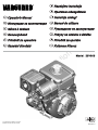 1
1
-
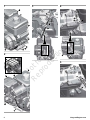 2
2
-
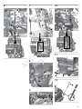 3
3
-
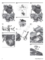 4
4
-
 5
5
-
 6
6
-
 7
7
-
 8
8
-
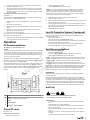 9
9
-
 10
10
-
 11
11
-
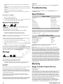 12
12
-
 13
13
-
 14
14
-
 15
15
-
 16
16
-
 17
17
-
 18
18
-
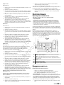 19
19
-
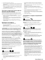 20
20
-
 21
21
-
 22
22
-
 23
23
-
 24
24
-
 25
25
-
 26
26
-
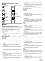 27
27
-
 28
28
-
 29
29
-
 30
30
-
 31
31
-
 32
32
-
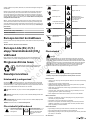 33
33
-
 34
34
-
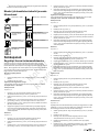 35
35
-
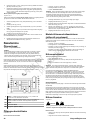 36
36
-
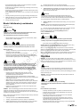 37
37
-
 38
38
-
 39
39
-
 40
40
-
 41
41
-
 42
42
-
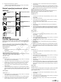 43
43
-
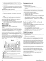 44
44
-
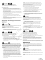 45
45
-
 46
46
-
 47
47
-
 48
48
-
 49
49
-
 50
50
-
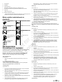 51
51
-
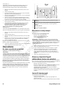 52
52
-
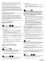 53
53
-
 54
54
-
 55
55
-
 56
56
-
 57
57
-
 58
58
-
 59
59
-
 60
60
-
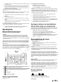 61
61
-
 62
62
-
 63
63
-
 64
64
-
 65
65
-
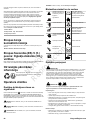 66
66
-
 67
67
-
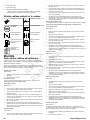 68
68
-
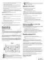 69
69
-
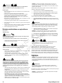 70
70
-
 71
71
-
 72
72
-
 73
73
-
 74
74
-
 75
75
-
 76
76
-
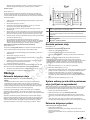 77
77
-
 78
78
-
 79
79
-
 80
80
-
 81
81
-
 82
82
-
 83
83
-
 84
84
-
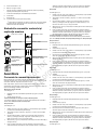 85
85
-
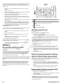 86
86
-
 87
87
-
 88
88
-
 89
89
-
 90
90
-
 91
91
-
 92
92
-
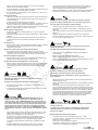 93
93
-
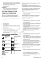 94
94
-
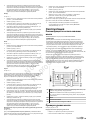 95
95
-
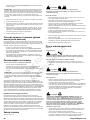 96
96
-
 97
97
-
 98
98
-
 99
99
-
 100
100
-
 101
101
-
 102
102
-
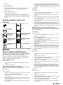 103
103
-
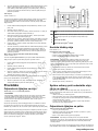 104
104
-
 105
105
-
 106
106
-
 107
107
-
 108
108
-
 109
109
-
 110
110
-
 111
111
-
 112
112
-
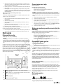 113
113
-
 114
114
-
 115
115
-
 116
116
-
 117
117
-
 118
118
-
 119
119
-
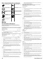 120
120
-
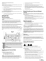 121
121
-
 122
122
-
 123
123
-
 124
124
-
 125
125
-
 126
126
-
 127
127
-
 128
128


Simplicity 10V332-S016-97 Kullanım kılavuzu
- Kategori
- Motorlu taşıt aksesuarları
- Tip
- Kullanım kılavuzu
- Bu kılavuz için de uygundur
Diğer dillerde
İlgili Makaleler
-
Simplicity 25V337-0012-F1 Kullanım kılavuzu
-
Simplicity 10V362-0030-F1 Kullanım kılavuzu
-
Simplicity 12V332-0026-F1 Kullanım kılavuzu
-
Simplicity 13H332-0146-B8 Kullanım kılavuzu
-
Simplicity 19L237-0056-F1 Kullanım kılavuzu
-
-
-
Simplicity 613477-3035-J1 Kullanım kılavuzu
-
Simplicity 613477-4214-J1 Kullanım kılavuzu
-
Simplicity 297440-0008-G1 Kullanım kılavuzu