

2

3
Contents
Playing Arpeggiated Chords...........................................35
Arpeggio MIDI Output....................................................37
Using The Step Sequencer
..........................................37
Step Sequencer On/Off .................................................38
Step Sequencer Hold Modes...........................................38
Voice Pattern And User Pattern Banks...............................39
Playing Step Sequencer Patterns......................................40
Step Sequencer Edit.......................................................44
Step Sequencer MIDI Output...........................................46
Using The Free EG
......................................................47
Free EG Parameters .......................................................47
Using The Control Features
.........................................49
Real-time Control............................................................49
Utility Control Assign Function.........................................50
Control Matrix...............................................................51
FEATURE REFERENCE
Voice Select
.................................................................52
Knob Edit
....................................................................53
Knob Parameters
.......................................................54
PEG/LFO......................................................................54
SYNC/FM ....................................................................58
VCO1 ..........................................................................61
VCO2 ..........................................................................63
VCF..............................................................................64
MIX/VCF ......................................................................66
VCA.............................................................................68
ASSIGN .......................................................................70
Panel Parameter Edit
..................................................71
Edit Procedure...............................................................71
Edit Parameters
..........................................................72
VOICE SCENE SETUP ....................................................72
VOICE COMMON ........................................................77
VOICE FREE EG ............................................................81
VOICE ARPEGGIO/SEQ ................................................85
SEQ EDIT/SETUP...........................................................89
UTILITY SETUP................................................................92
Voice Recall
................................................................96
Voice Initialize
............................................................97
Store
...........................................................................98
Voice Store....................................................................98
Scene Store...................................................................99
Factory Settings
........................................................100
APPENDIX
Voice Creation Examples
..........................................101
About MIDI
...............................................................109
Error Messages
.........................................................112
Troubleshooting
........................................................113
Blank Chart
..............................................................114
Specifications
............................................................116
Index
........................................................................117
PRECAUTIONS ............................................................
4
INTRODUCTION
How To Use This Manual
..............................................5
Main Features
...............................................................5
The AN1x At A Glance
.................................................6
The Making Of A Modern Classic
.................................8
What Is A Voice?
..........................................................9
AN1x Memory Structure
..............................................9
ANALOG PHYSICAL
MODELING SYNTHESIS
AN1x Tone Generator
................................................10
GETTING STARTED
System Examples
.......................................................12
Switching On The Power ................................................13
Playing The Demo Songs
............................................13
Basic Operation
..........................................................14
AN1x Operating Modes.................................................14
Selecting Voices.............................................................14
Using The Controllers .....................................................15
CONTROL Knobs And Parameter Groups.........................16
AN1x Quick Tour
........................................................17
Exploring The Factory-set Voices......................................17
Selecting Scenes And Scene Morphing
.......................19
Scene Memories............................................................19
Scene Control................................................................20
Scene Store Function......................................................21
Scene Load Function ......................................................22
Scene Swap Function .....................................................22
Selecting Layer Modes
................................................22
Layer Modes .................................................................22
Portamento Play
.........................................................24
Turning PORTAMENTO On And Off.................................24
Setting Portamento Time..................................................25
Selecting Portamento Modes ...........................................25
Selecting Parameter Groups
.......................................25
Using The CONTROL Knobs
........................................26
Assigning Parameters To Knobs.......................................27
Using The Panel Edit Matrix
.......................................28
Editing Voices
.............................................................29
Voice Edit Procedure ......................................................29
Creating Original Voices ................................................30
Store Operations
........................................................33
Turning ARPEGGIO/SEQ On And off
..........................33
Using The Arpeggiator
...............................................33
Arpeggiator On/Off ......................................................33
Arpeggio Hold Function..................................................34
Arpeggio Pattern Types...................................................34
Arpeggio Subdivide.......................................................34

4
PRECAUTIONS
PLEASE READ CAREFULLY BEFORE PROCEEDING
* Please keep these precautions in a safe place for future reference.
WARNING
Always follow the basic precautions listed below to avoid the possibility of serious injury or even death from electrical
shock, short-circuiting, damages, fire or other hazards. These precautions include, but are not limited to, the following:
• Do not open the instrument or attempt to disassemble the internal parts
or modify them in any way. The instrument contains no user-
serviceable parts. If it should appear to be malfunctioning, discontinue
use immediately and have it inspected by qualified Yamaha service
personnel.
• Do not expose the instrument to rain, use it near water or in damp or
wet conditions, or place containers on it containing liquids which
might spill into any openings.
• If the AC adaptor cord or plug becomes frayed or damaged, or if there
is a sudden loss of sound during use of the instrument, or if any
unusual smells or smoke should appear to be caused by it,
immediately turn off the power switch, disconnect the adaptor plug
from the outlet, and have the instrument inspected by qualified Yamaha
service personnel.
• Use the specified adaptor (PA-3B or equivalent, recommended by
Yamaha) only. Using the wrong adaptor can result in damage to the
instrument or overheating.
• Before cleaning the instrument, always remove the electric plug from
the outlet. Never insert or remove an electric plug with wet hands.
• Check the electric plug periodically and remove any dirt or dust which
may have accumulated on it.
CAUTION
Always follow the basic precautions listed below to avoid the possibility of physical injury to you or others, or damage
to the instrument or other property. These precautions include, but are not limited to, the following:
• Do not place the AC adaptor cord near heat sources such as heaters or
radiators, and do not excessively bend or otherwise damage the cord,
place heavy objects on it, or place it in a position where anyone could
walk on, trip over, or roll anything over it.
• When removing the electric plug from an outlet, always hold the plug
itself and not the cord.
• Do not connect the instrument to an electrical outlet using a multiple-
connector. Doing so can result in lower sound quality, or possibly
cause overheating in the outlet.
• Remove the adaptor plug from the outlet when the instrument is not to
be used for extended periods of time, or during electrical storms.
• Before connecting the instrument to other electronic components, turn
off the power for all components. Before turning the power on or off for
all components, set all volume levels to minimum.
• Do not expose the instrument to excessive dust or vibrations, or
extreme cold or heat (such as in direct sunlight, near a heater, or in a
car during the day) to prevent the possibility of panel disfiguration or
damage to the internal components.
• Do not use the instrument near other electrical products such as
televisions, radios, or speakers, since this might cause interference
which can affect proper operation of the other products.
• Do not place the instrument in an unstable position where it might
accidentally fall over.
• Before moving the instrument, remove all connected adaptor and other
cables.
• When cleaning the instrument, use a soft, dry cloth. Do not use paint
thinners, solvents, cleaning fluids, or chemical-impregnated wiping
cloths. Also, do not place vinyl or plastic objects on the instrument,
since this might discolor the panel or keyboard.
• Do not rest your weight on, or place heavy objects on the instrument,
and do not use excessive force on the buttons, switches or connectors.
• Do not operate the instrument for a long period of time at a high or
uncomfortable volume level, since this can cause permanent hearing
loss. If you experience any hearing loss or ringing in the ears, consult
a physician.
■ REPLACING THE BACKUP BATTERY
• This instrument contains a non rechargeable internal backup battery
which permits internal data to remain stored even when the power is
off. When the backup battery needs replacing, the message "Battery
Low" will display in the LCD. When this happens, immediately back up
your data (using an external device such as the floppy disk-based
Yamaha MIDI Data Filer MDF2), then have qualified Yamaha service
personnel replace the backup battery.
• Do not attempt to replace the backup battery yourself, in order to
prevent the possible serious hazards. Always have qualified Yamaha
service personnel replace the backup battery.
• Never place the backup battery in a location that a child can reach,
since a child might accidentally swallow the battery. If this should
happen, consult a physician immediately.
■ SAVING USER DATA
• Save all data to an external device such as the Yamaha MIDI Data Filer
MDF2, in order to help prevent the loss of important data due to a
malfunction or user operating error.
Yamaha cannot be held responsible for damage caused by improper use or
modifications to the instrument, or data that is lost or destroyed.
Always turn the power off when the instrument is not in use.
The LCD screens and diagrams in this owner's manual are for
instructional purposes only, and may be different from the ones on your
instrument.

5
How To Use This Manual
This owner’s manual provides your basic keys to unlocking the power of
the AN1x Control Synthesizer. It is divided into the following sections:
INTRODUCTION Provides a brief rundown of the AN1x’s main
features and description of all front and rear panel controls along
with information about the AN1x’s memory
structure
. We
recommend you take a few minutes and read the
INTRODUCTION section carefully before you get started in order
to familiarize yourself with the basic features and capabilities of
the AN1x.
ANALOG PHYSICAL MODELING SYNTHESIS Provides an
overview of the basic concept of the tone generation technology,
plus descriptions of basic terminology and a signal flow block
diagram,
in order to give you an understanding of what’s going on
inside the instrument as you twiddle the knobs and set parameters.
Congratulations! And thank you for choosing Yamaha. You are now the proud owner of the AN1x Control Synthesizer, a
fully-professional digital keyboard with powerful sound and versatile real-time control features. The AN1x is a modern
music dynamo capable of faithfully delivering the warm, fat, punchy sounds of the legendary analog synths—with the
same familiar oscillator, filter and other sound creation elements and intuitive, "hands on" style of operation—plus all the
sophisticated flexibility you'd expect from a professional digital synthesizer.
GETTING STARTED Provides a basic overview of how to set up
your AN1x and quickly familiarize yourself with all its key features
and operations. We recommend you actually be sitting in front of
your AN1x as you read through the GETTING STARTED section,
so you can try out each feature along the way to get a thorough
understanding of how the AN1x works.
FEATURE REFERENCE Provides a comprehensive explanation of
all AN1x features. This is in essence a dictionary which you can
refer to any time you need to know the details about any given
feature.
APPENDIX Provides information related to MIDI, troubleshooting,
and more.
A separate Data List book provides voice, Arpeggiator Type, Effect
Type and other lists and information.
Main Features
The AN1x Control Synthesizer is a truly innovative professional keyboard with enormously flexible
sound and performance capabilities. Following is a brief rundown of the main features:
Analog Physical Modeling synthesis
The AN1x generates amazingly high quality synth sounds in much the same way as traditional
legendary analog synthesizers—using voltage controlled oscillators and filters, low frequency
oscillators, ring modulator and voltage controlled amplifiers—but with the additional benefits
of digital multi-effects, MIDI control and much more.
128 voices and maximum 10 notes polyphony
The AN1x comes with an impressive array of 128 voices preprogrammed and ready to play, each of which
can be edited and overwritten to store your own. Ten notes of polyphony provide for versatile SINGLE,
DUAL and SPLIT play options.
Intuitive interface with "hands on" voice editing and multiple assignable
real-time controllers
The AN1x's eight CONTROL knobs and panel Edit matrix give you direct and instant access to
many parameters as you play. All controllers are assignable, including [PITCH] and
[MODULATION] wheels and various foot pedals, plus the [RIBBON] controller with horizontal slide
(X) and pressure (Z) control of filter, LFO, delay and more. The Control Matrix function permits
easy assignment of up to 16 sets of "source" controllers (MW, FC, Key Touch, etc.) to destination
parameters (VCA, Filter, LFO, etc.) for each Scene, all of which can be stored as voice data for
each voice.
2 Scene memories for each voice, with real-time morphing between Scenes
Each voice has two Scenes, each of which can be selected by pressing a [SCENE] switch. This
provides two distinct sounds within each voice available for instant recall as you play. You can
press both [SCENE] switches to activate the "Scene Control" function, and roll the
[MODULATION] wheel (or press a foot pedal or use any other continuous controller) to morph,
or cross-fade between the sounds of Scene 1 and Scene 2 as you play.
Six types of Layers to choose from for each voice
SINGLE, UNISON, DUAL, DUAL UNISON, SPLIT, and SPLIT UNISON Layer modes give you a
wide choice for control over how the two Scenes are configured to play in relation to each
other for each voice.
Arpeggiator with 30 patterns and various play options, plus MIDI data
output
The Arpeggiator lets you play perfect arpeggiated chords at the simple press of a key. You can
have the Arpeggiator play only one or both Scenes, or play one Scene to the left of the Split
Point while you play the other Scene normally to the right. You can choose from various types
of arpeggio patterns, including Up, Down, and Up&Down across one or more octaves, plus
various special patterns including Techno, House, Random, and more. The arpeggio pattern
data can be output via MIDI on its own MIDI channel.
Easy-play/edit “Step Sequencer” with 128 Voice Patterns and 128 User
Patterns
The Step Sequencer permits quick, easy creation of highly sophisticated looped patterns which
can be triggered from the keyboard in a variety of ways. Each individual step event (Note,
Velocity, Gate Time, and Control Change) can be accessed and edited by a specific CONTROL
knob, over a maximum of 16 steps. There are a variety of handy Step Sequencer edit and
play options, including “Play Effects” which give you detailed control over the “feel” of your
sequence. Pattern event data can be output via MIDI on its own MIDI channel.
4-track “Free EG” records and plays real-time changes of knob positions
for up to four different parameters
The 4-track Free EG lets you record real-time CONTROL knob movements, in order to “hand
draw” filter, resonance, LFO and many other available parameters over time—and have them
play back automatically by simply playing a voice. You can control up to four different
parameters independently, each recorded into its own Free EG track. Ideal for those times
when you wish you had an extra couple of pairs of hands, the Free EG lets you build up an
incredibly complex, completely unique voice.
Programmable multi-effects and 3-band EQ for each voice
The AN1x has three types of programmable multi-effects plus EQ built into the voice
architecture, which lets you customize the effects configuration for each voice. There are 8
Reverb effects, 5 Delay effects, 14 Variation effects (which includes Chorus, Auto Pan, Pitch
Change, Compressor, Distortion effects and more), and a stereo 3-band Equalizer. An Effect
Bypass function lets you bypass all effects or specific ones at the press of a switch.

PITCH
MODULATION
VOLUME
CTRL
SCENE
Algorithm
Wave
Attack
Attack
ASSIGN 1 ASSIGN 2
ASSIGN 3
ASSIGN 4
PEG Decay
Wave
VCO1
Fine
Fine
PEG Sw
FM Src2
LFO2 Spd
PmodDepth PmodDepth
Level
LFO1 Wave LFO1 Spd
LFO1 Dly
PW
ASSIGN 5
ASSIGN 6 ASSIGN 7 ASSIGN 8
VCF
Cutoff
Sync
Pmod Sw
Sync Pitch
Pitch Pitch
PEG Depth
Decay
Decay
VCO2
Level
FM Depth
FM Src1
PHONES
L / MONO
OUTPUT
R
DC IN POWER
FOOT
VOLUME
FOOT
CONTROLLER
FOOT
SWITCH
Sync Pitch
Depth
Sustain
Ring
Mod
Sustain
Sync Pitch
Src
Edge
Port Time
Edge
Release
Release
Noise
Level
PW
HPF
Feedback
VCF
PWM Depth
PWM Src PWM Src
PWM Depth
Type
Reso
nance
Volume
FEG
Depth
Fmod
Depth
Amod Depth
Vel
Sens
Key
Track
Vel Sens
IN
OUT
MIDI
THRU
PROGRAM CHANGE
VWX
MNO
7
YZ
8
PQR
5
GHI
2
–
4
DEF
1
ABC
0
OTHERS
STU
9
6
JKL
3
YES/ ENTERNO
DEMO
PORTAMENTO
STORE
ARPEGGIO/SEQ
LAYER
Mode
Poly
Temp
Track
Trigge
Comm
Arp /S
Knob
Event
Syste
Mstr Tu
KNOB PARAMETER GROUP
PEG/ LFOSYNC/FM
VCO1
VCO2
MIX/VCF
VCF
VCA
ASSIGN
[VOLUME] knob
This knob controls the AN1x’s overall
volume level output from the PHONES
and OUTPUT jacks. Turn the [VOLUME]
between left-most (minimum) and right-
most (maximum) positions to set the
proper listening level whether using
headphones or amplified speakers.
[SCENE] switches
Each of the AN1x's 128 voices has two Scene
memories, each of which are instantly accessible
by pressing the [SCENE 1] or [SCENE 2] switch.
Each Scene can have its own distinct sound.
Pressing both [SCENE] switches simultaneously
activates the Scene Control function, which lets you
"morph", or cross-fade between Scenes in real-
time using the assignable [MODULATION] wheel,
an assignable Foot Controller, or any other
continuous controller.
[RIBBON] controller
The assignable [RIBBON] controller gives you
horizontal slide (X) and pressure (Z) control of
designated controllable parameters as you play,
including filter cutoff, resonance, LFO, panpot,
reverb, and more.
[PITCH] wheel
The [PITCH] wheel lets you bend the pitch up or
down as you play. It is spring-loaded to
automatically return to center position when you let
go of it. You can use the Control Matrix to designate
specific Pitch Bend parameters for the upper and
lower bend ranges for each Scene.
[MODULATION] wheel
The assignable [MODULATION] wheel lets you
apply modulation or another designated
controllable parameter as you play, or morph
between Scenes when the Scene Control function is
active (and the [MODULATION] wheel is
designated as the source controller).
CONTROL knobs with push-switch (knob parameters)
The eight assignable CONTROL knobs are used for real-time control and edit of the various tone
generator parameters, depending on which KNOB PARAMETER GROUP select switch is currently
selected, plus instant access to each step event when the [EDIT ROTARY] switch is set to the SEQ
EDIT/SETUP menu. Press a CONTROL knob (push-switch) to confirm the current parameter in the LCD.
Turn a CONTROL knob left to decrease values or right to increase them. Make fine edit adjustments by
turning a knob while pressing it. Since all CONTROL knobs are assignable, you can have each one
access one of many different available parameters to give you maximum real-time control over specific
aspects of your sound, including versatile control of external instruments via MIDI output.
PROGRAM
The PROGRAM
used for selectin
currently selecte
Other functions
naming a User v
canceling ([NO]
operations.
LCD
The back-lit LCD
Display) provide
of information w
indicates the cu
status of the AN
voices, turn kno
switches.
KNOB PARAMETER GROUP switches
These switches determine which set of parameters are
controlled by the CONTROL knobs. The switches are
color coded in cross-reference to the parameter names
as printed in the same color on the panel beside each
knob. Whenever you select a voice, the [ASSIGN]
switch is automatically selected, to give you instant
access to your assigned CONTROL knob parameters.
The AN1x At A
Front Panel
Rear Panel
1 MIDI terminals
MIDI [IN], [OUT] and [THRU] terminals let you connect external MIDI
devices such as a MIDI keyboard, tone generator, sequencer or
computer or others, using a MIDI cable. [IN] is for input of MIDI data,
including data dumps from another AN1x or MIDI data storage
device. [OUT] is for output of MIDI data, including data dumps to
another AN1x or MIDI data storage device. [THRU] is for “daisy-
chain” connection of additional MIDI instruments, as the MIDI data
received at the AN1x’s [IN] terminal is passed along unchanged to
the [THRU] terminal.
2 [FOOTSWITCH
An optional Yamaha
used to control hold
3 [FOOT CONTRO
An optional Yamaha
used for control of va
assignment.
4 [FOOT VOLUM
An optional Yamaha
to regulate overall vo
5 [POWER] switc
Press the [POWER] s
FOOT
VOLUME
FOOT
CONTROLLER
FOOT
SWITCH
ON OFF
DC IN R L/MONO
OUTPUT PHONES
POWER
ASSIGNABLE
MIDI
OUTTHRU IN
6

T
DI
THRU
PROGRAM CHANGE
VWX
MNO
7
YZ
8
PQR
5
GHI
2
–
4
DEF
1
ABC
0
OTHERS
STU
9
6
JKL
3
YES/ ENTERNO
DEMO
PORTAMENTO
STORE
ARPEGGIO/SEQ
LAYER
CONTROL SYNTHESIZER
ANALOG PHYSICAL MODELING
CTRL
PEG
LFO2 LFO1
VCO
VCO1
SYNC
MASTER
SLAVE
FM
VCO2
MIX/VCF
MOD
RING
NOISE
VCA
VOLUME
AEG
FEEDBACK
VARI
EQ
DLY REV
EFFECT
Mode
Poly
Por t
Tempo Split Pnt
Track Common
Trigger
LoopType
Common
Arp /SEQ
Type/No
Knob
Event
1-8/9-16
System
Mstr Tune
Kbd Trans
VOICE
SCENE SETUP
VOICE
COMMON
VOICE
FREE EG
VOICE
ARPEGGIO/SEQ
SEQ
EDIT /SETUP
UTILITY
SETUP
LFO Rst
Ctrl Matrix
Set No
Vari EF/EQ
Param Data
Length
Key Track
KbdMode Hold
Step Hold
Pattern
Bank
Kbd Vel
MIDI
Tx Ch
Param Source
Dly/ Rev EF
Param
Param
Track
Track No
SceneSw
MIDI
Ptn Tx Ch
No
Base Unit
DeviceNo Local
BulkDump
Length LoopType
Arpeggio
Subdivide
Play EF
Swing
Scene Sw
Track Job
Rec
Data
Depth
EF
Bypass
Layer
Pan
Separate
Unison
Detune
Name
Cursor Char
Copy Undo
Velocity
GateTime
Ctrl No
SEQ
Store
Ctrl
Device
Ctrl No
.
y
c
PROGRAM CHANGE keypad
The PROGRAM CHANGE keypad is primarily
used for selecting a voice or confirming the
currently selected voice name and number.
Other functions include selecting letters when
naming a User voice, and confirming ([YES]) or
canceling ([NO]) specific store and other
operations.
[PORTAMENTO] switch
For turning the portamento function on and off.
[LAYER] switch
For selecting one of the six Layer modes.
[STORE] switch
For initiating Store operations.
[ARPEGGIO/SEQ] switch
For turning the Arpeggiator or Step Sequencer
on and off.
DEMO
Pressing [PORTAMENTO] and [LAYER]
simultaneously lets you access the
Demonstration songs.
[EDIT ROTARY]
switch
The 6-position [EDIT
ROTARY] switch lets you
designate one of the six
Edit menus, as printed on
the panel to the right of
each menu.
LCD
The back-lit LCD (Liquid Crystal
Display) provides various types
of information which clearly
indicates the current operating
status of the AN1x as you select
voices, turn knobs and press
switches.
es
s
At A Glance
Synthesis Block Diagram
The Analog Physical Modeling synthesis
block diagram provides a handy visual
reference or reminder of how the signal
flows through the key blocks, or
components of the AN1x's tone
generation architecture, which is helpful
when manipulating the various
parameters during voice editing or real-
time sound control.
Parameter value [UP/DOWN] switches
These ten switches are used to access and edit specific parameters (as printed on the
panel), depending on which Edit menu is currently selected with the [EDIT ROTARY]
switch. Pressing the upper area of a parameter value [UP/DOWN] switch
increments the parameter value or setting, and pressing the lower area decrements
it. Simply pressing a switch once will display the parameter name and current value
or setting in the LCD. Thereafter, pressing or holding the upper or lower area of the
switch will change the value or setting accordingly.
Keyboard
The 61-key touch-sensitive
keyboard features Initial
(velocity) and After Touch
(pressure) control.
al MIDI
or
DI data,
ge
s to
sy-
data
ed to
2 [FOOTSWITCH] jack
An optional Yamaha FC4 or FC5 Footswitch connected to the [FOOTSWITCH] jack can be
used to control hold on/off, Portamento on/off and other discrete controllers.
3 [FOOT CONTROLLER] jack
An optional Yamaha FC7 foot controller connected to the [FOOT CONTROLLER] jack can be
used for control of various continuous or discrete controllers, depending on controller
assignment.
4 [FOOT VOLUME] jack
An optional Yamaha FC7 foot controller connected to the [FOOT VOLUME] jack can be used
to regulate overall volume (or any other assigned continuous controller function.).
5 [POWER] switch
Press the [POWER] switch to turn the AN1x on and off.
6 [DC IN] terminal
Connect the supplied Yamaha PA-3B Power Adaptor to the [DC IN] terminal.
(CAUTION: Do not attempt to use an AC adaptor other than the Yamaha PA-3B or
equivalent, since the use of an incompatible adaptor may cause irreparable damage to
the AN1x, and may even pose a serious shock hazard.)
7 OUTPUT jacks
The stereo OUTPUT jacks let you connect the AN1x to an external stereo
amplifier/speaker system. When using a mono system, connect it to the [L/MONO]
jack.
8 [PHONES] jack
The [PHONES] jack lets you connect a set of stereo headphones to the AN1x for private
listening.
7

8
The History…
Why is the “analog sound” so popular in a digital
age? What long and winding road had to be
traveled—just to end up right back where we started
from? Let’s take a quick look at how we got from there
to here, and where here really is, anyway.
Electronic music synthesis has been around in one form
or another since the beginning of the 20th Century. But
it wasn’t until the early 1970s that developments in
voltage controlled synthesis technology made the
concept practical—and affordable.
As such, the voltage controlled synthesizer became less
and less an experimental curiosity in the world’s great
universities and sound labs and more and more a
valid—and revolutionary—musical instrument in its own
right. It quickly became a staple in professional
recording studios, and its myriad sounds started
gracing the ears of millions through popular recordings
in literally all genres of music.
Then came the 1980s, and the introduction of wildly
popular, affordable-for-the-masses, great-sounding and
easy-to-use digital synths like the famous Yamaha DX7.
What followed was the MIDI revolution, which drove
the rapid development of ever-more-sophisticated multi-
timbral digital synthesizers and tone generators, along
with the overwhelming acceptance of digital sampling
which has literally changed the way we create and
listen to music. And all of which have gone hand-in-
hand with the desktop music revolution.
Most recently there has been the introduction of
breakthrough physical modeling synthesis technology,
which has been successfully applied to the accurate
reproduction of acoustic instrument sounds through
purely electronic means, as well as the creation of new
“hybrid-type” acoustic-oriented sounds.
The Making Of A Modern Classic
The classic analog synth sound is back with a vengeance and more popular than ever. Vintage analog synthesizers are hot
items, recirculating and finding their way into the arsenals of the world’s most innovative music makers, many of whom
weren’t even born when the voltage controlled synthesizer was coming of age more than a quarter of a century ago.
Enter the Yamaha AN1x Control Synthesizer—a modern classic in its own right—complete with the VCO, VCF, and VCA
blocks, or "modules" that give retro synths that famously fat, rich, warm sound, plus multiple knobs for controlling every nuance
of the sound, and even an on-board Arpeggiator and Step Sequencer for generating pattern loops at the press of a key.
What’s much more, however, is that the AN1x incorporates features that vintage synths could only dream about—like three on-
board programmable digital multi-effects units and a 3-band stereo EQ, a multiple controller-to-parameter assignment architecture,
a 4-track Free EG for “hand drawing” real-time knob position movements of up to four different tone generator parameters, plus
real-time morphing between two different sounds, and more—all of which can be customized for each of the 128 voices and
stored as individual voice data.
Enter Analog Physical
Modeling…
The classic analog synth never fell out of favor with the
world's most innovative musicians. That's because it
has a special punch, power, plus important elements of
interactivity that digital synths and samplers have
tended to lack by comparison.
And now, with the demand for that "classic analog
sound" due to the global popularity of techno, trance,
and other modern forms of dance music, it's hardly
surprising that Yamaha—a company consistently at the
very pinnacle of electronic musical instrument
technology—would react to that demand and create a
completely new performance-oriented "control
synthesizer" that takes the company's original
breakthroughs in physical modeling synthesis and uses
it to digitally "model" the analog sound-generating
components which gives voltage controlled synthesis its
unique character and virtually unlimited range of
sound.
And package it with a host of digital extras to bring
the technology full circle with a completeness and utility
never before possible.
In short, the AN1x is a logical—and timely—
development in the evolution of electronic musical
instrument history, based on the modern needs and
demands of the world’s cutting-edge musicians. And
once again, as is often the case with creations from
Yamaha, music history will never be the same.
All the tools are in the box. The rest is up to you….

9
What Is A Voice?
Over the years, the meaning of the term “voice”, when
applied to synthesizers, has varied depending on
manufacturers and models. In general, it means a sound,
which in some synths is called a “patch”, and in others a
“program”.
With the AN1x, a voice is a configuration of all tone
generator and other parameter settings, including effects
setups and data for a single Voice Pattern, but excluding
system settings or the bank of Step Sequencer User
Patterns. Therefore, each of the 128 voices in memory
can have its own unique configuration of all main
parameters.
AN1x Memory Structure
The AN1x has a simple and straightforward memory structure. There
are only two main types of data: voice data and system data. There
is also a separate memory for the Step Sequencer User Pattern bank.
Voice Data
Voice data is comprised of the various parameter
settings which make up each of the 128 User voices,
as follows:
● Tone generator settings based on CONTROL knob
positions for each KNOB PARAMETER GROUP
parameter, PORTAMENTO switch status, Scene
status and Scene-related parameters, including
Control Matrix assignments, Mode settings and
Variation Effect Dry:Wet setting.
● LAYER mode setting and Layer parameters including
Pan, Separation and Detune settings.
● VOICE COMMON (i.e., parameters which affect
both Scenes) settings including Tempo, Split Point,
Effect configurations and voice Name.
● Free EG parameter settings and track data and
other settings.
● ARPEGGIO/SEQ switch status and the various
Arpeggiator and Step Sequencer parameter
settings, including Play Effect settings, plus Step
Sequencer Voice Pattern data.
System Data
System data is made up of the various “global”
parameter settings which remain in effect regardless of
which voice is selected, as follows:
● UTILITY SETUP parameters, including the settings for
System tuning and keyboard transposition and
velocity, MIDI-related parameters, and Control
device and number assignments.
User Pattern Data
User Pattern data is made up of the Step Sequencer
User Pattern bank which holds 128 User Patterns.
Voice Data 128 User Voices
SCENE 1
Utility Setup Parameters
SYSTEM: MASTER TUNE, VELOCITY,
KEYBOARD TRANSPOSE
MIDI: TRANSMIT CHANNEL,
RECEIVE CHANNEL (each Scene),
PATTERN TRANSMIT CHANNEL,
DEVICE NUMBER, LOCAL,
BULK DUMP, EFFECT BYPASS
CONTROL: ASSIGNABLE KNOB CONTROL
CHANGE NUMBERS, CONTROLLER
CONTROL CHANGE NUMBERS
Layer Parameters
PAN, SEPARATE, DETUNE
Voice Common Parameters
TEMPO, SPLIT POINT, EFFECT, NAME
Pattern Parameters
ARPEGGIATOR or SEQUENCER,
ARPEGGIATOR PATTERN NUMBER,
VOICE PATTERN, KEYBOARD MODE, HOLD,
SCENE SWITCH, SUBDIVIDE (Arpeggiator only),
PLAY EFFECT (Arpeggiator = Velocity only)
Free EG Parameters
TRIGGER MODE, LOOP TYPE, LENGTH, KEY TRACK
SCENE 2
LAYER
(SINGLE/UNISON/
DUAL/DUAL UNISON/
SPLIT/SPLIT UNISON)
PORTAMENTO
(On/Off)
ARPEGGIO/SEQ
(On/Off)
Tone Generator Knob Parameters
PEG, LFO1, LFO2, VCO1, VCO2, SYNC, FM, MIXER
(NOISE, RING MODULATOR), VCF (FEG), VCA (AEG)
Scene Setup Parameters
POLY/MONO/LEGATO, PORTAMENTO MODE,
LFO RESET, CONTROL MATRIX (Assignments),
VARIATION EFFECT DRY:WET
System Data
Step Sequencer
(User Pattern Bank)
No (1 ~ 128)

10
AN1x Tone Generator
As the AN1x Tone Generator Block Diagram
illustrates, the VCO module generates the basic
signal, then passes it along the signal path to
the MIX/VCF module, which processes the signal
in a variety of ways before passing it on to the
VCA module, which amplifies the signal before
passing it along the signal path to the EFFECT
module comprised of three multi-effects units
and a stereo equalizer, after which the signal is
output from the AN1x's stereo outputs. Along
the way, various real-time and other controllers
can be applied to each module in a variety of
ways.
Oscillators, Filters And Amplifiers
What does it take to make a sound? And how does the
AN1x generate sounds?
In the simplest of terms, there are three basic elements which
make up a sound: pitch, or how low or high it is; tone, or
what its overall quality, or timbre is like; and amplitude, or
how loud the volume level is.
Synthesizers rely on three key electronic components to generate
sounds and electronically imitate the soundwaves of familiar musical
instruments, as well as create entirely unique sounds. In traditional
analog synthesis, the source sound pitch is generated by an
oscillator; its tone is created by a filter; and its volume is determined
by an amplifier. With the AN1x, these three elements are termed
the VCO (voltage controlled oscillator), the VCF (voltage controlled
filter), and the VCA (voltage controlled amplifier).
The “signal path” starts at the VCO, flows to the VCF, then
flows to the VCA. The signal is “processed” at each block, or
“module” along the way to the final output.
VCO VCF VCA OUT
The amplifier determines
the volume
The oscillator creates the source pitch
The filter determines the timbre
1 VCO
The VCO module is where the original sound waveform gets
generated. Although a single oscillator is enough to generate
the basic sawtooth, pulse (square) or other waves required
for different types of musical instrument sounds, the AN1x’s
VCO module is much more complex.
First, there’s a VCO1 which includes an additional saw2 and
mix wave, and which can be configured with one of three
“sync algorithms” that syncs “master” and “slave” oscillators
within the VCO1, and can be modulated by FM according to
the algorithm. Thus, when the sync is on, the VCO1 is
actually two oscillators in one, and three additional “inner”
waves are available.
The VCO1 is always fixed as the FM carrier, but the carrier
can either be the master or slave oscillator depending on the
selected algorithm. The FM modulator can be selected from a
second VCO (VCO2), the PEG, FEG, LFO1, LFO2 or others.
The Pitch Envelope Generator (PEG) lets you determine how
the pitch of the VCO changes over time, and the LFO can be
used to modulate the VCO to create vibrato.
For more information, see as follows:
VCO1 — page 61
VCO2 — page 63
SYNC/FM — page 58
PEG/LFO — page 54
2 MIX/VCF
The MIX/VCF module is where the mixing of VCO1,
VCO2, Ring Modulator, Noise and Feedback signals
take place, which can then be filtered by the VCF High
Pass Filter (HPF), Low Pass Filter (LPF), Band Pass Filter
(BPF) and Band Eliminate Filter (BEF). You can
determine the cutoff frequency of the VCF, as well as
amount of Resonance, or emphasis around the
frequency cutoff point. The Filter Envelope Generator
(FEG) lets you determine how the timbre of the signal
changes over time, and the LFO1 can be used to
modulate the VCF to create wah.
For more information, see as follows:
MIX/VCF — page 66
VCF — page 64
HPF — page 67

11
LPF, HPF, BPF, BEF — page 67
FEG — page 31
PEG/LFO — page 54
RING MODULATOR — page 66
NOISE — page 66
3 VCA
The VCA module is where the overall output level of
the signal gets determined, as well as the Feedback
level which gets “fed back” to the mixer in the
MIX/VCF module. The Amplitude Envelope Generator
(AEG) lets you determine how the volume of the signal
changes over time, and the LFO1 can be used to
modulate the VCA to create tremolo.
For more information, see as follows:
VCA — page 68
VOLUME — page 69
FEEDBACK — page 69
AEG — page 32
PEG/LFO — page 54
4 EFFECT
The EFFECT module is where three different types of
programmable effects, as well as programmable 3-band
EQ, can be applied. The 14 Variation Effects include
Chorus, Flanger, Phaser, Auto Pan, Rotary Speaker,
Pitch Change, Aural Exciter, Compressor, Distortion,
Overdrive, Amp Simulator and more. The 5 Delay
effects include Delay LCR, Delay LR, Echo, and Tempo
Delay, which automatically matches the delay time to the
current tempo setting. The 8 Reverb effects include
various Hall, Room and Stage types and more. Delay
and Reverb effects can be configured in a serial or
parallel connection, and specified effects or all effects
(excluding the EQ) can be bypassed at will. Controllers
can be designated to control specific effect parameters.
For more information, see as follows:
Vari EF/EQ — page 77
Dly/Rev EF — page 79
EF Bypass — page 80
5 CONTROL
Specific parameters of the VCO, MIX/VCF, VCF, VCA
and EFFECT modules, as well as the PEG, LFO1 and
LFO2 can be controlled by many different types of real-
time controllers, including [MODULATION] wheel,
[RIBBON] controller X- or Z-axis, the eight assignable
CONTROL knobs, a connected [FOOT CONTROLLER],
keyboard After Touch, and more, including MIDI
Control Change messages received at the MIDI [IN]
terminal.
The AN1x’s Control Matrix and UTILITY SETUP Control
Assign function work together flexibly to give you
complete authority over which on-board or external
controller controls which individual internal or external
parameter.
For more information, see as follows:
Control Features — page 49
Control Matrix — pages 51, 73
Utility Control Assign — pages 50, 95
VCO
VCO1
SYNC
MASTER
SLAVE
FM
VCO2
VCA
VOLUME
AEG
FEEDBACK
VARI
EQ
DLY REV
EFFECT
AN1x Tone Generator Block Diagram
MIX/VCF
MOD
RING
NOISE
FEG
MIX HPF
VCF
CTRL
PEG
LFO2 LFO1

12
To avoid possible damage to the speakers or other connected electronic devices, before switching on the
power of any device, make sure the AN1x’s [VOLUME] level and the volume levels of the connected
equipment are set to minimum positions.
The AN1x In A MIDI System
It’s easy to create a simple but powerful MIDI music
system with only a few basic components. The
illustration below shows how to connect the AN1x to a
Yamaha QY700 Music Sequencer.
You can have the AN1x’s Tempo setting control the
external sequencer’s clock, or the sequencer’s clock
control the speed of the AN1x’s Arpeggiator or Step
Sequencer.
For details about assigning AN1x MIDI transmit and receive channels, see page 93. For
details about assigning MIDI channels and other settings for the external sequencer or other
devices which may be connected, consult the owner’s manual for each. For more
information about MIDI, see the APPENDIX, page 109.
QY700
MIDI OUT
MIDI IN
MIDI IN
AN1x
MIDI OUT
Amp
Mixer
AN1x
Speaker Speaker
Headphones
12345678910111213141516LR
L R INPUT
R OUTPUT
L
R OUTPUTPHONES
L
FC4 FC7
System Examples
There are many ways to incorporate the AN1x into
a simple or expanded music system. Following are
a few of the most common examples.
The AN1x By Itself
At the simplest level, all you need to do is connect
stereo headphones to the [PHONES] jack located on
the rear panel, and you’re ready to go. To use the
AN1x as a stand-alone performance instrument, simply
connect it to amplified speakers and optional FC Foot
Controller and Footswitch pedals as shown in the
diagram at right.
Setting Up Your AN1x
The AN1x Control Synthesizer is an ideal stand-alone performance-
based electronic musical instrument as well as a powerful component
in an expanded MIDI music system. Following are instructions for
proper setup of the AN1x and connection to external devices.
1. After carefully taking your new AN1x out of
the box, place it on a keyboard stand or on
top of a sturdy table or desk.
2. Next, connect the supplied Yamaha PA-3B (or
equivalent) Adaptor to the AN1x’s [DC IN]
connector located on the rear panel. Then
connect the adaptor to the nearest electrical
outlet.
3. Before switching on the power, connect any
peripheral devices such as amplified speakers,
FC Foot Controller or Footswitch pedals, or
external MIDI instruments.
Do not attempt to use an AC adaptor other than the PA-3B (or equivalent). Use of an
incompatible adaptor may result in irreparable damage to the AN1x, and could even pose a
serious shock hazard.
Always be sure to disconnect the power adaptor from the electrical outlet when the AN1x is
not in use.
FOOT
VOLUME
FOOT
CONTROLLER
FOOT
SWITCH
ON OFF
DC IN R L/MONO
OUTPUT PHONES
POWER
ASSIGNABLE
MIDI
OUTTHRU IN
PA-3B Adaptor
DC IN

13
Connecting The AN1x To
A MIDI Data Storage
Device
You can connect the AN1x to a MIDI data storage
device, such as the Yamaha MDF2 MIDI Data Filer, in
order to “bulk dump”, or save AN1x voice, Step
Sequencer and other data to floppy disks. This lets you
build up complete libraries of your favorite sounds,
sequences and settings, which you can easily load
back into the AN1x whenever you wish.
For information about how to perform Bulk Dump operations, see page 94.
Switching On The Power
Once all connections have been properly made, you’re
ready to switch on the power and start making music with
your AN1x.
1. Set the AN1x’s [VOLUME] knob to minimum
position.
2. Press the [POWER] switch, located on the rear
panel.
After a brief greeting message which appears in the LCD,
the AN1x will power up and be ready to go.
3. Gradually turn the [VOLUME] knob to the
right while playing the keyboard until you
achieve a comfortable listening level.
VOLUME
MDR SEO JOB UTIL
MIDI
MIDI DATA FILTER
CURSOR
- FILE DATA +
REC PAUSE START/STOP
TEMPO
MDF2, etc.
AN1x
MIDI IN
MIDI OUT
MIDI IN
MIDI OUT
Playing The Demo
Songs
The AN1x comes preprogrammed with
demonstration songs which provide dynamic
examples of just how powerful the AN1x really
is. To select and play a Demo, perform the
following operation:
1. Press the [PORTAMENTO] and [LAYER]
switches simultaneously. The word “DEMO”
will appear in the LCD.
2. Press a PROGRAM CHANGE switch (0 - 9) to
select one of the 10 Demo songs. After a
brief moment the Demo song will begin, and
continue playing until the end.
3. When the Demo is finished, simply press
[-/NO] to return to normal operating status.
The Demo song will continue playing repeatedly until you stop it. You can stop the
Demo song in the middle of play by pressing [-/NO].
PROGRAM CHANGE
VWX
MNO
7
YZ
8
PQR
5
GHI
2
–
4
DEF
1
ABC
0
OTHERS
STU
9
6
JKL
3
YES/ENTERNO
DEMO
PORTAMENTO LAYER

14
Selecting Voices
The AN1x comes with 128 voices already preprogrammed and
ready to play. Not only are these voices first-rate and highly
useful in their own right, they form a dynamic living example of
the AN1x’s vast sonic range and power, as well as provide an
excellent basis for study of how voices are constructed.
They are also great for use as a starting point for creating your
own voices—by making slight or significant modifications to suit
your needs or taste—which you can then store in the AN1x’s
memory for instant recall at any time.
Of course, if you want to roll up your sleeves and get your
hands on the VCO, VCF and VCA to build up an original
voice from scratch, you can easily initialize a voice (i.e.,
reset each parameter value to its initial setting) and start
from there. The AN1x even provides a few handy
templates which save you time and all the tedious effort by
making all the basic settings for certain types of sounds for
you, so you can pick up from there and concentrate on just
the fun and creative stuff. (See page 30).
Voice Select Operation
Each of the 128 voices has a Program Number
between 001 and 128. You select a voice using the
PROGRAM CHANGE keypad. There are two ways to
do so, as follows:
METHOD 1
Input a number between 1 and 128, then press
[ENTER].
METHOD 2
Press [+] or [–] to increment or decrement through
the voices sequentially.
The voice name, as well as voice Category and
Program Number, appears in the LCD.
PROGRAM CHANGE
VWX
MNO
7
YZ
8
PQR
5
GHI
2
–
4
DEF
1
ABC
0
OTHERS
STU
9
6
JKL
3
YES/ENTERNO
Basic Operation
You'll find the process of getting to know the
AN1x to be fun and inspiring—especially if you
keep a few fundamental things in mind as you
select and play the voices, try out the various
controls and experiment with the panel features
for the first time. Following are some important
aspects about basic operation of the AN1x
which will help you keep things in their proper
context from the very start.
AN1x Operating Modes
For the most part, except when performing a specific Store or
MIDI bulk dump operation, the AN1x is basically always in Voice
Play/Edit mode. This means that during play, as you turn the
various CONTROL knobs, change the parameter values or
settings using the Edit matrix [UP/DOWN] switches, select a
Layer mode, etc., you are actually editing the voice. (The “EDIT”
mark will appear in reverse type in the lower left area of the LCD
the first time any voice data is changed.)
However, these changes only remain in effect as long as the voice
is selected, unless you store the newly edited voice using a Voice
Store operation before selecting another voice. If you don’t store
the changes, they will be lost when you select a different voice.
The AN1x is a very forgiving instrument, however. A Voice
Recall function (see page 96) lets you retrieve the edited data.
Plus, if you turn the power off before storing an edited voice,
when you turn the power back on the edited parameter
settings will still be retained in the voice edit buffer.
There are various other modes, but these are simply sub-modes of
Voice Play/Edit mode (such as Step Sequencer mode for creating
and editing Voice and User Patterns; see page 37), since virtually
all panel settings—including Scene, Layer, Effects, Arpeggiator,
Step Sequencer settings, and more—are stored as voice data for
each voice (excluding system-related settings).

15
Voice Categories
Voices can be organized into Category types and
assigned a two-letter Category code during the voice
Name operation. For a list of the available Category
types, see page 81.
Scenes
Each voice has two “Scenes”, or two distinct sounds
available for instant recall at the press of a [SCENE]
switch. Since the specific Scene on/off status is stored
as voice data, when you select a voice an LED beside
one of the [SCENE] switches will light to indicate which
Scene is active. (If both Scene LEDs light, the Scene
Control on status has been stored as part of the voice,
which means you can morph, or cross-fade between
Scenes using the assignable [MODULATION] wheel or
any other assigned continuous controller as you play.)
For more information about Scenes, see page 19.
Voice Name Display
As you edit a voice by turning the knobs or changing
parameters in the Edit menu, the information in the
screen changes accordingly. To display the voice name
and number in the LCD at any time, press [-] or [+]
once.
Voice Recall
If you’re editing a voice, and inadvertently select
another voice before performing a Voice Store
operation, or simply change your mind, you can recall
the most recently edited voice data using the Voice
Recall function. For more information, see page 96.
–
YES/ENTERNO
or
Press once
Indicates a voice
has been edited
but not stored.
Knob position settings 2
Knob position settings 1
Algorithm
Wave
Attack
Attack
ASSIGN 1 ASSIGN 2
ASSIGN 3
ASSIGN 4
PEG Decay
Wave
VCO1
Fine
Fine
PEG Sw
FM Src2
LFO2 Spd
PmodDepth PmodDepth
Level
LFO1 Wave LFO1 Spd
LFO1 Dly
PW
ASSIGN 5
ASSIGN 6 ASSIGN 7 ASSIGN 8
VCF
Cutoff
Sync
Pmod Sw
Sync Pitch
Pitch Pitch
PEG Depth
Decay
Decay
VCO2
Level
FM Depth
FM Src1
Sync Pitch
Depth
Sustain
Ring
Mod
Sustain
Sync Pitch
Src
Edge
Port Time
Edge
Release
Release
Noise
Level
PW
HPF
Feedback
VCF
PWM Depth
PWM Src PWM Src
PWM Depth
Type
Reso
nance
Volume
FEG
Depth
Fmod
Depth
Amod Depth
Vel
Sens
Key
Track
Vel Sens
CTRL
SCENE
Using The Controllers
The AN1x has various on-board controllers which let you
control specific parameters in real-time as you play.
Besides keyboard Initial and After Touch, these include
[PITCH] wheel, [MODULATION] wheel and [RIBBON]
controller, as well as the eight assignable CONTROL
knobs.
PITCH Wheel
The [PITCH] wheel lets you bend the pitch up or down
by an assignable amount. The pitch bend “depth”
(range) can be different for each Scene, as set in the
Control Matrix.
The pitch bend range can be different for each Scene in each voice. You can also
use the [PITCH] wheel to control other parameters. For information, see page 51.
MODULATION Wheel
The [MODULATION] wheel lets you apply varying
amounts of modulation to the sound as you play,
depending on assignment by the Utility Control Assign
function (see page 50) or in the Control Matrix (see
page 51).
You can also assign volume, pan or one of many other parameters to be
controlled by the [MODULATION] wheel. For information, see page 95. The
[MODULATION] wheel can also be used to “morph” between Scenes when the
Scene Control function is activated. For information, see page 20.
MODULATION
Maximum
Minimum
PITCH
Bends the pitch up
Bends the pitch down

16
RIBBON Controller
The [RIBBON] controller lets you control two different
assignable parameters as you play. You can control
one parameter by sliding your finger along the X-axis,
and another by applying pressure to the Z-axis. You
can assign parameters to the [RIBBON] controller using
the Utility Assign Control function (see page 50) or the
Control Matrix (see page 51).
You can assign different parameters to the [RIBBON] controller for each voice. For
information, see page 75.
To activate the Z-axis you must apply considerable pressure. A light touch will only
apply to the X-axis.
When you release your finger from the [RIBBON] controller, the value may remain
at the same position as at the time of release, or reset to the center position
depending on the Control Matrix setting. (See page 73.)
CONTROL Knobs And
Parameter Groups
Which parameter is edited by each CONTROL knob for
each Scene depends on which KNOB PARAMETER
GROUP switch is currently selected, indicated by a lit LED
to the left of it. Pressing a CONTROL knob (push-switch) or
turning a knob will cause its parameter name and value to
display in the LCD.
When you select a voice the [ASSIGN] switch will
automatically be selected (unless the [EDIT ROTARY] switch
is set to SEQ EDIT/SETUP), which lets you access the eight
parameters assigned to the respective CONTROL knobs.
For more information about the Utility Control Assign function, see pages 50, 95.
KNOB PARAMETER GROUP
PEG/LFOSYNC/FM
VCO1
VCO2
MIX/VCF
VCF
VCA
ASSIGN
ASSIGN 4
Sync Pitch
Src
Edge
Port Time
Edge
Release
Release
Noise
Level
Selected parameter group
Selected CONTROL knob parameter
X-axis
Minimum
Maximum
Z-axis
Apply pressure
When you set the [EDIT ROTARY] switch to the 5th position
(SEQ EDIT/SETUP menu), the CONTROL knobs will be
dedicated to the event parameters of the various steps
(beats) of the Step Sequencer.
In this situation, no LED will be lit in the KNOB
PARAMETER GROUP section, and the name of the current
step event parameters will appear in the LCD when you
turn or press a knob.
Simply pressing a KNOB PARAMETER GROUP switch will
revert the status back to normal tone generator parameter
control, as will selecting a different Edit menu with the
[EDIT ROTARY] switch. As long as the [EDIT ROTARY]
switch is still set to the SEQ EDIT/SETUP menu, however,
you can press the selected KNOB PARAMETER GROUP
switch again to revert to Step Sequencer control by the
knobs (i.e., you can toggle back and forth between knob
parameter control and step event data edit by pressing the
switch.)
For more information about the KNOB PARAMETER GROUP switches, see page 16.
For more information about the CONTROL knobs, see page 16. For information
about the Step Sequencer, see page 37.
Foot Controllers
The AN1x features [FOOT CONTROLLER], [FOOT VOLUME],
and [FOOTSWITCH] jacks for connecting various foot
pedals, each of which can be assigned to control one of
many types of available on-board and external parameters.
For more information about assigning controllers, see page 49.
Layer Modes And Portamento
One of six Layer modes can be assigned to each voice by
pressing the [LAYER] switch, and Portamento on/off status
can be set by pressing the [PORTAMENTO] switch.
For more information about Layer modes, see page 22. For more information
about portamento, see page 24.
DEMO
PORTAMENTO
STORE
ARPEGGIO/SEQ
LAYER
KNOB PARAMETER GROUP
PEG/LFOSYNC/FM
VCO1
VCO2
MIX/VCF
VCF
VCA
ASSIGN
ASSIGN 4
Sync Pitch
Src
Edge
Port Time
Edge
Release
Release
Noise
Level
Knob
Event
1-8/9-16
SEQ
EDIT/SETUPStep Hold
Pattern
Bank
No
BaseUnit
Length LoopType Ctrl No
SEQ
Store

17
AN1x Quick Tour
This section provides a “hand’s on” journey through the key features you’ll access regularly as you
select voices, tweak sounds and adjust settings for the various parameters.
Exploring The Factory-set Voices
Taking the time to systematically explore various aspects of the 128 factory-set voices is an excellent way to get a thorough
understanding of the AN1x’s sonic range and power. It’s also a natural way to quickly familiarize yourself with some of the
fundamental operations you’ll use during performance as well as in voice, Arpeggiator, Step Sequencer and Free EG creation
and editing sessions.
Try the simple operations which follow as you select and play each preset voice, and take note of what happens to the sound
as you change the various settings. If, along the way, you stumble upon a sound you want to keep, simply perform a Voice
Store operation (see page 98). If, however, you mess up a sound too much, there’s no need to worry: Just reselect the same
voice to retrieve the original sound data and start over again! Unless you perform a Voice Store operation, no changes you
make will be permanent. Even if you do decide to store a voice, you need not worry about losing any of the factory-set
voices permanently, because the entire bank can be recalled (see page 100).
3 Compare Scenes, and morph between Scenes
using Scene Control.
● When you select a voice, the LED beside the
[SCENE 1] or [SCENE 2] switch (or both LEDs) will
be lit, indicating the Scene status which was stored
as voice data. Press each switch to compare the
difference between the sound of Scene 1 and
Scene 2.
● Press both [SCENE] switches simultaneously to
activate the Scene Control function, then roll the
[MODULATION] wheel forward and back to
morph, or cross-fade between Scenes as you play.
For more information about Scenes and Scene morphing, see page 19.
1 Select a voice.
● Use the PROGRAM CHANGE keypad to select a
voice (1 - 128).
For information about selecting voices, see Basic Operation, page 14.
2 Check LCD status.
● When you select a voice, first take a look at the
information which appears in the LCD, such as Poly
mode (“POLY”, “MONO”, “LEGATO”), Layer mode
(“SINGLE”, “UNISON”, “DUAL”, “SPLIT”, etc.), and
whether the Arpeggiator (“ARP”) or Sequencer
(“SEQ”) is on. This reveals the fundamental nature
of a voice at-a-glance.
This area displays Arpeggiator/
Sequencer on/off and hold status
This area displays Layer mode status
This area displays Poly mode status
VOLUME
CTRL
SCENE
Algorithm
Wave
Attack
Attack
ASSIGN 1 ASSIGN 2
ASSIGN 3
ASSIGN 4
PEG Decay
Wave
VCO1
Fine
Fine
PEG Sw
FM Src2
LFO2 Spd
PmodDepth PmodDepth
Level
LFO1 Wave LFO1 Spd
LFO1 Dly
PW
ASSIGN 5
ASSIGN 6 ASSIGN 7 ASSIGN 8
VCF
Cutoff
Sync
Pmod Sw
Sync Pitch
Pitch Pitch
PEG Depth
Decay
Decay
VCO2
Level
FM Depth
FM Src1
PHONES
L / MONO
OUTPUT
R
DC IN POWER
FOOT
VOLUME
FOOT
CONTROLLER
FOOT
SWITCH
Sync Pitch
Depth
Sustain
Ring
Mod
Sustain
Sync Pitch
Src
Edge
Port Time
Edge
Release
Release
Noise
Level
PW
HPF
Feedback
VCF
PWM Depth
PWM Src PWM Src
PWM Depth
Type
Reso
nance
Volume
FEG
Depth
Fmod
Depth
Amod Depth
Vel
Sens
Key
Track
Vel Sens
IN
OUT
MIDI
THRU
PROGRAM CHANGE
VWX
MNO
7
YZ
8
PQR
5
GHI
2
–
4
DEF
1
ABC
0
OTHERS
STU
9
6
JKL
3
YES/ ENTERNO
DEMO
PORTAMENTO
STORE
ARPEGGIO/ SEQ
LAYER
Mode
Poly
Port
Tempo Split Pnt
Track Common
Trigger
LoopType
Common
Arp/ SEQ
Type/No
Knob
Event
1-8/9-16
System
MstrTune
KbdTrans
VOICE
SCENE SETUP
VOICE
COMMON
VOICE
FREE EG
VOICE
ARPEGGIO/ SEQ
SEQ
EDIT /SETUP
UTILITY
SETUP
LFO Rst
Ctrl Matrix
Set No
Vari EF/EQ
Param Data
Length
Key Track
KbdMode Hold
Step Hold
Pattern
Bank
Kbd Vel
MIDI
Tx Ch
Param Source
Vari EF
Dry:Wet
Dly/ Rev EF
Param
Param
Track
Track No
SceneSw
MIDI
Ptn Tx Ch
No
BaseUnit
Rx Ch
DeviceNo Local
BulkDump
Length LoopType
Arpeggio
Subdivide
Play EF
Swing
Scene Sw
Track Job
Rec
Data
Depth
EF
Bypass
Layer
Pan
Separate
Unison
Detune
Name
Cursor Char
Copy Undo
Velocity
GateTime
Ctrl No
SEQ
Store
Ctrl
Device
Ctrl No
KNOB PARAMETER GROUP
PEG/ LFOSYNC/FM
VCO1
VCO2
MIX/ VCF
VCF
VCA
ASSIGN

18
4 Turn the CONTROL knobs.
● Press a KNOB PARAMETER GROUP switch and turn
each CONTROL knob as you play each Scene to
hear how it affects the sound. There are eight
different groups of parameters assigned to the
knobs at the factory. These let you edit the tone
generator parameters as printed on the panel
beside each knob. Notice how easy it is to edit
and drastically change the voice.
For more information about using the CONTROL knobs, see page 26.
5 Compare Layer modes.
● Press the [LAYER] switch to compare the difference
of each of the six Layer modes as you play, one at
a time.
For more information about Layer modes, see page 22.
6 Change Poly mode setting.
● To hear how the keyboard Poly setting affects how
the voice can be played, set the [EDIT ROTARY]
switch to the VOICE SCENE SETUP menu and press
the Poly [UP/DOWN] switch to select POLY,
MONO or LEGATO. Then play the keyboard.
For more information about Poly mode, see page 72.
7 Turn [ARPEGGIO/SEQ] on and off.
● If the voice uses the Arpeggiator (“ARP” appears in
the LCD) or Sequencer (“SEQ” appears in the LCD),
press the [ARPEGGIO/SEQ] switch to turn it off
and hear how the voice sounds without the pattern.
● Pay attention to how the arpeggio or sequence is
triggered—either across the entire length of the
keyboard, or only to the left of the Split Point. In the
case of the Step Sequencer, some voices are
programmed to let you trigger a different pattern
from each key to the left of the Split Point.
● Set the [EDIT ROTARY] switch to the VOICE
ARPEGGIO/SEQ menu and press KbdMode
[UP/DOWN] once to confirm the setting which
determines how the pattern is triggered. Next, set
the [EDIT ROTARY] switch to the VOICE SCENE
SETUP menu and press Poly [UP/DOWN] and
compare the way the different Poly mode settings
affect the pattern as you play the keyboard.
● If the voice does not use the Arpeggiator or Step
Sequencer, press [ARPEGGIO/SEQ] to turn on the
Arpeggiator or Step Sequencer and hear how notes
and chords are affected.
For more information about the Arpeggiator, see page 33. For information about
the Step Sequencer, see page 37.
8 Change arpeggio Tempo, Pattern Type,
Subdivision, and Hold status.
● To speed up or slow down the Arpeggiator pattern
(or sequence), set the [EDIT ROTARY] switch to the
VOICE COMMON menu and press Tempo
[UP/DOWN] until you achieve the desired rate.
For more information about Tempo, see page 77.
● To try out the 30 different preset Arpeggiator
pattern types, set the [EDIT ROTARY] switch to the
VOICE ARPEGGIO/SEQ menu and press the
Type/No [UP/DOWN] switch and step through
each pattern.
For more information about the Type/No parameter, see page 34.
● To hear how the timing resolution of a pattern
changes with the 10 different Subdivide settings, set
the [EDIT ROTARY] switch to the VOICE
ARPEGGIO/SEQ menu and press Arpeggio
Subdivide [UP/DOWN] to step through each.
For more information about Arpeggio Subdivide, see page 34.
9 Change Effects and adjust EQ.
● To hear the different Variation and EQ effects and
settings, set the [EDIT ROTARY] switch to the VOICE
COMMON menu and press Vari EF/EQ Param
[UP/DOWN] and Data [UP/DOWN] switches
accordingly. Also press the Vari EF Dry:Wet
[UP/DOWN] to change the balance between “dry”
(normal) and “wet” (effected) signals.
For more information about Vari EF/EQ, see page 77.
● To hear the different Delay and Reverb effects and
settings, press Dly/Rev EF Param [UP/DOWN] and
Data [UP/DOWN] switches accordingly.
For more information about Dly/Rev EF mode, see page 79.
● To bypass specific or all effects and hear how the
voice sounds in its pristine state, press EF Bypass
[UP/DOWN] and change the status accordingly.
EF Bypass is a system parameter, and therefore will remain as you set it
regardless of which voice is selected. For more information, see page 80.

19
Assignable Real-time Controllers
You can assign specific parameters to the assignable
controller of your choice, including the eight CONTROL
knobs, [MODULATION] wheel, [RIBBON] controller (X-axis
and Z-axis) and keyboard After Touch, as well as (optional)
[FOOT VOLUME], [FOOT CONTROLLER] and
[FOOTSWITCH] pedals. Controller and parameter
assignments are made using the Control Matrix (see page
73) and the Utility Control Assign function (see page 95).
For more information about controllers, see Using The Control Features, page
49.
Selecting Scenes
And Scene Morphing
The AN1x’s Scene select and play functions offer
an exciting range of sophisticated and
convenient real-time sound control options that
let you express yourself musically in completely
unique ways. The [SCENE] switches let you select
a Scene or activate the Scene Control function.
Parameters Stored In Each Scene
• All parameter group CONTROL knob position settings
(except for the [ASSIGN] group).
• VOICE SCENE SETUP Menu Mode and Control Matrix
(excluding common) parameter settings.
• VOICE COMMON menu Vari EF Dry:Wet settings.
Scene Memories
Each voice has two Scene memories, each of which can
have a different edit using the CONTROL knobs. Either
Scene can be recalled at any time during play by pressing
[SCENE 1] or [SCENE 2]. An LED to the left of the selected
switch will light to indicate the active Scene.
Due to the virtually unlimited number of results possible by
selecting KNOB PARAMETER GROUP switches and turning
the CONTROL knobs, each of the two Scenes can be as
similar or radically different as you want. This gives you
two specific sounds to choose from at any time within each
of the 128 voices, at the simple press of a [SCENE]
switch.
Scenes are especially handy for creating slight variations
on the same sound for use during different parts of a
song—say, one with fast attack that cuts through the mix
during rhythmic phrases, and one with a slower attack
that’s more suitable for a pad. And of course, if the two
Scenes are completely different from each other—say one
sound prepared for verse and chorus, and another for a
solo break—it’s a lot simpler to switch back and forth
between Scenes than it is to switch between voices,
especially under the pressure of a live situation.
Knob position settings 2
Knob position settings 1
Algorithm
Wave
Attack
Attack
ASSIGN 1 ASSIGN 2
ASSIGN 3
ASSIGN 4
PEG Decay
Wave
VCO1
Fine
Fine
PEG Sw
FM Src2
LFO2 Spd
PmodDepth PmodDepth
Level
LFO1 Wave LFO1 Spd
LFO1 Dly
PW
ASSIGN 5
ASSIGN 6 ASSIGN 7 ASSIGN 8
VCF
Cutoff
Sync
Pmod Sw
Sync Pitch
Pitch Pitch
PEG Depth
Decay
Decay
VCO2
Level
FM Depth
FM Src1
Sync Pitch
Depth
Sustain
Ring
Mod
Sustain
Sync Pitch
Src
Edge
Port Time
Edge
Release
Release
Noise
Level
PW
HPF
Feedback
VCF
PWM Depth
PWM Src PWM Src
PWM Depth
Type
Reso
nance
Volume
FEG
Depth
Fmod
Depth
Amod Depth
Vel
Sens
Key
Track
Vel Sens
Algorithm
Wave
Attack
Attack
ASSIGN 1 ASSIGN 2
ASSIGN 3
ASSIGN 4
PEG Decay
Wave
VCO1
Fine
Fine
PEG Sw
FM Src2
LFO2 Spd
PmodDepth PmodDepth
Level
LFO1 Wave LFO1 Spd
LFO1 Dly
PW
ASSIGN 5
ASSIGN 6 ASSIGN 7 ASSIGN 8
VCF
Cutoff
Sync
Pmod Sw
Sync Pitch
Pitch Pitch
PEG Depth
Decay
Decay
VCO2
Level
FM Depth
FM Src1
Sync Pitch
Depth
Sustain
Ring
Mod
Sustain
Sync Pitch
Src
Edge
Port Time
Edge
Release
Release
Noise
Level
PW
HPF
Feedback
VCF
PWM Depth
PWM Src PWM Src
PWM Depth
Type
Reso
nance
Volume
FEG
Depth
Fmod
Depth
Amod Depth
Vel
Sens
Key
Track
Vel Sens
CTRL
SCENE

20
Scene Edit Buffers
When you select a voice, the two Scenes are loaded into the
Scene edit buffers. Since each Scene has its own buffer, you
can “work” on each Scene separately. For example, if
[SCENE 1] is selected and you edit its parameters by turning
the knobs, this data will be maintained in Scene 1 even if
you select [SCENE 2] and start editing it. When you switch
back to Scene 1, it will recall your edited data (and not the
original Scene 1 data stored with the voice).
There’s also a Scene Control buffer, where parameter
changes by moving the [MODULATION] wheel (as well as
CONTROL knob positions when Scene Control is active) take
place. This sound can be stored in either Scene edit buffer at
any time using the Scene Store operation.
Since Scene editing, as well as Scene Store, Load and Swap
operations (see pages 21, 22), are taking place in the Scene
edit buffers, you need not worry about losing your original
Scene data as stored with the selected voice, unless you
perform a Voice Store operation to the same voice location.
However, since the Scene buffer is volatile, you will lose your
edited Scene data unless you perform a Voice Store
operation before selecting another voice.
For information about performing a Voice Store operation, see page 98.
Scene
Scene Control
Buffer
Tone
Generator
Scene
Control knobs
1-8
Scene Edit
Buffers
Tone
Generator
Scene
Scene
Control knobs
1-8
Scene Edit
Buffers
CTRL
SCENE
Scene Control
The Scene Control function lets you “morph”, or cross-fade
between the two Scenes by rolling the assignable
[MODULATION] wheel, or using an assignable Foot
Controller or any other continuous controller.
For information about assigning controllers, see page 95.
The procedure for activating the Scene Control function is
as follows:
1. Press both [SCENE] switches simultaneously.
The LEDs to the left of both switches will light
to indicate that Scene Control is active.
2. Roll the [MODULATION] wheel forward and
back (or use a Foot Controller, etc.) as you
play.
The minimum value of the [MODULATION] wheel (or Foot
Controller, etc.) plays Scene 1; the maximum value plays
Scene 2; any position between the two extremes (between
a range of 0 and 127) will play a blend of both Scenes
accordingly.
MODULATION
Scene 1 setting
Scene 1/2
equal balance
Minimum
Maximum
Halfway
MODULATION
Scene 2 setting
MODULATION
Scene 2 settings
Scene 1 settings
MODULATION
Scene 1
Scene 2
VOLUME
CTRL
SCENE
Algorithm
Wave
Attack
Attack
ASSIGN 1 ASSIGN 2
ASSIGN 3
ASSIGN 4
PEG Decay
Wave
VCO1
Fine
Fine
PEG Sw
FM Src2
LFO2 Spd
PmodDepth PmodDepth
Level
LFO1 Wave LFO1 Spd
LFO1 Dly
PW
ASSIGN 5
ASSIGN 6 ASSIGN 7 ASSIGN 8
VCF
Cutoff
Sync
Pmod Sw
Sync Pitch
Pitch Pitch
PEG Depth
Decay
Decay
VCO2
Level
FM Depth
FM Src1
Sync Pitch
Depth
Sustain
Ring
Mod
Sustain
Sync Pitch
Src
Edge
Port Time
Edge
Release
Release
Noise
Level
PW
HPF
Feedback
VCF
PWM Depth
PWM Src PWM Src
PWM Depth
Type
Reso
nance
Volume
FEG
Depth
Fmod
Depth
Amod Depth
Vel
Sens
Key
Track
Vel Sens
CTRL
SCENE
Sayfa yükleniyor...
Sayfa yükleniyor...
Sayfa yükleniyor...
Sayfa yükleniyor...
Sayfa yükleniyor...
Sayfa yükleniyor...
Sayfa yükleniyor...
Sayfa yükleniyor...
Sayfa yükleniyor...
Sayfa yükleniyor...
Sayfa yükleniyor...
Sayfa yükleniyor...
Sayfa yükleniyor...
Sayfa yükleniyor...
Sayfa yükleniyor...
Sayfa yükleniyor...
Sayfa yükleniyor...
Sayfa yükleniyor...
Sayfa yükleniyor...
Sayfa yükleniyor...
Sayfa yükleniyor...
Sayfa yükleniyor...
Sayfa yükleniyor...
Sayfa yükleniyor...
Sayfa yükleniyor...
Sayfa yükleniyor...
Sayfa yükleniyor...
Sayfa yükleniyor...
Sayfa yükleniyor...
Sayfa yükleniyor...
Sayfa yükleniyor...
Sayfa yükleniyor...
Sayfa yükleniyor...
Sayfa yükleniyor...
Sayfa yükleniyor...
Sayfa yükleniyor...
Sayfa yükleniyor...
Sayfa yükleniyor...
Sayfa yükleniyor...
Sayfa yükleniyor...
Sayfa yükleniyor...
Sayfa yükleniyor...
Sayfa yükleniyor...
Sayfa yükleniyor...
Sayfa yükleniyor...
Sayfa yükleniyor...
Sayfa yükleniyor...
Sayfa yükleniyor...
Sayfa yükleniyor...
Sayfa yükleniyor...
Sayfa yükleniyor...
Sayfa yükleniyor...
Sayfa yükleniyor...
Sayfa yükleniyor...
Sayfa yükleniyor...
Sayfa yükleniyor...
Sayfa yükleniyor...
Sayfa yükleniyor...
Sayfa yükleniyor...
Sayfa yükleniyor...
Sayfa yükleniyor...
Sayfa yükleniyor...
Sayfa yükleniyor...
Sayfa yükleniyor...
Sayfa yükleniyor...
Sayfa yükleniyor...
Sayfa yükleniyor...
Sayfa yükleniyor...
Sayfa yükleniyor...
Sayfa yükleniyor...
Sayfa yükleniyor...
Sayfa yükleniyor...
Sayfa yükleniyor...
Sayfa yükleniyor...
Sayfa yükleniyor...
Sayfa yükleniyor...
Sayfa yükleniyor...
Sayfa yükleniyor...
Sayfa yükleniyor...
Sayfa yükleniyor...
Sayfa yükleniyor...
Sayfa yükleniyor...
Sayfa yükleniyor...
Sayfa yükleniyor...
Sayfa yükleniyor...
Sayfa yükleniyor...
Sayfa yükleniyor...
Sayfa yükleniyor...
Sayfa yükleniyor...
Sayfa yükleniyor...
Sayfa yükleniyor...
Sayfa yükleniyor...
Sayfa yükleniyor...
Sayfa yükleniyor...
Sayfa yükleniyor...
Sayfa yükleniyor...
Sayfa yükleniyor...
Sayfa yükleniyor...
Sayfa yükleniyor...
Sayfa yükleniyor...
Sayfa yükleniyor...
Sayfa yükleniyor...
-
 1
1
-
 2
2
-
 3
3
-
 4
4
-
 5
5
-
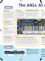 6
6
-
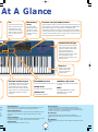 7
7
-
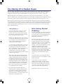 8
8
-
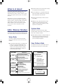 9
9
-
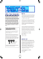 10
10
-
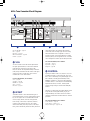 11
11
-
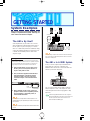 12
12
-
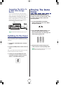 13
13
-
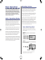 14
14
-
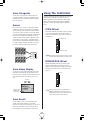 15
15
-
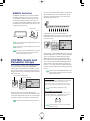 16
16
-
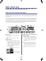 17
17
-
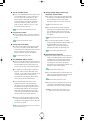 18
18
-
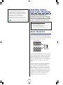 19
19
-
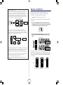 20
20
-
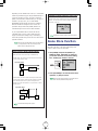 21
21
-
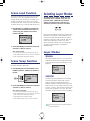 22
22
-
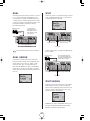 23
23
-
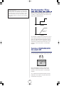 24
24
-
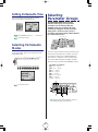 25
25
-
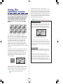 26
26
-
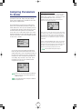 27
27
-
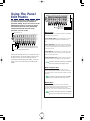 28
28
-
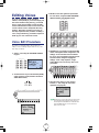 29
29
-
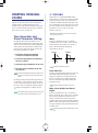 30
30
-
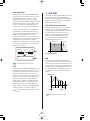 31
31
-
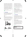 32
32
-
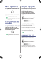 33
33
-
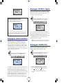 34
34
-
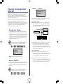 35
35
-
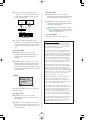 36
36
-
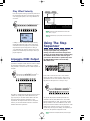 37
37
-
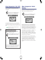 38
38
-
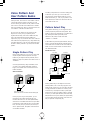 39
39
-
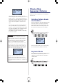 40
40
-
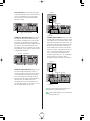 41
41
-
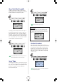 42
42
-
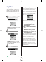 43
43
-
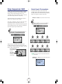 44
44
-
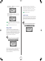 45
45
-
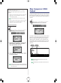 46
46
-
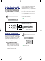 47
47
-
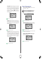 48
48
-
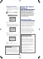 49
49
-
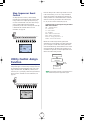 50
50
-
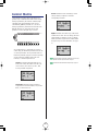 51
51
-
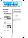 52
52
-
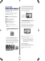 53
53
-
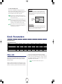 54
54
-
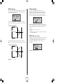 55
55
-
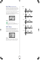 56
56
-
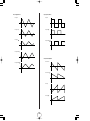 57
57
-
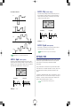 58
58
-
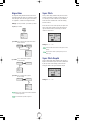 59
59
-
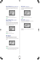 60
60
-
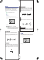 61
61
-
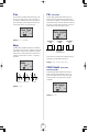 62
62
-
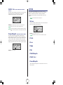 63
63
-
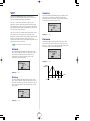 64
64
-
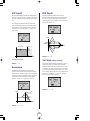 65
65
-
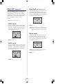 66
66
-
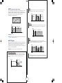 67
67
-
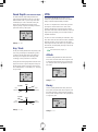 68
68
-
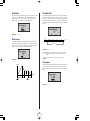 69
69
-
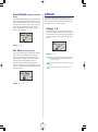 70
70
-
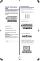 71
71
-
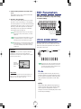 72
72
-
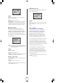 73
73
-
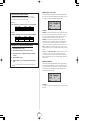 74
74
-
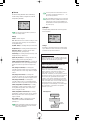 75
75
-
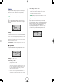 76
76
-
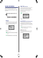 77
77
-
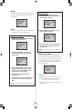 78
78
-
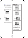 79
79
-
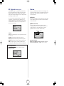 80
80
-
 81
81
-
 82
82
-
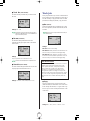 83
83
-
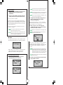 84
84
-
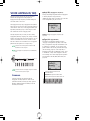 85
85
-
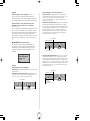 86
86
-
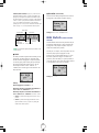 87
87
-
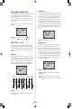 88
88
-
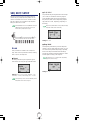 89
89
-
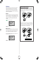 90
90
-
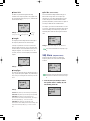 91
91
-
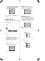 92
92
-
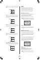 93
93
-
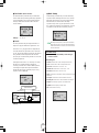 94
94
-
 95
95
-
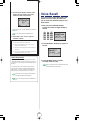 96
96
-
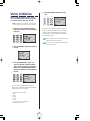 97
97
-
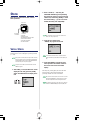 98
98
-
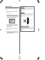 99
99
-
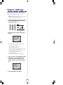 100
100
-
 101
101
-
 102
102
-
 103
103
-
 104
104
-
 105
105
-
 106
106
-
 107
107
-
 108
108
-
 109
109
-
 110
110
-
 111
111
-
 112
112
-
 113
113
-
 114
114
-
 115
115
-
 116
116
-
 117
117
-
 118
118
-
 119
119
-
 120
120
-
 121
121
-
 122
122


diğer dillerde
- español: Yamaha AN1x El manual del propietario
- français: Yamaha AN1x Le manuel du propriétaire
- italiano: Yamaha AN1x Manuale del proprietario
- svenska: Yamaha AN1x Bruksanvisning
- čeština: Yamaha AN1x Návod k obsluze
- polski: Yamaha AN1x Instrukcja obsługi
- Deutsch: Yamaha AN1x Bedienungsanleitung
- português: Yamaha AN1x Manual do proprietário
- English: Yamaha AN1x Owner's manual
- dansk: Yamaha AN1x Brugervejledning
- русский: Yamaha AN1x Инструкция по применению
- suomi: Yamaha AN1x Omistajan opas
- Nederlands: Yamaha AN1x de handleiding
- română: Yamaha AN1x Manualul proprietarului