Yamaha EMX-120CD Kullanım kılavuzu
- Kategori
- Alıcı
- Tip
- Kullanım kılavuzu
Bu kılavuz aynı zamanda aşağıdakiler için de uygundur:

A R
CD CHANGER RECEIVERCD CHANGER RECEIVER
OWNER’S MANUAL
MANUAL DE INSTRUCCIONES
OWNER’S MANUAL
MANUAL DE INSTRUCCIONES
CD CHANGER RECEIVER EMX–120CD
PRESET
/
TUNING
/
BAND
A
/
B
/
C
/
D
/
E
OPEN/CLOSE
DISC
CHANGE
VOLUME
INPUT SELECTOR
VCR • LD/TV • CD • TAPE/MD • TUNER
CD TUNER
STANDBY/ON
PHONES
KARAOKE
PROGRAM
MEMORY
MUSIC
DISPLAY MEMORY AUTO/MAN’L REPEAT TIME
TIME ADJ TIMER HOUR MIN
INPUT TRIM
MIC TONE MIC MIC MIXING
SOFTNORMAL MAXMIN
ECHO ECHO
DISC 1 DISC 2 DISC 3

22
●
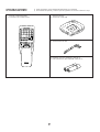
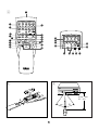
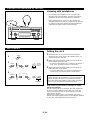
Remote control transmitter
●
Transmisor del control remoto
●
AM loop antenna
●
Antena de cuadro AM
●
Indoor FM antenna
●
Antena interior de FM
●
Batteries (size AA, UM/SUM-3, R6, HP-7)
●
Pilas (tamaño AA, tipo UM/SUM-3, R6, HP-7)
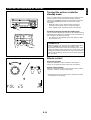
SUPPLIED ACCESSORIES
●
After unpacking, check that the following parts are contained.
ACCESORIOS INCLUIDOS
●
Desembalar el aparato y verificar que los siguientes accesorios están en la caja.
TIME
A
PROG
B C D
+I0
E
CD
TUNER
1
1
2
2
3
3
4
4
5
5
6
6
7
7
8
8
9 0
PRESET
INPUT
MUSIC
PROGRAM
STANDBY/ON
DISPLAY
SLEEP
ECHO
FLAT
LEVEL KARAOKE
VOLUME
DISC SKIP
STOP
PLAY/PAUSE
TUNERCD
TEST
CENTER/REAR
/DELAY
OPEN/CLOSE
REPEAT
RANDOM
MODE

33
CD CHANGER RECEIVER EMX–120CD
PRESET
/
TUNING
/
BAND
A
/
B
/
C
/
D
/
E
OPEN/CLOSE
DISC 1 DISC 2 DISC 3
DISC
CHANGE
VOLUME
INPUT SELECTOR
VCR • LD/TV • CD • TAPE/MD • TUNER
CD TUNER
STANDBY/ON
PHONES
KARAOKE
PROGRAM
MEMORY
ECHO ECHO
MUSIC
DISPLAY MEMORY AUTO/MAN’L REPEAT TIME
TIME ADJ TIMER HOUR MIN
INPUT TRIM
MHz
PRESET
TOTAL REM
NOR TEST
PHANTOM
TIMER
SLEEP
STEREO RANDOM
TUNED MEMORY
AUTO
PROGRAMMUSIC
ROCK POPS
JAZZ USER 12
KARAOKE
L R
VOCAL CUT
PRO LOGIC HALL ARENA DISCO
3 STEREO STADIUM MONO MOVIE
100 1K 10K
VCD
S F REP
PBC
PROG
VOLUME
OVER
1234
78910
13 14 15
5
11
6
12
K
Hz
MIC TONE MIC MIC MIXING
SOFTNORMAL MAXMIN
32 4
87 0 A B C D E F MG H9
5 6
1 2 567 9 B04
C
I
3 8
ED
1
N
A
K LJ
1

44
CD CHANGER RECEIVER EMX–120CD
PRESET
/
TUNING
/
BAND
A
/
B
/
C
/
D
/
E
OPEN/CLOSE
DISC 1 DISC 2 DISC 3
DISC
CHANGE
VOLUME
INPUT SELECTOR
VCR • LD/TV • CD • TAPE/MD • TUNER
CD TUNER
STANDBY/ON
PHONES
KARAOKE
PROGRAM
MEMORY
MUSIC
DISPLAY MEMORY AUTO/MAN’L REPEAT TIME
TIME ADJ TIMER HOUR MIN
INPUT TRIM
MHz
TRACK PRESET
TOTAL REM
NOR TEST
PHANTOM
TIMER
SLEEP
STEREO RANDOM
TUNED MEMORY
AUTO PTY HOLD
PROGRAMMUSIC
ROCK POPS
JAZZ USER 12
PRO LOGIC HALL ARENA DISCO
3 STEREO STADIUM MONO MOVIE
100 1K 10K
S F REP PROG
VOLUME
OVER
1234
78910
13 14 15
5
11
6
12
K
Hz
MIC TONE MIC MIC MIXING
SOFTNORMAL MAXMIN
ECHO ECHO
O
V W
P Q R S T U
F G IH
K ML NJ
2

55
TIME
A
PROG
B C D
+I0
E
CD
TUNER
1
1
2
2
3
3
4
4
5
5
6
6
7
7
8
8
9 0
PRESET
INPUT
MUSIC
PROGRAM
STANDBY/ON
DISPLAY
SLEEP
ECHO
FLAT
LEVEL KARAOKE
VOLUME
DISC SKIP
STOP
PLAY/PAUSE
TUNERCD
TEST
CENTER/REAR
/DELAY
OPEN/CLOSE
REPEAT
RANDOM
MODE
2
1
3
4
A
F
E
C
G
B
D
5
7
8
9
0
6
H
TIME
A
PROG
B C D
+I0
E
CD
TUNER
1
1
2
2
3
3
4
4
5
5
6
6
7
7
8
8
9 0
PRESET
DISC SKIP
STOP
PLAY/PAUSE
OPEN/CLOSE
REPEAT
RANDOM
MODE
I
J
K
L
S
R
ONM P Q
3
1
3
2
4
30°
30°
0.2 m – 6 m
(8” – 20’)
5

66
SPEAKERS
CENTER/REAR
SPEAKERS
FRONT
MAINS
R L
CENTERREAR REAR
REAR SINGLE
CENTER :6
Ω
MIN./SPEAKER
6
Ω
MIN./SPEAKER
SEE OWNER’S MANUAL FOR CONNECTION.
SEE OWNER’S MANUAL FOR CONNECTION.
REAR
:4
Ω
MIN./SPEAKER
REAR SINGLE
:8
Ω
MIN./SPEAKER
RL
L
AUDIO SIGNAL
TAPE
/
MD LD
/
TV
AUDIO SIGNAL
VCR SUBWOOFER
R
IN OUT IN OUT
OUT
VCR MONITOR
OUT
LD
/
TV
VIDEO SIGNAL
ANTENNA
AM
FM
GND
75
Ω
UNBAL.
IN OUT
VIDEO SIGNAL
SUBWOOFER
OUT
OUT
SPEAKERS
CENTER/REAR
SPEAKERS
FRONT
R L
CENTERREAR REAR
REAR SINGLE
CENTER :6
Ω
MIN./SPEAKER
6
Ω
MIN./SPEAKER
SEE OWNER’S MANUAL FOR CONNECTION.
SEE OWNER’S MANUAL FOR CONNECTION.
REAR
:4
Ω
MIN./SPEAKER
REAR SINGLE
:8
Ω
MIN./SPEAKER
RL
50kHz
9kHz
10kHz
100kHz
FM
AM
FREQUENCY
STEP
CENTER
MODE
NORMAL
PHANTOM
AC OUTLET
UNSWITCHED
100W MAX.
VOLTAGE
SELECTOR
L
R
L
R
6
Rear speakers
Altavoces traseros
Center speaker
Altavoz central
Subwoofer system
Sistema de altavoz de
graves secundarios
Front speakers
Altavoces delanteros
EMX-120CD
(General model)
(Modelo General)

77
SPEAKERS
CENTER/REAR
SPEAKERS
FRONT
MAINS
R L
CENTERREAR REAR
REAR SINGLE
CENTER :6
Ω
MIN./SPEAKER
6
Ω
MIN./SPEAKER
SEE OWNER’S MANUAL FOR CONNECTION.
SEE OWNER’S MANUAL FOR CONNECTION.
REAR
:4
Ω
MIN./SPEAKER
REAR SINGLE
:8
Ω
MIN./SPEAKER
RL
L
AUDIO SIGNAL
TAPE
/
MD LD
/
TV
AUDIO SIGNAL
VCR SUBWOOFER
R
IN OUT IN OUT
OUT
VCR MONITOR
OUT
LD
/
TV
VIDEO SIGNAL
ANTENNA
AM
FM
GND
75
Ω
UNBAL.
IN OUT
VIDEO SIGNAL
SPEAKERS
CENTER/REAR
R L
CENTERREAR REAR
REAR SINGLE
CENTER :6
Ω
MIN./SPEAKER
SEE OWNER’S MANUAL FOR CONNECTION.
REAR
:4
Ω
MIN./SPEAKER
REAR SINGLE
:8
Ω
MIN./SPEAKER
50kHz
9kHz
10kHz
100kHz
FM
AM
FREQUENCY
STEP
CENTER
MODE
NORMAL
PHANTOM
AC OUTLET
UNSWITCHED
100W MAX.
VOLTAGE
SELECTOR
L
R
7
White line
Linea blanca
White line
Linea blanca
EMX-120CD
(General model)
(Modelo General)
NX-E70
NX-C70

88
SPEAKERS
CENTER/REAR
SPEAKERS
FRONT
MAINS
R L
CENTERREAR REAR
REAR SINGLE
CENTER :6
Ω
MIN./SPEAKER
6
Ω
MIN./SPEAKER
SEE OWNER’S MANUAL FOR CONNECTION.
SEE OWNER’S MANUAL FOR CONNECTION.
REAR
:4
Ω
MIN./SPEAKER
REAR SINGLE
:8
Ω
MIN./SPEAKER
RL
L
AUDIO SIGNAL
TAPE
/
MD LD
/
TV
AUDIO SIGNAL
VCR SUBWOOFER
R
IN OUT IN OUT
OUT
VCR MONITOR
OUT
LD
/
TV
VIDEO SIGNAL
ANTENNA
AM
FM
GND
75
Ω
UNBAL.
IN OUT
VIDEO SIGNAL
50kHz
9kHz
10kHz
100kHz
FM
AM
FREQUENCY
STEP
CENTER
MODE
NORMAL
PHANTOM
AC OUTLET
UNSWITCHED
100W MAX.
VOLTAGE
SELECTOR
AUDIO OUT
VIDEO OUT
AUDIO OUT
AUDIO IN
VIDEO OUT
VIDEO IN
LINE OUT
LINE IN
VIDEO IN
8
LD player etc.
Tocadiscos de discos láser, etc.
Monitor TV
Monitor de TV
Tape deck, MD recorder, etc.
Platina, grabador de MD, etc.
Video cassette recorder
Videograbador
EMX-120CD
(General model)
(Modelo General)

E-1
English
ENGLISH
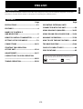
INTRODUCTION
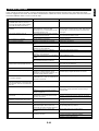
CONTENTS
Page
PRECAUTIONS.............................................2-3
FEATURES.......................................................4
NAMES OF CONTROLS
AND INDICATORS ...........................................5
REMOTE CONTROL TRANSMITTER.............6
SETTING UP THE SPEAKERS ....................7-9
CONNECTIONS ........................................10-12
STARTING THE OPERATION
OF THIS UNIT ...........................................13-14
ADJUSTMENTS........................................14-17
COMPACT DISC PLAYER OPERATION
...................................................................18-25
TUNING OPERATION...............................26-28
Page
OPERATING EXTERNAL UNITS
CONNECTED WITH THIS UNIT.....................29
USING GRAPHIC EQUALIZER................30-32
USING SOUND FIELD PROCESSOR......33-36
KARAOKE OPERATION...........................37-39
HOW TO USE THE BUILT-IN TIMER .......40-42
TROUBLESHOOTING ..............................43-44
CARE OF COMPACT DISCS.........................44
SPECIFICATIONS ..........................................45
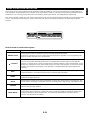
Thank you for purchasing this YAMAHA product. We hope it will give you many years of trouble-free enjoyment. For the best
performance, read this manual carefully. It will guide you in operating your YAMAHA product.
For basic source play, the following illustrations on top of
pages will help you to look for the section you need.
......CD playback ......Tuning

E-2
PRECAUTIONS: READ THIS BEFORE OPERATING YOUR UNIT
■ Be sure to read the “TROUBLESHOOTING” section
regarding common operating errors before concluding that
the unit is faulty.
■ To prevent lightning damage, disconnect the AC power
plug and the antenna cable when there is an electrical
storm.
■ Do not connect audio equipment to the AC outlet on the
rear panel if the equipment requires more power than the
outlet is rated to provide.
■ Do not plug the AC power plug to the wall socket before
you finish all connections.
■ The voltage to be used must be the same as that specified
on this unit. Using this unit with a higher voltage than
specified is dangerous and may result in a fire or other
types of accidents causing damage. YAMAHA will not be
held responsible for any damage resulting from use of this
unit with a voltage other than specified.
■ The sound level at a given volume setting depends on
speaker location and other factors. Care should be taken
to avoid exposure to sudden high levels of sound, which
may occur when turning on the unit with the volume control
setting at high, and to continuous high levels of sound.
■ Sudden temperature changes and storage or operation in
an extremely humid environment may cause condensation
inside the cabinet. Condensation can cause the unit to
malfunction.
To eliminate condensation:
•
CD pickup
Leave the power on with no disc in the unit until normal
playback is possible (about 1 hour).
•
Remote control
Wipe off condensation on the transmitter window with a
soft cloth before operating the unit.
■ To prevent a malfunction of this unit:
•
Do not use any non standard shaped disc (heart etc.)
available on the market, because it may damage the
unit.
•
Do not use a disc with tape, seals, or paste on it,
because damage to the unit may result.
■ To assure the finest performance, please read this manual
carefully. Keep it in a safe place for future reference.
■ Choose the installation location of this unit carefully. Avoid
placing it in direct sunlight or close to a source of heat.
Also avoid locations subject to vibration and excessive
dust, heat, cold or moisture. Keep it away from sources of
hum such as transformers and electric motors.
■ Do not operate this unit upside-down. It may overheat,
possibly causing damage.
■ Never open the cabinet. If something drops into the set,
contact your dealer.
■ The openings on the cabinet assure proper ventilation of
the unit. If these openings are obstructed, the temperature
inside the cabinet will rise rapidly. Therefore, avoid
placing objects against these openings, and install the unit
in well-ventilated condition. Be sure to allow a space of at
least 20 cm behind, 20 cm on the both sides and 30 cm
above the top panel of the unit. Otherwise it may not only
damage the unit, but also cause fire.
■ Always set the VOLUME control to minimum before
starting an audio source play: increase the volume
gradually to an appropriate level after play has started.
■ When not planning to use this unit for long periods of time
(ie., vacation, etc.), disconnect the AC power plug from the
wall outlet.
■ Grounding or polarization – Precautions should be taken
so that the grounding or polarization of the unit is not
defeated.
■ Do not use force on switches, controls or connection wires.
When moving the unit, first disconnect the power plug and
the wires connected to other equipment. Never pull the
wire itself.
■ If an external appliance (TV, radio, etc.) interferes with this
unit’s operation, move this unit away from such an
appliance.
■ Do not attempt to clean the unit with chemical solvents;
this might damage the finish. Use a clean, dry cloth.

WARNING
To reduce the risk of fire or electric shock, do not expose this
unit to rain or moisture.
To avoid electrical shock, do not open the cabinet. Refer
servicing to qualified personnel only.
E-3
English
NOTE
Please check the copyright laws in your country to record
from records, compact discs, radio, etc. Recording of
copyright material may infringe copyright laws.
IMPORTANT
Please record the serial number of this unit in the space
below.
Model:
Serial No.:
The serial number is located on the rear of the unit.
Retain this Owner’s Manual in a safe place for future
reference.
WARNING
TO REDUCE THE RISK OF FIRE OR ELECTRIC SHOCK,
DO NOT EXPOSE THIS APPLIANCE TO RAIN OR
MOISTURE.
CAUTION FOR MOVING THIS UNIT
Before moving this unit, first remove all discs from the disc
table and close the table by pressing the OPEN/CLOSE
button. After you confirm that “NO DISC” lights up on the
display, turn this unit into the standby mode by pressing
the STANDBY/ON switch, and then disconnect the power
plug from the AC outlet.
CAUTION 1
Use of controls or adjustments or performance of
procedures other than those specified herein may result in
hazardous radiation exposure.
CAUTION 2
As the laser beam used in this unit is harmful to the eyes,
do not attempt to disassemble the cabinet. Refer servicing
to qualified personnel only.
Laser component in this product is capable of emitting
radiation exceeding the limit for Class 1.
PRECAUTIONS: READ THIS BEFORE OPERATING YOUR UNIT
This unit is classified as a CLASS 1
LASER product.
The CLASS 1 LASER PRODUCT
label is located on the rear exterior.
Laser Diode Properties
•
Material: GaAlAs
•
Wavelength: 780nm
•
Emission Duration: continuous
•
Laser Output: max. 44.6µW*
* This output is the value measured at a distance of about
200mm from the objective lens surface on the Optical
Pick-up Block.
CLASS 1 LASER PRODUCT
CAUTION FOR CARRYING THIS UNIT
Be sure not to carry or tip this unit with discs remaining in
it.
This unit is not disconnected from the AC power source
as long as it is connected to the wall outlet, even if this
unit itself is turned off. This state is called the standby
mode.
In this state, this unit is designed to consume a certain
level of power.
VOLTAGE SELECTOR (General model only)
The voltage selector on the rear panel of this unit must
be set for your local main voltage BEFORE plugging
into the AC main supply.
Voltages are 110/120/220/240V AC, 50/60 Hz.

E-4
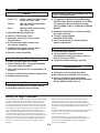
FEATURES
General
● 5-Speaker Configuration
Front L, R: 100W + 100W (6Ω) RMS Output
Power, 10% THD,
1 kHz
Center
: 32W (6Ω) RMS Output Power,
10% THD, 1 kHz
Rear: 28W (8Ω) RMS Output Power,
10% THD, 1 kHz
● Adjustable Display Brightness
● Multi-use Timer/Sleep Timer
● Automatic Turning This Unit into the
Standby Mode
● 4 External Audio/Video Component
Connecting Capability
● SUBWOOFER Output Terminal which
Passes Low Frequencies Only
● Remote Control Capability
Compact Disc Player
● 3-Disc Carousel Type CD Changer
● PLAYXCHANGE; Disc Changing Capability
while Playing Back Another
● 20-Track Random Access Programmable CD
Playback
● Single Track/Entire Disc/All Disc Repeat Play
● Random-sequence Play
Tuner
● 40 Station Random Access Preset Tuning
● 40 Station Automatic Preset Tuning
Sound Field Processor Including Dolby Pro
Logic Surround Decoder
● 2 Programs for Dolby Surround Decoding
(DOLBY PRO LOGIC and DOLBY 3 STEREO)
5 Programs for Sound Field Processing
(HALL, ARENA, DISCO, STADIUM and MONO
MOVIE)
● Automatic Input Balance Control for Dolby
Pro Logic Surround
● 2 Center Channel Modes
(NORMAL/PHANTOM)
● Test Tone Generator for Easier Speaker
Balance Adjustment
Graphic Equalizer
● 3-Band Graphic Equalizer
● 3 Preset Graphic Equalizer Modes
Selectable According to the Music Source
(ROCK, POPS and JAZZ)
● 2 Equalizer Pattern Storing Capability
Karaoke-functions
● 4 Modes for Singing Karaoke
● 2 Microphone Connecting Capability
● MIC Mixing Level and MIC Tone Controls
● Karaoke Sound Recording Capability
(Recording Your Singing Voice and Karaoke
Effects with the Music Source)
This unit employs a Dolby Pro Logic Surround decoder similar
to professional Dolby Stereo decoders used in many movie
theaters. By using the Dolby Pro Logic Surround decoder,
you can experience the dramatic realism and impact of Dolby
Surround movie theater sound in your own home. Dolby Pro
Logic employs a four-channel-five-speaker system. The Pro
Logic Surround system divides the input signal into four
levels: the left and right main channels, the center channel
(used for dialog), and the rear surround sound channels
(used for sound effects, background noise, and other ambient
noises). The center channel allows listeners seated in even
less-than-ideal positions to hear the dialog originating from
the action on the screen while experiencing good stereo
imaging.
Dolby Surround is encoded on the sound track of pre-
recorded video tapes, laser discs, and some TV/cable
broadcasts. When you play a source encoded with Dolby
Surround on this unit, the Dolby Pro Logic Surround decoder
decodes the signal and distributes the surround-sound
effects.
In addition, this unit features a built-in automatic input balance
control. This always assures you the best performance
without manual adjustment.
Manufactured under license from Dolby Laboratories
Licensing Corporation. DOLBY, the double-D symbol and
“PRO LOGIC” are trademarks of Dolby Laboratories
Licensing Corporation.
Dolby Pro Logic Surround

E-5
English
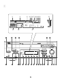
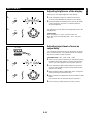
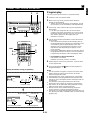
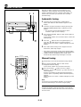
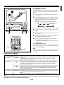
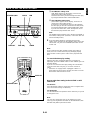
NAMES OF CONTROLS AND INDICATORS
For amplifier/tuner
(See figure 1 on page 33 at the beginning part of this
manual.)
Display
1 Preset Equalizer Mode Indicator (MUSIC)
2 Sound Field Program Indicator (PROGRAM)
3 Karaoke Mode Indicator (KARAOKE)
4 Center Channel Mode (NOR/PHANTOM) Indicator
5 TEST Indicator
6 TIMER Set Indicator
7 STEREO Indicator
8 TUNED Indicator
9 MEMORY Indicator
0 AUTO Tuning Indicator
A SLEEP Indicator
B Volume Level Meter (VOLUME)
C Graphic Equalizer Level Indicators
D Preset Number Indicator (PRESET)
E Multi Information Display
(Time, Station Frequency, Volume Level, etc.)
1 STANDBY/ON Switch
2 PROGRAM Selector Button
3 Equalizer Control Buttons
(ECHO Buttons)
4 MUSIC Button
5 A/B/C/D/E Button
6 PRESET/TUNING/BAND Selector Button
7 PHONES Jack
8 KARAOKE Button
9 User Program MEMORY Button
0 Remote Control Sensor
A DISPLAY Button
B Tuner MEMORY (TIME ADJUST) Button
C AUTO/MAN’L (TIMER) Button
D REPEAT (HOUR) Button
E TIME (MIN) Button
F INPUT TRIM Button
G CD INPUT SELECTOR Button
H TUNER INPUT SELECTOR Button
I INPUT SELECTOR (Down)/ (Up) Buttons
J MIC TONE (Microphone Tone) Control
K MIC (Microphone) Jacks
L MIC MIXING (Microphone Mixing) Level Control
M VOLUME Control
N
Tuning (Down)/ (Up) Buttons
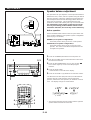
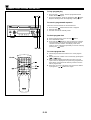
For CD player
(See figure 2 on page 44 at the beginning part of this
manual.)
Display
F RANDOM Play Indicator
G Music Calendar Indicator
H Music Calendar OVER Indicator
I Disc Indicator
J Track Number Indicator (TRACK)
K Time Display
L Play Indicator:
M (S, F) REPEAT Indicator
N Program (PROG) Play Indicator
O Disc Table
P DISC Selector Buttons
Q OPEN/CLOSE Button:
R DISC CHANGE Button
S Stop Button:
T Play/Pause Button: /
U Skip Buttons: /
(Search Buttons: / )
V REPEAT Button
W TIME Button

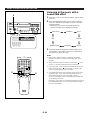
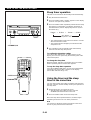
E-6
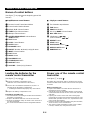
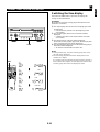
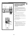
Loading the batteries for the
remote control transmitter
(See figure 4 on page 55.)
1 Remove the battery compartment cover.
(Slide the cover in the direction of the arrow.)
2 Insert 2 “AA” size batteries (UM/SUM-3, R6, HP-7 or
equivalent) into the battery compartment.
* Installing the batteries improperly may cause failure.
3 Replace the battery compartment cover.
Precautions for battery use
•
Insert the batteries according to the direction indicated in
the battery compartment.
•
Replace all batteries with new ones at the same time.
•
Remove the batteries if they are weak or the unit is not in
use for long periods.
•
Do not mix normal batteries with rechargeable batteries.
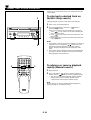
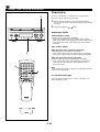
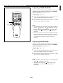
Proper use of the remote control
transmitter
(See figure 5 on page 55.)
Aim (within the range of 60° with no obstacles) the remote
control transmitter at the remote control sensor and operate
as shown.
Notes concerning use
•
Replace the batteries if control distance decreases or
operation becomes unstable.
•
Periodically clean the transmitter window on the remote
control transmitter and the sensor on the main unit with a
soft cloth.
•
Exposing the sensor on the main unit to strong light
(especially an inverter type of fluorescent lamp etc.) may
interfere with operation. In this case, reposition the main
unit to avoid direct lighting.
•
Keep the remote control transmitter away from moisture,
excessive heat, shock and vibrations.
•
The remote control transmitter’s usable range is within
0.2m (8”) and 6m (20’) away from the sensor.
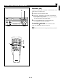
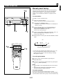
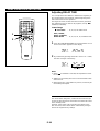
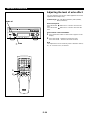
Names of control buttons
(See figure 3 on page 55 at the beginning part of this
manual.)
■
Amplifier/tuner control buttons
1 Remote Control Transmitter Window
2 Preset Station Number Buttons
3 A, B, C, D, E Selector Buttons
4 TUNER Input Selector Button
5 CD Input Selector Button
6 CENTER/REAR/DELAY Selector Button
(ECHO Button)
7 TEST Button
8 LEVEL Control Buttons
9 SLEEP Button
0 KARAOKE Button
A PRESET Number (Down)/ (Up) Buttons
B INPUT Selector Buttons
C FLAT Button
D MUSIC Button
E PROGRAM Button
F STANDBY/ON Switch
G DISPLAY Button
H VOLUME – (Down)/+ (Up) Buttons
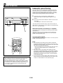
■ CD player control buttons
I Track Number Input Buttons
J TIME Button
K PROGRAM Button
L Disc Play MODE Selector Button
M DISC SKIP Button
N Skip Buttons: /
(Search Buttons: / )
O REPEAT Button
P STOP Button:
Q PLAY/PAUSE Button:
R OPEN/CLOSE Button:
S RANDOM Button
REMOTE CONTROL TRANSMITTER

E-7
English
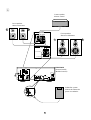
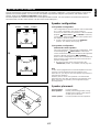
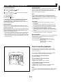
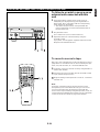
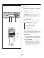
SETTING UP THE SPEAKERS
This unit is designed to provide the best sound-field quality with a 5-speaker configuration: a pair of front speakers, a pair of rear
speakers and a center speaker. You can use one rear speaker only instead of using two rear speakers, and omit the center
speaker. (Refer to the
“Speaker configuration” shown below.)
The front speakers are used for the main source sound plus the effect sounds. The rear speakers are used for the effect and
surround sounds, and the center speaker is for the center sounds (dialog etc.).
(1)
(2)
Front R
Center
Front L
TV set
Rear R
Rear L
Speaker configuration
(1)5-Speaker Configuration
This configuration is the most effective and recommended
one. In this configuration, the center speaker is
necessary as well as the rear speakers. If the sound field
program PRO LOGIC or 3 STEREO is selected,
conversations will be output from the center speaker and
the ambience will be excellent.
● Set the center channel mode to the “NORMAL”
position. (For details, refer to page 16.)
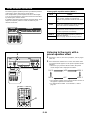
(2)4-Speaker Configuration
(without the center speaker)
The center speaker is not used in this configuration. If the
sound field program PRO LOGIC is selected, the
center sound will be output from the left and the right front
speakers, although the program 3 STEREO is
useless in this configuration. However, the sound effect of
other programs can be almost the same as that of the 5-
speaker configuration.
● Be sure to set the center channel mode to the
“PHANTOM” position. (For details, refer to page 16.)
Note
As this unit is equipped with a monaural amplifier for the rear
channel, sounds output from the rear speakers are in
monaural. So, you may use one rear speaker only instead of
using two rear speakers.
However, the use of two rear speakers is recommended
when there are more than one listener in the listening room.
When using one rear speaker, place it right behind your
listening position.
Speaker placement
Front speakers: In normal position.
Rear speakers: Behind your listening position, facing
slightly inward. Nearly 1.8 m (approx.
six feet) up from the floor.
Center speaker: Precisely between the front speakers.
Rear L
TV set
Rear R
Front L Center Front R
Dialogue
Surround sound
Dialogue
Surround sound
Rear L
Rear R
Front L Front R
Dialogue
Surround sound
Dialogue
Surround sound
Rear L Rear R
Front L
Front R
Center

E-8
SETTING UP THE SPEAKERS
40mm
1
2
Good No good
Tapping screw
(Available at the
hardware store)
Wall/ wall
support
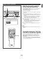
Only for customers who use the YAMAHA
NS-P30 speaker system (separate
purchase)
If you use the YAMAHA NS-P30 speaker system with this
unit, read the following descriptions for mounting the NS-P30.
* “NS-P30” is the package number which includes the
YAMAHA speaker systems NX-E70 and NX-C70.
NX-E70 is designed to be used as a rear effect speaker
system, and NX-C70 is designed to be used as a center
speaker system.
■ Mounting the rear speakers (NX-E70)
Mount the rear speakers on a shelf, rack or on the floor
directly, or hang them on the wall.
To mount the rear speakers on a wall
1 Attach the provided mounting bracket to the rear of the
speaker by using the provided screws.
2 Fasten screws into a firm wall or wall support as shown in
the diagram, and hang the holes of the mounting bracket
on the protruding screws.
* The holes are arranged so that the speakers can be
mounted in a side long, upright or upside-down way.
* Make sure that the screws are caught by a narrow part
of the holes securely.
Notes
●
Never attach the bracket to the speaker backwards.
●
Speaker cords should be connected to the speaker’s
terminals after the bracket is attached to the speaker to
prevent the speaker cords pressed between the speaker
and the bracket.

E-9
English
WARNING:
●
Each speaker weighs 0.8 kg (1 lbs. 12 oz.). Do not
mount them on thin plywood or soft wall surface
material, as the screws may come out of the flimsy
surface, causing the speakers to fall down and be
damaged, or result in personal injury.
●
Do not fasten the speakers to wall with nails,
adhesives, or other unsound hardware. Long-term use
and vibrations may cause them to fall down.
●
To avoid accidents resulting from tripping over loose
speaker cables, fix them to the wall.
To hang in a side long way
Hang the speakers so that each of them faces inside as
figured left.
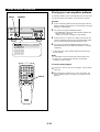
SETTING UP THE SPEAKERS
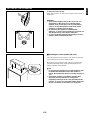
■
Mounting the center speaker (NX-C70)
Place the speaker on top of the TV or on the floor under the
TV or inside the TV rack in a stable position.
When placing the speaker on top of the TV, to prevent the
speaker from falling down, put the provided pads at four
points on bottom of the speaker.
Notes
●
Do not place the speaker on top of the TV whose area
is smaller than the bottom area of the speaker. If
placed, the speaker may drop out causing an injury to
you.
●
Though this speaker is a magnetic shielding type,
there may be some influence on a TV picture
depending on the type of TV or the placement of the
speaker. In such a case, place the speaker apart from
the TV so that there is no influence on TV picture.

E-10
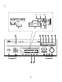
CONNECTIONS
Connecting speakers
(See figure 6 on page 66.)
Connect the front speakers to the FRONT SPEAKERS
terminals, the center speaker to the CENTER SPEAKERS
terminals and the rear speakers to the REAR SPEAKERS
terminals.
Note
Use speakers with the specified impedance shown on the
rear of this unit.
n
How to Connect:
Connect the SPEAKERS terminals to your speakers with wire
of the proper gauge, cut as short as possible. If the
connections are faulty, no sound will be heard from the
speakers. Make sure that the polarity of the speaker wires is
correct, that is the + and – markings are observed. If these
wires are reversed, the sound will be unnatural and lack bass.
Caution
Do not let the bare speaker wires touch each other as
this could damage the amplifier and/or speakers.
Note on connecting one rear speaker only
You can use one rear speaker only in place of two rear
speakers. For connecting one rear speaker, follow the
method shown below.
Note on connecting a subwoofer (separate
purchase)
You may wish to add a subwoofer to reinforce the bass
frequencies.
Connect the SUBWOOFER OUT terminal of this unit to the
INPUT terminal of the subwoofer amplifier, and connect the
speaker terminals of the subwoofer amplifier to the
subwoofer.
With some subwoofer systems, including the Yamaha Active
Servo Processing Subwoofer System, an amplifier is
incorporated into the system.
* The SUBWOOFER OUT terminal outputs low frequencies
from the front and center channels.
(The cut-off frequency of signals output from this terminal is
200 Hz.)
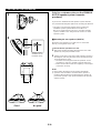
n
How to connect the YAMAHA NS-P30 speaker
system (separate purchase) to this unit
(See figure 7 on page 77.)
If you connect the YAMAHA NS-P30 speaker system to this
unit, read the following descriptions.
NX-E70 (Rear speakers)
● Connect the push-type input terminals on the rear of the
speakers to the REAR SPEAKERS terminals of this unit
with the provided speaker cables.
● One side of the speaker cable has a white line and the
other side has no line. Connect the (+) terminals on both
this unit and the speakers using the side with a white line.
Connect the (–) terminals on both components using the
side with no line.
● Connect one speaker to the left (marked L) terminals of
this unit, and another speaker to the right (marked R)
terminals, making sure not to reverse the polarity (+, –). If
one speaker is connected with reversed polarity, the sound
will be unnatural and lack bass.
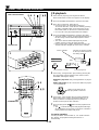
Procedures:
➀ Press the tab on the terminal down, as shown in the
figure.
➁ Insert the bare speaker wire end properly into the terminal
hole. [Remove approx. 5 mm (1/4”) insulation from the
speaker cable.]
➂ Remove your finger from the tab to allow it to lock snugly
on the cable’s wire end.
➃ Test the security of the connection by tugging lightly on
the cable at the terminal.
NX-C70 (Center speaker)
To connect the speaker cable from NX-C70 to the CENTER
SPEAKERS terminals of this unit, make sure to connect the
side with a white line to the (+) terminal and the side with no
line to the (–) terminal.
Red: positive (+)
Black: negative (–)
➀
Press up the tab.
➁
Insert the bare wire.
[Remove approx.
5mm (1/4”) insulation
from the speaker
wires.]
➂
Press down the tab
and secure the wire.
➀
➁
➂
Never plug the AC supply lead of this unit into the AC outlet until all connections are
completed.
R L
CENTERREAR REAR
REAR SINGLE
Rear speaker

E-11
English
ANTENNA
AM
FM
GND
75
Ω
UNBAL.
ANTENNA
AM
FM
GND
75
Ω
UNBAL.
(1)
(2)
(3)
(4)
ANTENNA
AM
FM
GND
75
Ω
UNBAL.
VCR MONITOR
OUT
ANTENNA
AM
FM
GND
75
Ω
UNBAL.
N
OUT
E
O SIGNAL
50kHz
9kH
100kHz
FM
FREQUENCY
STEP
CENTER
MODE
NORMAL
PHANTOM
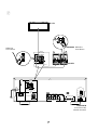
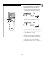
Antenna connection
(1) Supplied FM antenna
Connect the FM antenna wire to the corresponding terminal
and direct the FM antenna wire to the direction where the
strongest signal can be received.
(2) Supplied AM loop antenna
Connect the AM loop antenna wires to the corresponding
terminals. Position the AM loop antenna for optimum
reception. Place the AM loop antenna on a shelf etc., or
install it on the rack or wall with screws (not supplied).
Notes
•
When static is still heard even after adjusting the position
of the AM loop antenna, try reversing the wire connections
(from the upper terminal to the lower one, and vice versa).
•
Do not place the AM loop antenna on the unit. It will result
in noise generation, since the unit is equipped with digital
electronics. Place the AM loop antenna away from the
unit.
(3) External FM antenna
Use an external FM antenna instead of an indoor FM
antenna if you need better reception. Consult your dealer.
(4) External AM antenna
Use an external AM antenna if you need better reception.
Consult your dealer.
Note
When using an external AM antenna, be sure to keep the
wire of the AM loop antenna connected.
CONNECTIONS
or
15 m (49 feet)
7.5 m (25 feet)
Earth rod
FREQUENCY STEP switch (General model only)
Because the interstation frequency spacing differs in
different areas, set the FREQUENCY STEP switch
(located at the rear) according to the frequency spacing in
your area. Before setting this switch, disconnect the AC
supply lead of this unit from the AC outlet.

E-12
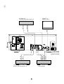
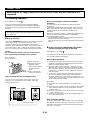
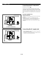
CONNECTIONS
Connecting external components
(See figure 8 on page 88.)
This unit can be connected with external audio and video
components. Make connections between this unit and other
components using RCA pin plug connector cables correctly,
that is to say L (left) to L and R (right) to R. Also, refer to the
owner’s manual for each component to be connected to this
unit.
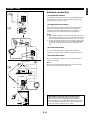
AC OUTLET (UNSWITCHED)
(General model only)
The power cord of any audio/video unit can be connected to
this outlet.
The power to this outlet is not controlled by this unit’s
STANDBY/ON switch . This outlet will supply power to the
connected unit even if this unit is in the standby mode.
The maximum power that can be connected to this outlet is
100 watts
Connecting the AC supply lead
•
After completing all connections, plug the AC supply lead
into a convenient AC outlet.
•
Unplug the AC supply lead from the AC outlet if the unit is
not to be used for a long period of time.
SPEAKERS
CENTER/REAR
SPEAKERS
FRONT
MAINS
R L
CENTERREAR REAR
REAR SINGLE
CENTER :6
Ω
MIN./SPEAKER
6
Ω
MIN./SPEAKER
SEE OWNER’S MANUAL FOR CONNECTION.
SEE OWNER’S MANUAL FOR CONNECTION.
REAR
:4
Ω
MIN./SPEAKER
REAR SINGLE
:8
Ω
MIN./SPEAKER
RL
L
TAPE
/
MD
R
IN OUT
AC OUTLET
UNSWITCHED
100W MAX.
VOLTAGE
SELECTOR
To AC outlet
SPEAKERS
CENTER/REAR
SPEAKERS
FRONT
MAINS
R L
CENTERREAR REAR
REAR SINGLE
CENTER :6
Ω
MIN./SPEAKER
6
Ω
MIN./SPEAKER
SEE OWNER’S MANUAL FOR CONNECTION.
SEE OWNER’S MANUAL FOR CONNECTION.
REAR
:4
Ω
MIN./SPEAKER
REAR SINGLE
:8
Ω
MIN./SPEAKER
RL
L
TAPE
/
MD
R
IN OUT
AC OUTLET
UNSWITCHED
100W MAX.
VOLTAGE
SELECTOR
AC OUTLET (UNSWITCHED)
(General model)
(General model)
Sayfa yükleniyor...
Sayfa yükleniyor...
Sayfa yükleniyor...
Sayfa yükleniyor...
Sayfa yükleniyor...
Sayfa yükleniyor...
Sayfa yükleniyor...
Sayfa yükleniyor...
Sayfa yükleniyor...
Sayfa yükleniyor...
Sayfa yükleniyor...
Sayfa yükleniyor...
Sayfa yükleniyor...
Sayfa yükleniyor...
Sayfa yükleniyor...
Sayfa yükleniyor...
Sayfa yükleniyor...
Sayfa yükleniyor...
Sayfa yükleniyor...
Sayfa yükleniyor...
Sayfa yükleniyor...
Sayfa yükleniyor...
Sayfa yükleniyor...
Sayfa yükleniyor...
Sayfa yükleniyor...
Sayfa yükleniyor...
Sayfa yükleniyor...
Sayfa yükleniyor...
Sayfa yükleniyor...
Sayfa yükleniyor...
Sayfa yükleniyor...
Sayfa yükleniyor...
Sayfa yükleniyor...
-
 1
1
-
 2
2
-
 3
3
-
 4
4
-
 5
5
-
 6
6
-
 7
7
-
 8
8
-
 9
9
-
 10
10
-
 11
11
-
 12
12
-
 13
13
-
 14
14
-
 15
15
-
 16
16
-
 17
17
-
 18
18
-
 19
19
-
 20
20
-
 21
21
-
 22
22
-
 23
23
-
 24
24
-
 25
25
-
 26
26
-
 27
27
-
 28
28
-
 29
29
-
 30
30
-
 31
31
-
 32
32
-
 33
33
-
 34
34
-
 35
35
-
 36
36
-
 37
37
-
 38
38
-
 39
39
-
 40
40
-
 41
41
-
 42
42
-
 43
43
-
 44
44
-
 45
45
-
 46
46
-
 47
47
-
 48
48
-
 49
49
-
 50
50
-
 51
51
-
 52
52
-
 53
53


Yamaha EMX-120CD Kullanım kılavuzu
- Kategori
- Alıcı
- Tip
- Kullanım kılavuzu
- Bu kılavuz aynı zamanda aşağıdakiler için de uygundur:
diğer dillerde
- español: Yamaha EMX-120CD Manual de usuario
- français: Yamaha EMX-120CD Manuel utilisateur
- italiano: Yamaha EMX-120CD Manuale utente
- svenska: Yamaha EMX-120CD Användarmanual
- čeština: Yamaha EMX-120CD Uživatelský manuál
- polski: Yamaha EMX-120CD Instrukcja obsługi
- Deutsch: Yamaha EMX-120CD Benutzerhandbuch
- português: Yamaha EMX-120CD Manual do usuário
- English: Yamaha EMX-120CD User manual
- dansk: Yamaha EMX-120CD Brugermanual
- русский: Yamaha EMX-120CD Руководство пользователя
- suomi: Yamaha EMX-120CD Ohjekirja
- Nederlands: Yamaha EMX-120CD Handleiding
- română: Yamaha EMX-120CD Manual de utilizare
İlgili makaleler
-
Yamaha EMX-100CD Kullanım kılavuzu
-
-
-
-
-
-
-
-
-