
NS-SW901
SUBWOOFER
CAISSON DE GRAVE
G
OWNER’S MANUAL
MODE D’EMPLOI
BEDIENUNGSANLEITUNG
BRUKSANVISNING
MANUALE DI ISTRUZIONI
MANUAL DE INSTRUCCIONES
GEBRUIKSAANWIJZING
ИНСТРУКЦИЯ ПО ЭКСПЛУАТАЦИИ

i En
Thank you for selecting this Yamaha product.
Please read the following operating precautions before use.
Yamaha will not be held responsible for any damage and/or injury
caused by not following the cautions below.
• To assure the finest performance, please read this manual
carefully. Keep it in a safe place for future reference.
• Install this unit in a cool, dry, clean place - away from
windows, heat sources, sources of excessive vibration, dust,
moisture and cold. Avoid sources of humming (transformers,
motors). To prevent fire or electrical shock, do not expose this
unit to rain or water.
• The voltage to be used must be the same as that specified on the
rear panel. Using this unit with a higher voltage than specified
is dangerous and may cause a fire and/or electric shock.
• Do not use force on switches, controls or connection wires.
When moving the unit, first disconnect the power plug and the
wires connected to other equipments. Never pull the wires
themselves.
• When not planning to use this unit for a long period (ie.,
vacation, etc.), disconnect the AC power plug from the wall
outlet.
• Since this unit has a built-in power amplifier, heat will radiate
from the rear panel. Place the unit apart from the walls,
allowing at least 20 cm of space above, behind and on both
sides of the unit to prevent fire or damage. Furthermore, do not
position with the rear panel facing down on the floor or other
surfaces.
• Do not cover the rear panel of this unit with a newspaper, a
tablecloth, a curtain, etc. in order not to obstruct heat radiation.
If the temperature inside the unit rises, it may cause fire,
damage to the unit and/or personal injury.
• Do not place the following objects on this unit:
- Glass, china, small metallic etc.
If glass etc. falls by vibrations and breaks, it may cause bodily
injury.
- A burning candle etc.
If the candle falls by vibrations, it may cause fire and bodily
injury.
- A vessel with water in it
If the vessel falls by vibrations and water spills, it may cause
damage to the speaker, and/or you may get an electric shock.
• Do not place this unit where foreign objects such as water drips
might fall. It might cause a fire, damage to this unit, and/or
personal injury.
• Never put a hand or a foreign object into the YST port located
on the front side of this unit. When moving this unit, do not
hold the port as it might cause personal injury and/or damage
to this unit.
• Never place a fragile object near the YST port of this unit. If
the object falls or drops by the air pressure, it may cause
damage to the unit and/or personal injury.
• Never open the cabinet. It might cause an electric shock, since
this unit uses a high voltage. It might also cause personal injury
and/or damage to this unit. If something drops into the set,
contact your dealer.
• When using a humidifier, be sure to avoid condensation inside
this unit by allowing enough spaces around this unit or
avoiding excess humidification. Condensation might cause a
fire, damage to this unit, and/or electric shock.
• Super-bass frequencies reproduced by this unit may cause a
turntable to generate a howling sound. In such a case, move
this unit away from the turntable.
• This unit may be damaged if certain sounds are continuously
output at high volume level. For example, if 20 Hz-50 Hz sine
waves from a test disc, bass sounds from electronic
instruments, etc. are continuously output, or when the stylus of
a turntable touches the surface of a disc, reduce the volume
level to prevent this unit from being damaged.
• If you hear distorted noise (i.e., unnatural, intermittent
“rapping” or “hammering” sounds) coming from this unit,
reduce the volume level. Extremely loud playing of a movie
soundtrack’s low frequency, bass-heavy sounds or similarly
loud popular music passages can damage this speaker system.
• Vibration generated by super-bass frequencies may distort
images on a TV. In such a case, move this unit away from the
TV set.
• Do not attempt to clean this unit with chemical solvents as this
might damage the finish. Use a clean, dry cloth.
• Be sure to read the “TROUBLESHOOTING” section
regarding common operating errors before concluding that the
unit is faulty.
• Install this unit near the wall outlet and where the AC power
plug can be reached easily.
• The batteries shall not be exposed to excessive heat such as
sunshine, fire or the like.
- Keep the batteries in a location out of reach of children.
Batteries can be dangerous if a child were to put in his or her
m
outh
.
- If the batteries grow old, the effective operation range of the
remote control decreases considerably. If this happens,
replace the batteries with new one as soon as possible.
- Do not use old batteries together with new ones.
- Do not use different types of batteries (such as alkalineand
manganese batteries) together. Read the packaging carefully
as these different types of batteries may have the same shape
and color.
- Exhausted batteries may leak. If the batteries have leaked,
dispose of them immediately. Avoid touching the leaked
material or letting it come into contact with clothing, etc.
Clean the battery compartment thoroughly before installing
new batteries.
- If you plan not to use the unit for a long period of time,
remove the batteries from the unit. Otherwise, the batteries
will wear out, possibly resulting in a leakage of battery liquid
that may damage the unit.
- Do not throw away batteries with general house waste.
Dispose of them correctly in accordance with your local
regulations.
• Secure placement or installation is the owner’s
responsibility. Yamaha shall not be liable for any accident
caused by improper placement or installation of speakers.
CAUTION: Read this before operating your unit.
CAUTION
Danger of explosion if battery is incorrectly replaced. Replace
only with the same or equivalent type.
WARNING
TO REDUCE THE RISK OF FIRE OR ELECTRIC SHOCK,
DO NOT EXPOSE THIS APPLIANCE TO RAIN OR
MOISTURE.

ii En
English
• VOLTAGE SELECTOR
(Asia and General models only)
The voltage selector switch on the rear panel of this unit
must be set for your local main voltage BEFORE plugging
this unit into the AC main supply. Voltages are 110/120/
220/230-240 V AC, 50/60 Hz.
For U.K. customers
If the socket outlets in the home are not suitable for the plug
supplied with this appliance, it should be cut off and an
appropriate 3 pin plug fitted. For details, refer to the instructions
described below.
Note: The plug severed from the mains lead must be destroyed, as
a plug with bared flexible cord is hazardous if engaged in a live
socket outlet.
SPECIAL INSTRUCTIONS FOR U.K. MODEL
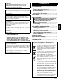
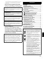
GETTING STARTED ............................................. 1
Features ........................................................................ 1
About this manual ....................................................... 1
Supplied accessories................................................... 1
Controls and functions ................................................ 2
Preparing the remote control ...................................... 4
PLACEMENT ........................................................ 5
Subwoofer orientation ................................................. 5
CONNECTIONS .................................................... 6
Connecting to the amplifier equipped
with subwoofer (line out) terminal(s)..........................6
Connecting to an amplifier not equipped
with a subwoofer (line out) terminal
.............................. 8
Connecting to the ground terminal........................... 11
Connecting the power cable...................................... 11
USING THIS UNIT ............................................... 12
Adjusting the sound balance .................................... 12
Storing the sound balance settings.......................... 13
Setting the sleep timer ............................................... 13
Operating the power of this unit using
the remote control of your amplifier......................... 14
Frequency response .................................................. 15
Advanced Yamaha
Active Servo Technology II................................ 16
TROUBLESHOOTING ........................................ 17
SPECIFICATIONS .............................................. 18
This unit features a magnetically shielded design, but there is
still a chance that placing it too close to a TV set might impair
picture color. Should this happen, move this unit away from the
TV set.
This unit is not disconnected from the AC power source as
long as it is connected to the wall outlet, even if this unit
itself is turned off. In this state, this unit is designed to
consume a very small quantity of power.
IMPORTANT:
THE WIRES IN MAINS LEAD ARE COLOURED IN
ACCORDANCE WITH THE FOLLOWING CODE:
Blue: NEUTRAL
Brown: LIVE
As the colours of the wires in the mains lead of this
apparatus may not correspond with the coloured markings
identifying the terminals in your plug, proceed as follows:
The wire which is coloured BLUE must be connected to
the terminal which is marked with the letter N or coloured
BLACK. The wire which is coloured BROWN must be
connected to the terminal which is marked with the letter L
or coloured RED. Making sure that neither core is
connected to the earth terminal of the three pin plug.
Taking care of the speaker
To maintain the spotless glossy surface of the polished finish,
wipe it with a soft, dry cloth. To avoid damage to the finish, do
not apply chemical solvents, such as alcohol, benzine, thinner,
insecticide, etc. Also, do not use a damp cloth, or any type of
cloth that contains chemical solvents, or place a plastic or
vinyl sheet on top of the speaker.
Otherwise, the finish may peel, the color may fade, or the
sheet may stick to the surface.
CONTENTS
Information for Users on Collection and Disposal
of Old Equipment and Used Batteries
These symbols on the products, packaging, and/or
accompanying documents mean that used electrical
and electronic products and batteries should not be
mixed with general household waste.
For proper treatment, recovery and recycling of old
products and used batteries, please take them to
applicable collection points, in accordance with your
national legislation and the Directives 2002/96/EC
and 2006/66/EC.
By disposing of these products and batteries
correctly, you will help to save valuable resources
and prevent any potential negative effects on human
health and the environment which could otherwise
arise from inappropriate waste handling.
For more information about collection and recycling
of old products and batteries, please contact your
local municipality, your waste disposal service or the
point of sale where you purchased the items.
[Information on Disposal in other Countries
outside the European Union]
These symbols are only valid in the European Union. If you
wish to discard these items, please contact your local
authorities or dealer and ask for the correct method of disposal.
Note for the battery symbol (bottom two
symbol examples):
This symbol might be used in combination with a chemical
symbol. In this case it complies with the requirement set by
the Directive for the chemical involved.
1
2

1 En
3
◆ High 600 W dynamic power
◆ L.F.E input terminal
◆ Sleep timer
◆ Remote control capability
You can make setting changes and adjustments for this
unit by using the remote control from your listening
position.
◆ Advanced Yamaha Active Servo Technology II
This unit employs Advanced Yamaha Active Servo
Technology II which Yamaha has developed for
reproducing higher quality super-bass sound.
◆ Two input connections
This unit can be easily added to your existing audio
system by connecting to either the speaker terminals or
the line output (pin jack) terminals of the amplifier.
◆ Optimum bass sounds with various settings
Setting high cut and phase keeps the optimum sound
quality balance between the front speakers and this unit.
◆ B.A.S.S. mode button
This unit is equipped with the B.A.S.S. mode button so
that you can enjoy bass sound that matches any kind of
source.
• In this manual, operations that can be performed using either the front panel of this unit or the remote control are
explained using the remote control.
• y indicates a tip for your operation.
• Notes contain important information about safety and operating instructions.
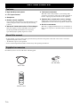
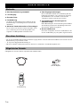
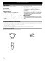
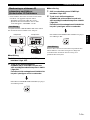
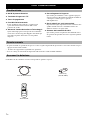
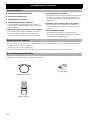
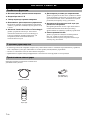
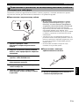
Check that you have received all of the following parts.
GETTING STARTED
Features
About this manual
Supplied accessories
Power cable
POWER
STANDBY
SLEEP
PHASE
MEMORY
PRESET
HIGH CUT
VOLUME
213
B.A.S.S.
Remote control
Batteries (2)
(AA, R6, UM-3)

2 En
GETTING STARTED
English
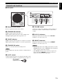
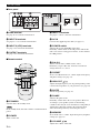
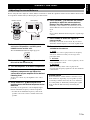
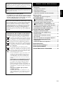
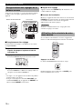
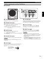
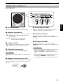
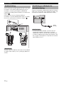
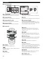
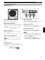
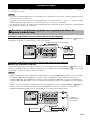
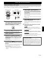
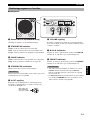
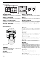
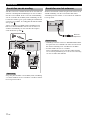
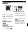
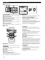
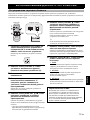
■ Front panel
Remote control sensor
Receives signals from the remote control.
STANDBY/ON indicator
Green: Lights up when this unit is on.
Red: Lights up when this unit is in the standby mode.
Orange: Lights up when the sleep timer is on.
PHASE indicator
Green
: Lights up when the phase is set in the reverse mode.
Red: Lights up when the phase is set in the regular mode.
STANDBY/ON switch
Turns on or sets this unit to the standby mode.
In the standby mode, this unit consumes a small amount of
power.
H-CUT control
Adjusts the high frequency cut off point depending on the
connected front speakers or your preference (see page 12).
VOLUME control
Adjusts the volume level. Turn the control clockwise to
increase the volume, counterclockwise to decrease the
volume.
B.A.S.S. indicators
Light up to indicate the currently selected B.A.S.S.
number (1, 2 or 3) (see page 12).
PRESET indicators
Light up to indicate the currently selected PRESET
number (1, 2 or 3) (see page 13).
• If you set this unit to the standby mode when one of the
PRESET indicators is lit, no PRESET indicator lights up
when you turn on this unit next time.
• The PRESET indicator turns off when you press any
button other than PRESET 1, 2, or 3, or when you
operate any other function of this unit.
Controls and functions
H-CUT
SUBWOOFER SYSTEM NS-SW901
STANDBY
/ON
STANDBY
/ON
PHASE
123123
B.A.S.S.
PRESET
140Hz
40Hz
VOLUME
10
0
Note
H-CUT
140Hz
40Hz
One graduation
of this control
represents 10 Hz.
Notes

3 En
GETTING STARTED
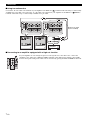
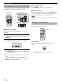
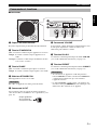
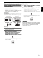
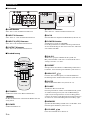
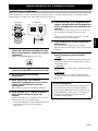
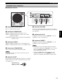
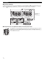
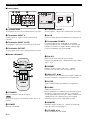
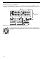
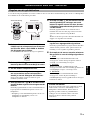
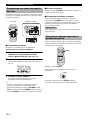
■Rear panel
GND terminal
See page 11 for connection information.
INPUT 3 terminals
See pages 6 - 7 for connection information.
INPUT 2 (LFE) terminals
See page 7 for connection information.
OUTPUT terminals
See page 9 for connection information.
INPUT 1 terminals
See pages 9 - 10 for connection information.
AC IN
Connects the supplied power cable (see page 11).
POWER switch
Switches the power (ON/OFF) of this unit.
Normally, set this switch to the ON position. When this
unit is not used for a long period of time, set the switch to
the OFF position.
■Remote control
STANDBY
Sets this unit to the standby mode.
In the standby mode, this unit consumes a small amount of
power.
POWER
Turns on this unit.
B.A.S.S.
Selects a mode that is suitable for the source.
Each time you press B.A.S.S., the B.A.S.S. indicator
changes between 1, 2, and 3.
PRESET
Stores or recalls the B.A.S.S., volume, high-cut frequency
and phase settings (see page 13).
HIGH CUT /
Adjusts the high frequency cut off point depending on the
connected front speakers or your preference (see page 12).
SLEEP
Sets the sleep timer (see page 13).
PHASE
Switches the phase mode.
Normally, set this unit to the reverse position. However,
according to your speaker systems or the listening
condition, there may be cases when better sound quality is
obtained by setting this switch to the normal position.
Select the better position by monitoring the sound.
MEMORY
Stores the B.A.S.S., volume, high-cut frequency and phase
settings (see page 13).
VOLUME /
Adjusts the volume of this unit.
OUTPUT
TO SPEAKERS
FROM AMPLIFIER
INPUT
3
INPUT
2
INPUT 1
L
L
L
R
R
R
LR
MONO
OUTPUT
TO SPEAKERS
FROM AMPLIFIER
INPUT
3
INPUT
2
INPUT 1
L
L
L
R
R
R
LR
MONO
POWER
ON
OFF
POWER
ON
OFF
Note
POWER
STANDBY
SLEEP
PHASE
MEMORY
PRESET
HIGH CUT
VOLUME
213
B.A.S.S.

4 En
GETTING STARTED
English
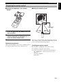
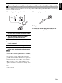
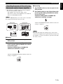
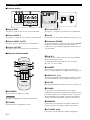
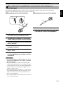
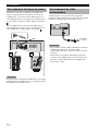
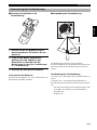
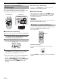
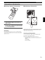
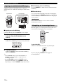
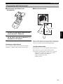
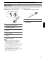
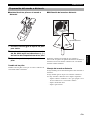
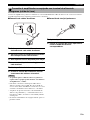
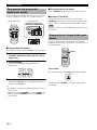
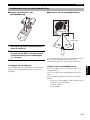
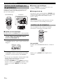
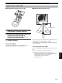
■ Installing the batteries in the remote
control
1 Press the mark on the battery cover and
open the cover.
2 Insert the two supplied type AA, R6, UM-3
batteries following the indications (+/–)
inside the battery compartment.
3 Close the battery cover.
Replacing the batteries
Change all of the batteries if you notice conditions such as
the operation range of the remote control decreases.
■ Using the remote control
The remote control transmits a directional infrared ray. Be
sure to aim the remote control directly at the remote control
sensor on the main unit during operation.
Handling the remote control
Be careful not to spill liquid on the remote control.
Be careful not to drop the remote control.
Do not leave the remote control in the following places:
– hot or humid places, such as near a heater or in a
bathroom
– extremely cold places
– dusty places
Preparing the remote control
3
1
2
Remote control
sensor
Approximately
6 m (20 ft)

5 En
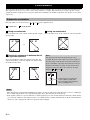
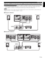
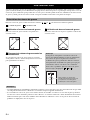
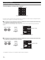
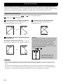
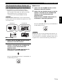
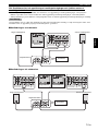
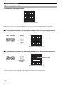
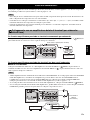
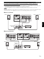
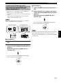
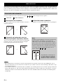
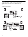
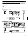
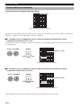
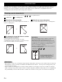
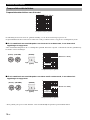
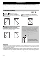
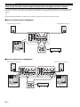
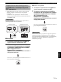
Since the low-end frequencies of audio signals feature long wavelengths, they are almost non-directional to human ears.
The super-bass range does not create a stereo image. Therefore, a single subwoofer may be enough to produce a high-
quality super-bass sound. However, using two subwoofers (similarly to L and R front speakers) can enhance your acoustic
experience.
Place the subwoofer as shown in fig. , or for the optimum effect.
: subwoofer : front speaker
Using one subwoofer
Place the subwoofer on the outside of either the left or right
front speaker.
Placing the subwoofer in between the left
and right front speakers
If you are placing the subwoofer in between the left and
right front speakers, position it slightly at an angle toward
the wall for better effect.
Using two subwoofers
Place the subwoofers on the outside of each front speaker.
• This unit features a magnetically shielded design. However, there is still a chance that placing it too close to a CRT-type
TV set might impair picture color. Should this happen, move this unit away from the TV set.
• If the speaker volume is very loud, furniture or window glass may resonate and the subwoofer itself may vibrate. In this
case, lower the volume level. To limit resonance, use a thick curtain or similar cloth that tends to absorb sound vibrations
effectively. Also, changing the subwoofer position may be helpful.
PLACEMENT
Subwoofer orientation
A
B
C
A
or
B
or
C
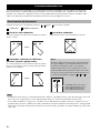
Note
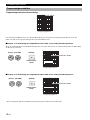
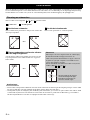
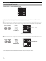
The placement shown in the figure below is also
possible. However, if the subwoofer system is placed
directly facing a wall, the bass effect may suffer due to
phase cancellation caused by the interference between
the direct and reflected sounds. To prevent this from
happening, place the subwoofer system at an angle.
(Figures , , and ).
A
B
C
There may be a case that you
cannot obtain enough super-
bass sound from the subwoofer
due to standing waves.
Notes

6 En
English
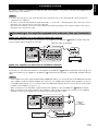
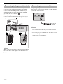
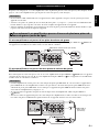
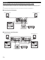
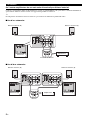
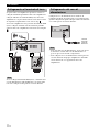
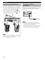
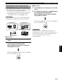
See pages 6 - 7 when your amplifier has subwoofer (line out) terminal(s), or see pages 8 - 10 when your amplifier has no
subwoofer (line out) terminal.
• Do not connect the power cord of this unit and other components into an AC outlet until all connections between
components are completed.
• Be sure to connect the left channel (L), right channel (R), “+” (red) and “–” (black) properly. Also, refer to the owner’s
manual of your component to be connected to this unit.
• The connection methods or the names of the terminals may differ depending on the component. Refer to the owner’s
manual of your component as well.
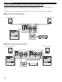
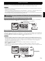
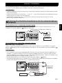
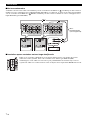
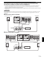
When your amplifier has a one-channel subwoofer terminal
Connect the subwoofer (or low pass etc.) terminal of your amplifier to the INPUT 3 ( /MONO) terminal of this unit
using a commercially available mono pin cable.
When your amplifier has two-channel subwoofer terminals
■ Using one subwoofer
Connect the “L” side subwoofer terminal of your amplifier to the INPUT 3 ( /MONO) terminal of this unit and “R” side
subwoofer terminal of your amplifier to the INPUT 3 ( ) terminal of this unit using a commercially available audio pin
cable.
• Some amplifiers have line output terminals labeled PRE OUT. When you connect this unit to the PRE OUT terminals
of the amplifier, make sure that the amplifier has at least two sets of PRE OUT terminals. If the amplifier has only one
set of PRE OUT terminals, do not connect this unit to the PRE OUT terminals. Instead, connect this unit to the speaker
terminals of the amplifier (see pages 8 - 9).
• When connecting to a monaural line output terminal of the amplifier, connect the INPUT 3 ( /MONO) terminal.
• When connecting to line output terminals of the amplifier, other speakers should not be connected to the OUTPUT
terminals on the rear panel of this unit. If connected, they will not produce sound.
CONNECTIONS
Notes
Connecting to the amplifier equipped with subwoofer (line out) terminal(s)
1
L
OUTPUT
TO SPEAKERS
FROM AMPLIFIER
L
L
L
R
R
R
LR
MONO
INPUT
3
INPUT
2
INPUT 1
OUTPUT
TO SPEAKERS
FROM AMPLIFIER
INPUT
3
INPUT
2
INPUT 1
L
L
L
R
R
R
LR
MONO
POWER
ON
OFF
Amplifier
Mono pin cable (not included)
Subwoofer
L
R
Notes
L
OUTPUT
TO SPEAKERS
FROM AMPLIFIER
L
L
L
R
R
R
LR
MONO
INPUT
3
INPUT
2
INPUT 1
OUTPUT
TO SPEAKERS
FROM AMPLIFIER
INPUT
3
INPUT
2
INPUT 1
L
L
L
R
R
R
LR
MONO
POWER
ON
OFF
Audio pin
cable
(not included)
Amplifier
Subwoofer

7 En
CONNECTIONS
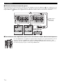
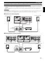
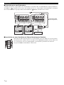
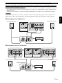
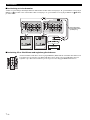
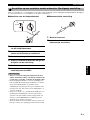
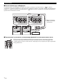
■Using two subwoofers
Connect the “R” side subwoofer terminal of your amplifier to the INPUT 3 ( ) terminal on this unit using a commercially
available mono pin cable, and connect the “L” side subwoofer terminal of your amplifier to the INPUT 3 ( /MONO)
terminal of this unit using a commercially available mono pin cable.
■Connecting to an amplifier equipped with a high cut function
If your amplifier can cut off high frequencies from signals sent to the subwoofer, connect the
amplifier to the subwoofer’s INPUT2 (LFE) terminal(s). This will promote higher sound quality
because the signal routing in the subwoofer is shortened by passing the built-in HIGH CUT circuit.
R
L
POWER
ON
OFF
OUTPUT
TO SPEAKERS
FROM AMPLIFIER
INPUT
3
INPUT
2
INPUT 1
L
L
L
R
R
R
LR
MONO
OUTPUT
TO SPEAKERS
FROM AMPLIFIER
INPUT
3
INPUT
2
INPUT 1
L
L
L
R
R
R
LR
MONO
OUTPUT
TO SPEAKERS
FROM AMPLIFIER
L
L
L
R
R
R
LR
MONO
OUTPUT
TO SPEAKERS
FROM AMPLIFIER
L
L
L
R
R
R
LR
MONO
INPUT
3
INPUT
2
INPUT 1
INPUT
3
INPUT
2
INPUT 1
POWER
ON
OFF
Mono pin cable
(not included)
Amplifier
Subwoofer
Subwoofer
L
L
R
R
R
R
MONO
INPUT
3
INPUT
2

8 En
CONNECTIONS
English
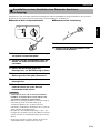
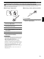
Connect an amplifier (and front speakers) to this unit using commercially available speaker cables. Refer to the following
instructions to make connections.
■ Connecting to the speaker cable
1 Remove approximately 15 mm (5/8”) of
insulation from each of the speaker cables.
2 Twist the exposed wires of the cable
together to prevent short circuits.
3 Turn the knob counterclockwise to loosen.
4 Insert the bare wire into the hole in the side
of each terminal.
5 Turn the knob clockwise to tighten.
6 Test the firmness of the connection by
pulling gently on the cable at the terminal.
• Do not let the bare speaker wires touch each other,
because this could damage this unit or the amplifier,
or both of them.
• For connection, keep the speaker cables as short as
possible. Do not bundle or roll up the excess part of the
cables. If the connections are faulty, no sound will be
heard from this unit or the speakers, or both of them.
• Make sure that the + and – polarity markings of the
speaker terminals are observed and set correctly. If these
cables are reversed, the sound will be unnatural and lack
bass.
• Do not insert the insulation into the hole. The sound may
not be produced.
■ Banana plug connection
1 Tighten the knob.
2 Insert the banana plug connecter into the
end of the corresponding terminal.
Connecting to an amplifier not equipped with a subwoofer (line out) terminal
2
Notes
12
5
3
4
15 mm
(5/8”)
1
2

9 En
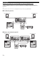
CONNECTIONS
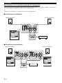
When your amplifier has one set of front speaker terminals
Connect the speaker terminals of the amplifier to the INPUT 1 terminals of this unit, and connect the OUTPUT terminals
of this unit to the front speakers using a commercially available speaker cable.
y
Connecting front speakers via this unit does not affect the sound quality.
■Using one subwoofer
■Using two subwoofers
OUTPUT
TO SPEAKERS
FROM AMPLIFIER
L
L
L
R
R
R
LR
MONO
INPUT
3
INPUT
2
INPUT 1
OUTPUT
TO SPEAKERS
FROM AMPLIFIER
INPUT
3
INPUT
2
INPUT 1
L
L
L
R
R
R
LR
MONO
POWER
ON
OFF
Front speaker (R) Front speaker (L)
Speaker terminals
Amplifier
Subwoofer
OUTPUT
TO SPEAKERS
FROM AMPLIFIER
INPUT
3
INPUT
2
INPUT 1
L
L
L
R
R
R
LR
MONO
OUTPUT
TO SPEAKERS
FROM AMPLIFIER
INPUT
3
INPUT
2
INPUT 1
L
L
L
R
R
R
LR
MONO
OUTPUT
TO SPEAKERS
FROM
AMPLIFIER
INPUT 3
INPUT 2
L
L
L
R
R
R
LR
MONO
OUTPUT
TO SPEAKERS
FROM AMPLIFIER
L
L
L
R
R
R
LR
MONO
OUTPUT
TO SPEAKERS
FROM AMPLIFIER
L
L
L
R
R
R
LR
MONO
INPUT
3
INPUT
2
INPUT 1
INPUT
3
INPUT
2
INPUT 1
POWER
ON
OFF
POWER
ON
OFF
Front speaker (R) Front speaker (L)
Speaker terminals
Subwoofer (R)
Amplifier
Subwoofer (L)

10 En
CONNECTIONS
English
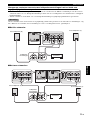
When your amplifier has two sets of front speaker terminals and both terminals can output
sound signals simultaneously
• Connect one set of front speaker terminals of the amplifier to the INPUT 1 terminals of this unit, and connect another
set of front speaker terminals of the amplifier to the front speakers using commercially available speaker cables.
• Set the amplifier so that both sets of front speaker terminals output sound signals simultaneously.
When your amplifier cannot output sound signals simultaneously even if you connect in this way, follow “When your
amplifier has one set of front speaker terminals” on page 9.
■ Using one subwoofer
■ Using two subwoofers
Note
OUTPUT
TO SPEAKERS
FROM AMPLIFIER
L
L
L
R
R
R
LR
MONO
INPUT
3
INPUT
2
INPUT 1
OUTPUT
TO SPEAKERS
FROM AMPLIFIER
INPUT
3
INPUT
2
INPUT 1
L
L
L
R
R
R
LR
MONO
POWER
ON
OFF
Front speaker (R)
Front speaker (L)
Speaker
terminals
Amplifier
Subwoofer
OUTPUT
TO SPEAKERS
FROM AMPLIFIER
L
L
L
R
R
R
LR
MONO
OUTPUT
TO SPEAKERS
FROM AMPLIFIER
L
L
L
R
R
R
LR
MONO
INPUT
3
INPUT
2
INPUT 1
INPUT
3
INPUT
2
INPUT 1
OUTPUT
TO SPEAKERS
FROM AMPLIFIER
INPUT
3
INPUT
2
INPUT 1
L
L
L
R
R
R
LR
MONO
OUTPUT
TO SPEAKERS
FROM AMPLIFIER
INPUT
3
INPUT
2
INPUT 1
L
L
L
R
R
R
LR
MONO
POWER
ON
OFF
POWER
ON
OFF
Front speaker (R)
Speaker
terminals
Front speaker (L)
Subwoofer (R) Subwoofer (L)
Amplifier

11 En
CONNECTIONS
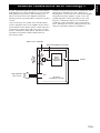
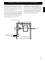
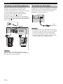
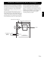
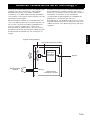
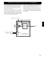
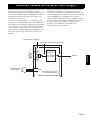
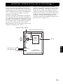
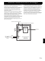
If this unit or the amplifier makes a hamming noise when
connecting to the speaker terminals of your amplifier,
connect both of the GND (ground) terminals on your
amplifier and this unit using commercially available
grounding wire as shown in fig. .
When your amplifier has no GND (ground) terminal,
connect to the screw that fastens the top cover of your
amplifier as shown in fig. .
When connecting the GND (ground) terminal, make sure
the power cables of the amplifier and this unit are not
plugged into the AC outlet.
Plug the supplied power cable into the AC IN of this unit
after all other connections are complete, and then plug the
power cable to an AC outlet.
• Do not use other power cables. Use the provided cable.
Use of other power cables may result in fire hazard or
electrical shock.
• Do not plug the power cable into the AC outlet of your
amplifier. Doing so may create distorted sounds or turn
off the power of your amplifier.
Connecting to the ground terminal
Note
A
B
OUTPUT
TO SPEAKERS
FROM AMPLIFIER
INPUT 1
L
L
L
R
R
R
LR
MONO
INPUT
3
INPUT
2
A B
Connecting the power cable
Notes
POWER
ON
OFF
To the AC
outlet

12 En
English
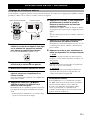
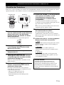
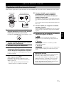
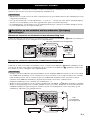
Before using this unit, adjust the volume balance of this unit to obtain the optimum volume and tone balance between the
front speakers and this unit by following the procedures below.
1 Set POWER switch on the rear panel of this
unit to the ON position, and then press
POWER to turn on this unit.
The STANDBY/ON indicator lights up green.
2 Press VOLUME to set the volume level of
this unit to the minimum (0).
3 Turn on the power of all other components.
4 Play back a source containing low-
frequency components and adjust the
volume level of your amplifier to the desired
listening level.
Set the tone control on your amplifier to the center
position.
5 Press HIGH CUT / to adjust to the
position where the desired response can be
obtained.
Normally, set the position to a level slightly higher
than the minimum frequency of the front speaker.
* To find out the minimum frequency of the front
speaker, refer to the owner’s manual of the front
speaker.
6 Press VOLUME to increase the volume
gradually to adjust the volume balance
between the front speaker and this unit.
Normally, set the volume to a level where you can
obtain a little more bass effect than when this unit is not
used.
y
If you cannot obtain the desired response, repeat steps
5 and 6.
7 Press PHASE to select the regular or
reverse mode.
Normally, set it to the reverse mode. If you cannot
obtain the desired response, set it to the regular mode.
8 Press B.A.S.S. to select a mode that is
suitable for the source.
1: WIDE
When a movie source is played, the low- frequency
effects are enhanced so that you can enjoy more
powerful sound.
2: NORMAL
When a music or movie etc. source is played, you can
enjoy natural bass sounds.
3: NARROW
When an ordinary music source is played, the
excessive low-frequency signals are cut off to make the
sound clearer.
USING THIS UNIT
Adjusting the sound balance
POWER
ON
OFF
POWER
STANDBY
SLEEP
PHASE
MEMORY
PRESET
HIGH CUT
VOLUME
213
B.A.S.S.
1
2,6
1
POWER
ON
OFF
Remote control Rear panel
SUBW
STANDBY
/ON
PHASE switch
In most situations, set this switch to select the reverse
mode. However, depending on your speaker systems
or listening condition, there may be a case when bet-
ter sound quality is obtained by selecting the regular
mode. Select the better mode by monitoring the
sound.

13 En
USING THIS UNIT
You can store up to 3 sets of your favorite settings (volume,
high-cut, phase and B.A.S.S. setting) in this unit.
■Storing the setting
In the following procedure, PRESET 1 is used as an
example.
1 Adjust the sound balance between the
volume, high cut, phase and
B.A.S.S. (see
page 12).
2 Press MEMORY.
The PRESET indicators on the front panel flash.
3 Press PRESET 1.
The PRESET 1 indicator lights up. The current setting
is stored as PRESET 1.
y
• In step 3, pressing a stored number overwrites the old
setting.
• While the VOLUME control or the H-CUT control is
rotating by pressing a PRESET, pressing another
PRESET is ineffective.
■ Recalling a setting
Press PRESET you want to recall (1, 2 or 3).
■ Memory back-up
Even if you turn off this unit by using the POWER switch
on the rear panel, this unit recalls the last setting when the
power is turned back on (Last memory function).
If the power is cut for more than one week, the setting is
cleared.
If you set the sleep timer, this unit automatically turns to
the standby mode after 120 minutes.
Press SLEEP.
The color of the STANDBY/ON indicator changes to
orange.
Pressing SLEEP again cancels the sleep timer.
Storing the sound balance settings
POWER
STANDBY
SLEEP
PHASE
MEMORY
PRESET
HIGH CUT
VOLUME
213
B.A.S.S.
H-CUT
SUBWOOFER SYSTEM NS-SW901
STANDBY
/ON
STANDBY
/ON
PHASE
123123
B.A.S.S.
PRESET
100Hz
40Hz
VOLUME
10
0
1
1
1
2
1
1
3
Remote control
Front panel
STANDBY/ON indicator
-SW901
3 123
PRESET
Note
Setting the sleep timer
POWER
STANDBY
SLEEP
PHASE
MEMORY
PRESET
HIGH CUT
VOLUME
213
B.A.S.S.
SLEEP
SUBW
STANDBY
/ON

14 En
USING THIS UNIT
English
* This function is available only for Yamaha amplifiers
that meet the following conditions:
– The amplifier was released in 2005 or later.
– The remote control of the amplifier has two different
buttons for STANDBY and ON.
When the AMP ID library code of the remote control has
been changed, this function may not work.
■ Setting
1 Set POWER switch on the rear panel to the
OFF position.
2 Set POWER switch to the ON position while
pressing and holding
STANDBY/ON switch
on the front panel.
Continue holding down
STANDBY/ON
switch for 3 seconds or longer.
After the STANDBY/ON indicator flashes 4 times, the
setting is completed.
■ Canceling
1 Set POWER switch on the rear panel to the
OFF position.
2 Set POWER switch to the ON position while
pressing and holding
STANDBY/ON switch
on the front panel.
Continue holding down
STANDBY/ON
switch for 3 seconds or longer.
After the STANDBY/ON indicator flashes 2 times, the
setting is completed.
Place this unit within the operating range of the remote
control of the amplifier. If you place this unit far away from
the amplifier, you may not be able to operate this unit with
the remote control.
Operating the power of this unit using
the remote control of your amplifier
Note
H-CUT
SUBWOOFER SYSTEM NS-SW901
STANDBY
/ON
STANDBY
/ON
PHASE
123123
B.A.S.S.
PRESET
100Hz
40Hz
VOLUME
10
0
POWER
ON
OFF
POWER
ON
OFF
POWER switch
STANDBY/ON switch
Rear panel
Front panel
SUBW
STANDBY
/ON
Note
SUBW
STANDBY
/ON

15 En
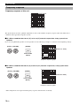
USING THIS UNIT
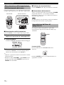
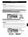
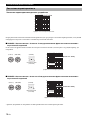
Frequency response of this unit
The figures below show the optimum adjustment of each control and the frequency response when this subwoofer is
combined with a typical front speaker system.
■EX.1 When combined with 10 cm (
4"
) or 13 cm (5") acoustic suspension, 2-way system front
speakers
If you are using NS-F901 speakers as front speakers, use the following example as a reference when adjusting settings.
■EX.2 When combined with 20 cm (8") or 25 cm (10") acoustic suspension, 2-way system front
speakers
* These diagrams do not depict actual frequency response characteristics accurately.
Frequency response
reverse mode
(Green)
reverse mode
(Green)
20 50 100 200 500Hz
40
50
60
70
80
90
dB
H-CUT 140 Hz
Frequency response graph*
H-CUT
140Hz
40Hz
VOLUME
10
0
(H-CUT) (VOLUME)
OOFER SYSTEM S
PHASE
1
(PHASE)
20 50 100 200 500Hz
40
50
60
70
80
90
dB
NS-SW901 (H-CUT 60 - 70 Hz)
Front
speaker
Frequency response graph*
H-CUT
140Hz
40Hz
VOLUME
10
0
(H-CUT) (VOLUME)
OOFER SYSTEM S
PHASE
1
(PHASE)
20 50 100 200 500Hz
40
50
60
70
80
90
dB
NS-SW901 (H-CUT 50 - 60Hz)
Front
speaker
Frequency response graph*

16 En
English
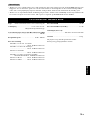
In 1988, Yamaha brought to the speaker systems utilizing
YST (Yamaha Active Servo Technology) to give powerful,
high quality bass reproduction. This technology uses a
direct connection between the amplifier and speaker,
allowing accurate signal transmission and precise speaker
control.
As this technology uses speaker units controlled by the
negative impedance drive of the amplifier and resonance
generated between the cabinet capacity volume and port, it
creates more resonant energy (the “air woofer” concept)
than the standard bass reflex method. This allows for bass
reproduction from much smaller cabinets than was
previously possible.
Yamaha’s newly developed Advanced YST II adds many
refinements to Yamaha Active Servo Technology,
allowing better control of the forces driving the amplifier
and speaker. From the amplifier’s point of view, the
speaker impedance changes depending on the sound
frequency. Yamaha developed a new circuit design
combining negative-impedance and constant-current
drives, which provides a more stable performance and
clear bass reproduction without any murkiness.
Advanced Yamaha Active Servo Technology II
High-amplitude
bass sound
Port
Cabinet
Advanced impedance Converter
Active
Servo
Processing
Amplifier
Signals of low amplitude
Air woofer
(Helmholtz resonator)
Signals

17 En
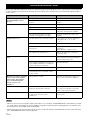
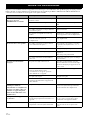
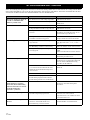
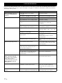
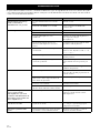
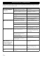
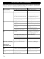
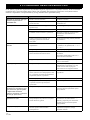
Refer to the chart below when this unit does not function properly. If the problem you are experiencing is not listed below
or if the instructions given below do not help, disconnect the power cord and contact your authorized Yamaha dealer or
service center.
• When an excessive level of signal is input to this unit for 5 to 15 minutes, the POWER indicator starts flashing to alarm
you of the danger of damaging the power amplifier and speaker of this unit. If the signal input lasts for 5 minutes more,
this unit turns into the standby mode automatically.
• When an enormous amount of signal is input, the power of this unit is turned off immediately. To turn on this unit again,
press STANDBY/ON switch on the front panel.
TROUBLESHOOTING
Problem Cause Remedy
Power is not supplied even though
the STANDBY/ON switch is
pressed.
The power plug is not securely connected. Connect it securely.
The POWER switch is set to the OFF
position.
Set the POWER switch to the ON
position.
No sound. The volume is set to the minimum (0). Raise the volume.
Speaker cables are not connected securely. Connect them securely.
The signals from the amplifier are too low. Increase the volume of the amplifier or the
component connected to the amplifier.
The signal from the subwoofer output
terminal of the amplifier is not output.
Check the speaker mode setting on the
amplifier.
Sound level is too low. Speaker cables are not connected correctly. Connect them correctly, that is L (left) to
L, R (right) to R, “+” to “+” and
“–” to “–”.
Setting of the phase is not proper. Set the phase to the other position.
A source sound with few bass frequencies is
being played.
Play a source sound with bass
frequencies.
Set the H-CUT to a higher position.
It is influenced by standing waves. Relocate the subwoofer or change its
positioning angle.
The remote control does not
work.
Wrong distance or angle. Use the remote control within a maximum
range of 6 m and no more then 30 degrees
off-axis from the front panel.
Direct sunlight or lighting from an inverter
type of fluorescent lamp etc. is striking the
remote control sensor of this unit.
Reposition this unit.
The batteries are weak. Replace all batteries.
There are obstacles between the remote
control signal receiver on the unit and the
remote control.
Remove the obstacles.
This unit is not turned on with the
remote control of the amplifier.
(when setting “Operating the
power of this unit using the
remote control of your
amplifier”)
Wrong distance or angle. Place this unit within the operating range
of the remote control of the amplifier.
The household breaker goes off. This unit consumes much electricity when a
high level signal is input to this unit.
Turn down the volume on the amplifier
etc. connected to this unit or cut off the
power of other unused equipment.
An object has fallen into the port. Do not try to remove the object. Attempting
to remove the object may cause a
malfunction.
Contact an authorized Yamaha dealer or
service center.
Notes
Sayfa yükleniyor...
Sayfa yükleniyor...
Sayfa yükleniyor...
Sayfa yükleniyor...
Sayfa yükleniyor...
Sayfa yükleniyor...
Sayfa yükleniyor...
Sayfa yükleniyor...
Sayfa yükleniyor...
Sayfa yükleniyor...
Sayfa yükleniyor...
Sayfa yükleniyor...
Sayfa yükleniyor...
Sayfa yükleniyor...
Sayfa yükleniyor...
Sayfa yükleniyor...
Sayfa yükleniyor...
Sayfa yükleniyor...
Sayfa yükleniyor...
Sayfa yükleniyor...
Sayfa yükleniyor...
Sayfa yükleniyor...
Sayfa yükleniyor...
Sayfa yükleniyor...
Sayfa yükleniyor...
Sayfa yükleniyor...
Sayfa yükleniyor...
Sayfa yükleniyor...
Sayfa yükleniyor...
Sayfa yükleniyor...
Sayfa yükleniyor...
Sayfa yükleniyor...
Sayfa yükleniyor...
Sayfa yükleniyor...
Sayfa yükleniyor...
Sayfa yükleniyor...
Sayfa yükleniyor...
Sayfa yükleniyor...
Sayfa yükleniyor...
Sayfa yükleniyor...
Sayfa yükleniyor...
Sayfa yükleniyor...
Sayfa yükleniyor...
Sayfa yükleniyor...
Sayfa yükleniyor...
Sayfa yükleniyor...
Sayfa yükleniyor...
Sayfa yükleniyor...
Sayfa yükleniyor...
Sayfa yükleniyor...
Sayfa yükleniyor...
Sayfa yükleniyor...
Sayfa yükleniyor...
Sayfa yükleniyor...
Sayfa yükleniyor...
Sayfa yükleniyor...
Sayfa yükleniyor...
Sayfa yükleniyor...
Sayfa yükleniyor...
Sayfa yükleniyor...
Sayfa yükleniyor...
Sayfa yükleniyor...
Sayfa yükleniyor...
Sayfa yükleniyor...
Sayfa yükleniyor...
Sayfa yükleniyor...
Sayfa yükleniyor...
Sayfa yükleniyor...
Sayfa yükleniyor...
Sayfa yükleniyor...
Sayfa yükleniyor...
Sayfa yükleniyor...
Sayfa yükleniyor...
Sayfa yükleniyor...
Sayfa yükleniyor...
Sayfa yükleniyor...
Sayfa yükleniyor...
Sayfa yükleniyor...
Sayfa yükleniyor...
Sayfa yükleniyor...
Sayfa yükleniyor...
Sayfa yükleniyor...
Sayfa yükleniyor...
Sayfa yükleniyor...
Sayfa yükleniyor...
Sayfa yükleniyor...
Sayfa yükleniyor...
Sayfa yükleniyor...
Sayfa yükleniyor...
Sayfa yükleniyor...
Sayfa yükleniyor...
Sayfa yükleniyor...
Sayfa yükleniyor...
Sayfa yükleniyor...
Sayfa yükleniyor...
Sayfa yükleniyor...
Sayfa yükleniyor...
Sayfa yükleniyor...
Sayfa yükleniyor...
Sayfa yükleniyor...
Sayfa yükleniyor...
Sayfa yükleniyor...
Sayfa yükleniyor...
Sayfa yükleniyor...
Sayfa yükleniyor...
Sayfa yükleniyor...
Sayfa yükleniyor...
Sayfa yükleniyor...
Sayfa yükleniyor...
Sayfa yükleniyor...
Sayfa yükleniyor...
Sayfa yükleniyor...
Sayfa yükleniyor...
Sayfa yükleniyor...
Sayfa yükleniyor...
Sayfa yükleniyor...
Sayfa yükleniyor...
Sayfa yükleniyor...
Sayfa yükleniyor...
Sayfa yükleniyor...
Sayfa yükleniyor...
Sayfa yükleniyor...
Sayfa yükleniyor...
Sayfa yükleniyor...
Sayfa yükleniyor...
Sayfa yükleniyor...
Sayfa yükleniyor...
Sayfa yükleniyor...
Sayfa yükleniyor...
Sayfa yükleniyor...
Sayfa yükleniyor...
Sayfa yükleniyor...
Sayfa yükleniyor...
Sayfa yükleniyor...
Sayfa yükleniyor...
Sayfa yükleniyor...
Sayfa yükleniyor...
Sayfa yükleniyor...
Sayfa yükleniyor...
Sayfa yükleniyor...
Sayfa yükleniyor...
Sayfa yükleniyor...
Sayfa yükleniyor...
Sayfa yükleniyor...
-
 1
1
-
 2
2
-
 3
3
-
 4
4
-
 5
5
-
 6
6
-
 7
7
-
 8
8
-
 9
9
-
 10
10
-
 11
11
-
 12
12
-
 13
13
-
 14
14
-
 15
15
-
 16
16
-
 17
17
-
 18
18
-
 19
19
-
 20
20
-
 21
21
-
 22
22
-
 23
23
-
 24
24
-
 25
25
-
 26
26
-
 27
27
-
 28
28
-
 29
29
-
 30
30
-
 31
31
-
 32
32
-
 33
33
-
 34
34
-
 35
35
-
 36
36
-
 37
37
-
 38
38
-
 39
39
-
 40
40
-
 41
41
-
 42
42
-
 43
43
-
 44
44
-
 45
45
-
 46
46
-
 47
47
-
 48
48
-
 49
49
-
 50
50
-
 51
51
-
 52
52
-
 53
53
-
 54
54
-
 55
55
-
 56
56
-
 57
57
-
 58
58
-
 59
59
-
 60
60
-
 61
61
-
 62
62
-
 63
63
-
 64
64
-
 65
65
-
 66
66
-
 67
67
-
 68
68
-
 69
69
-
 70
70
-
 71
71
-
 72
72
-
 73
73
-
 74
74
-
 75
75
-
 76
76
-
 77
77
-
 78
78
-
 79
79
-
 80
80
-
 81
81
-
 82
82
-
 83
83
-
 84
84
-
 85
85
-
 86
86
-
 87
87
-
 88
88
-
 89
89
-
 90
90
-
 91
91
-
 92
92
-
 93
93
-
 94
94
-
 95
95
-
 96
96
-
 97
97
-
 98
98
-
 99
99
-
 100
100
-
 101
101
-
 102
102
-
 103
103
-
 104
104
-
 105
105
-
 106
106
-
 107
107
-
 108
108
-
 109
109
-
 110
110
-
 111
111
-
 112
112
-
 113
113
-
 114
114
-
 115
115
-
 116
116
-
 117
117
-
 118
118
-
 119
119
-
 120
120
-
 121
121
-
 122
122
-
 123
123
-
 124
124
-
 125
125
-
 126
126
-
 127
127
-
 128
128
-
 129
129
-
 130
130
-
 131
131
-
 132
132
-
 133
133
-
 134
134
-
 135
135
-
 136
136
-
 137
137
-
 138
138
-
 139
139
-
 140
140
-
 141
141
-
 142
142
-
 143
143
-
 144
144
-
 145
145
-
 146
146
-
 147
147
-
 148
148
-
 149
149
-
 150
150
-
 151
151
-
 152
152
-
 153
153
-
 154
154
-
 155
155
-
 156
156
-
 157
157
-
 158
158
-
 159
159
-
 160
160
-
 161
161
-
 162
162
-
 163
163
-
 164
164


diğer dillerde
- español: Yamaha NS-SW901 El manual del propietario
- français: Yamaha NS-SW901 Le manuel du propriétaire
- italiano: Yamaha NS-SW901 Manuale del proprietario
- svenska: Yamaha NS-SW901 Bruksanvisning
- Deutsch: Yamaha NS-SW901 Bedienungsanleitung
- English: Yamaha NS-SW901 Owner's manual
- dansk: Yamaha NS-SW901 Brugervejledning
- русский: Yamaha NS-SW901 Инструкция по применению
- suomi: Yamaha NS-SW901 Omistajan opas
- Nederlands: Yamaha NS-SW901 de handleiding