Samsung SCC-B2003P Kullanım kılavuzu
- Kategori
- Tamamlayıcı müzik ekipmanı
- Tip
- Kullanım kılavuzu
Bu kılavuz aynı zamanda aşağıdakiler için de uygundur:

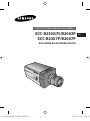
DAY/NIGHT COLOR CAMERA
SCC-B2303(P)/B2003P
SCC-B2307P/B2007P
User’s Manual
E
Tu
B2303(P)/2003P/B2307P/2007P 2007.5.15 5:7 PM Page 1

E
2
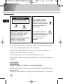
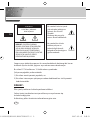
CAUTION: TO REDUCE THE
RISK OF ELECTRIC SHOCK,
DO NOT REMOVE REAR
COVER. NO USER
SERVICEABLE PARTS INSIDE.
REFER TO QUALIFIED
SERVICE PERSONNEL.
To prevent damage which may result in fire or electric shock hazard,
do not expose this appliance to rain or moisture.
This device complies with part 15 of the FCC Rules. Operation is
subject to the following two conditions.
1) This device may not cause harmful interference, and
2) This device must accept any interference that may cause undesired
operation.
CAUTION:
Danger of explosion if battery is incorrectly replaced.
Replace only with the same or equivalent type recommended by the
manufacturer.
Dispose of used batteries according to the manufacturer’s instructions.
This symbol indicates
high voltage is present
inside. It is dangerous to
make any kind of contact
with any inside part of
this product.
This symbol alerts you
that important literature
concerning operation and
maintenance has been
included with this
product.
CAUTION
RISK OF ELECTRIC
SHOCK DO NOT OPEN
B2303(P)/2003P/B2307P/2007P 2007.5.15 5:7 PM Page 2

3
Important Safety Instructions
E
1. Read these instructions.
2. Keep these instructions.
3. Heed all warnings.
4. Follow all instructions.
5. Do not use this apparatus near water.
6. Clean only with dry cloth.
7. Do not block any ventilation openings. Install in accordance
with the manufacturer’s instructions.
8. Do not install near any heat sources such as radiators, heat
registers, or other apparatus (including amplifiers) that produce
heat.
9. Do not defeat the safety purpose of the polarized or grounding-
type plug. A polarized plug has two blades with one wider than
the other. A grounding type plug has two blades and a third
grounding prong. The wide blade or the third prong are
provided for your safety. If the provided plug does not fit into
your outlet, consult an electrician for replacement of the
obsolete outlet.
10. Protect the power cord from being from being walked on or
pinched particularly at plugs, convenience receptacles, and the
point where they exit from the apparatus.
11. Only use attachments/accessories specified by the
manufacturer.
12. Use only with cart, stand, tripod, bracket, or table specified by
the manufacturer, or sold with the apparatus. When a used,
caution when moving the cart/apparatus combination to avoid
injury from tip-over.
13. Unplug this apparatus. When a cart is used, use caution when
moving the cart/apparatus combination to avoid injury from tip-
over.
14. Refer all servicing to qualified service personnel. Servicing is
required when the apparatus has been damaged in any way,
such as power-supply cord or plug is damaged, liquid has been
spilled or objects have fallen into the apparatus, the apparatus
has been exposed to rain or moisture, does not operate
normally, or been dropped.
B2303(P)/2003P/B2307P/2007P 2007.5.15 5:7 PM Page 3

E
4
Contents
Chapter 1 Introduction ........................................................ 5
Chapter 2 Special Features ............................................. 6
Chapter 3 Part Names and Functions ............................... 7
Chapter 4 Installation .......................................................... 12
Cautions for Installation and Use ....................... 13
Connecting Automatic Shutter Lens Connector
........... 14
Fixing Lens and Adjusting Lens Selection Switch
....... 15
Adjusting Back Focus ........................................ 16
Connecting Cables ............................................ 18
Chapter 5 Camera Set-Up ................................................. 20
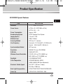
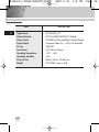
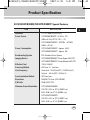
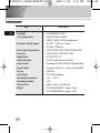
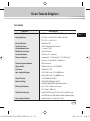
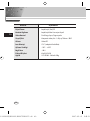
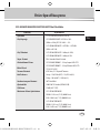
Appendix Product Specification ........................................ 39
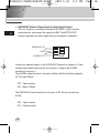
NOTE: Avoid aiming the camera directly towards extremely bright
objects such as the sun, as this may damage the CCD image sensor.
B2303(P)/2003P/B2307P/2007P 2007.5.15 5:7 PM Page 4

5
Chapter 1 Introduction
E
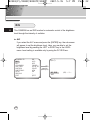
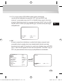
The DAY/NIGHT Camera operates in a color mode in an the
illumination over the standard value and otherwise in B/W mode by
deleting the IR Cut function, which contributes to the improvement
of sensitivity so that it is called a low illumination camera which is
able to identify objects in a dark area. Meanwhile, it has
incorporated a Sense Up function owing to a low speed shutter and
a field accumulation method to improve its low illumination feature
prominently.
The DAY/NIGHT Camera is mostly used in dark places like
basement parking lots with a comparatively low illumination. In
daytime, it provides a color screen of high density with a horizontal
resolution of 480, and, at night, it utilizes the DAY/NIGHT function
as well as the Sense Up function to identify objects. In same cases,
you may use this camera in relation to the infrared ray emission
equipment additionally.
[DAY/NIGHT]
It is a function of a color camera to delete the fiter with the
IR Cut function in an illumination below the standard value
so that it has a better sensitivity.
B2303(P)/2003P/B2307P/2007P 2007.5.15 5:7 PM Page 5

6
Chapter 2 Special Features
E
High Sensitivity
It has an up-to-date 1/3" Super(EXview)-HAD IT CCD for an image of high
sensitivity.
Low Illumination Function
It has both a low illumination function and DAY/NIGHT function based on
digital signal technology in order to operate in the worst environment
without light.
Digital Zoom Function
It has a digital zoom function for a 10 time enlargement as a maximum. (If
you turn the PIP function to the Digital Zoom mode, the whole screen will
be displayed as a PIP screen.
Superior Back Light Adjustment Function
In case the object has a bright illumination or sunlight behind it, this camera
adjusts the image shaded by the back light for clear photographs.
Digital Power Supply Synchronization Method
The Full Digital Method Line Lock is realized in this camera, which adjusts
the vertical camera synchronization directly to improve controllability and
reliability of the camera.
Resolution
It realizes high resolution resulting from full digital image processing
supported by a state-of-art digital signal technology.
Output Signal Setting
It is able to reverse video output signals and set both a vertical and
horizontal profile.
B2303(P)/2003P/B2307P/2007P 2007.5.15 5:7 PM Page 6

7
Chapter 3 Part Names and Functions
E
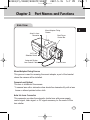
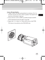
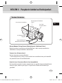
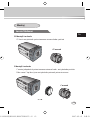
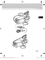
Side View
Mount Adapter Fixing Groove
This groove is used for screwing the mount adapter, a part of the bracket
where the camera will be installed.
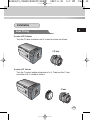
Camera Lens(Option)
This lens is installed in the camera.
* A camera lens with a stained surface should be cleaned softly with a lens
tissue or ethanol painted cotton cloth.
Auto Iris Lens Connector
This connector provides the automatic shutter lens with power supply,
control signal, video signal, or DC signal necessary for the control of the
lens shutter
Automatic Shutter
Lens Control Cable
ALC Lens
Selection Switch
Auto Iris Lens
Connector
Mount Adapter Fixing
Groove
Back Focus
Control Bar
Camera Lens
B2303(P)/2003P/B2307P/2007P 2007.5.15 5:7 PM Page 7

E
8
Auto Iris Lens Control Cable
This cable transmits the control signal from the camera to control the lens
shutter.
Back Focus Control Bar
It controls the back focus.
ALC Lens Setting Switch
This switch sets the Auto Iris lens type for use.
DC : When you attach an Auto Iris lens requiring the DC control signal,
please put this switch in the DC position.
VIDEO : When you attach an Auto Iris lens requiring the video control
signal, please put this switch in the VIDEO position.
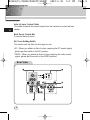
Rear View
B2303(P)/2003P/B2307P/2007P 2007.5.15 5:7 PM Page 8

E
9
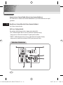
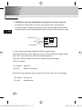
① Power Display LED
When the camera is supplied with power, LED is on.
➁ Video Output Terminal
The monitor video input terminal is connected with this terminal through
which the camera video signal comes out.
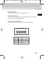
➂ Remote Input Terminal(RS-232)
This terminal is used for camera control at the production plant.
1
2 3 4
1 TXD
2 RXD
3 +5V
4 GND
B2303(P)/2003P/B2307P/2007P 2007.5.15 5:7 PM Page 9

E
10
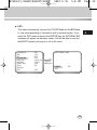
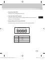
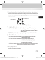
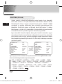
➃ DAY/NIGHT External Signal Input & Alarm Signal Output
This is a function to receive the external DAY/NIGHT signal from the
sensor(option) and convert the signal into BW. The MOTION DET
function generates an alarm signal when a movement is detected.
①
➁
DAY/NIGHT IN
GND
ALARM OUT
Connect an external sensor to the DAY/NIGHT terminal as shown in ① then
connect any external device such as a buzzer or lamp to the ALARM
terminal as shown in ➁.
The ALARM output terminal is an open collector with the following capacity:
DC 16V and 100mA.
OFF : Open contact
ON : Below 100mA
The DAY/NIGHT input terminal has the input of DC 5V pull-up and over
0.2mA.
OFF : Open contact
ON : Closed contact
B2303(P)/2003P/B2307P/2007P 2007.5.15 5:7 PM Page 10

E
11
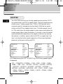
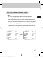
⑤ Camera Operation Switch(Setup Switch)
The function of the camera operation switch changes depending on
whether the camera is currently in the usual operation mode(No setup
menu is seen on the screen) or the setup menu mode.
In the usual operation mode
[LEFT/RIGHT] key : Press key for about 2 seconds and the
menu comes out to control the DC IRIS level. The
[LEFT] key raises the level and the [RIGHT] key
lowers the level.
[ENTER] key : It is used to enter the Setup menu.(Press it about 2
seconds.)
In the setup menu mode
[UP/DOWN] key : These keys move up or down the cursor.
[LEFT/RIGHT] key : These keys move the cursor to the left or right or
identify the values sequentially which can be
assigned in each setup menu.
[ENTER] key : It is used to enter a sub-menu of a setup menu by
clicking the setup menu or to set the current value.
➅ Power Connection Port
This port is connected to the power(adapter) cable.
[LEFT/RIGHT] key
[ENTER] key
[UP/DOWN] key
B2303(P)/2003P/B2307P/2007P 2007.5.15 5:7 PM Page 11

12
Chapter 4 Installation
E
This chapter describes what should be checked before installation, how to
set the installation environment, and what should be done during
installation. Then, it describes how to install the camera and connect the
cable in actual circumstances.
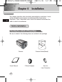
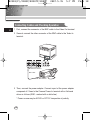
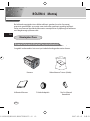
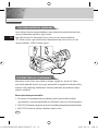
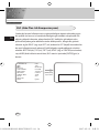
Be sure to check if the following items are included in the package.
Before Installation
Checking the contents of the package
Camera Camera Holder(Mount)
C Mount Adapter Auto Iris
Lens Connector
User's Manual
B2303(P)/2003P/B2307P/2007P 2007.5.15 5:7 PM Page 12

E
13
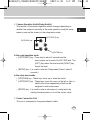
① Do not disassemble the camera on your own.
➁ Be careful when handling the camera at all times. Do not strike the
camera with your fists or shake it. The camera should be stored and
treated with care to avoid any damage.
➂ Do not put or operate the camera in rain or wet places.
➃ Do not scrub the camera body with rough sandpaper when it is stained.
Please use a dry cloth at all times.
⑤ Put the camera in a cool area free from direct light. Otherwise, the
camera may be damaged.
What should be done during installation and use
B2303(P)/2003P/B2307P/2007P 2007.5.15 5:7 PM Page 13

E
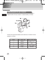
14
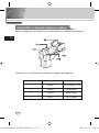
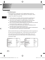
Connecting Auto Iris Lens Connector
Prepare the Auto Iris lens connector, a camera auxiliary, as follows :
Connect each uncovered shutter control cable wire to the Auto Iris lens
connector as follows.
Pin No. DC Control Type VIDEO Control Type
1 Damp(-) Power (+12V)
2 Damp(+) N/A
3Drive(+) VIDEO Signal
4 Drive(-) GROUND
B2303(P)/2003P/B2307P/2007P 2007.5.15 5:7 PM Page 14

E
15
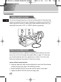
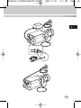
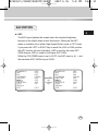
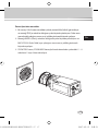
Installation
Lens Fixing
In case of CS lenses
Turn the CS lens clockwise until it is fixed as shown as follows.
In case of C lenses
Turn the C-mount adapter clockwise to fix it. Then turn the C lens
clockwise until it is fixed as follows.
CS lens
C lens
B2303(P)/2003P/B2307P/2007P 2007.5.15 5:7 PM Page 15

E
16
Setting Switch Control
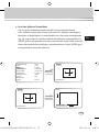
Back Focus Adjustment
You should change the position of the lens setting switch on the side of the
camera according to the lens type. Depending on whether you fixed the DC
control type Auto Iris lens or video control type automatic shutter lens, you
should put the switch in "DC" or "VIDEO" position respectively.
The camera back focus is adjusted at the plant before delivery, but some
lenses are out of focus though the number differs in types. If it's the case,
you should make the back focus adjustment as follows. First, this is the
back focus adjustment procedure for fixed focus lenses.
Lenses without zoom function
① Image an object with high resolution(letticed) at more than 10m distance
and put the lens focus ring in the infinite(
∞
) position.
➁ Rotate the BACK FOCUS control bar until the object is seen best.
➂ Tighten the BACK FOCUS control bar fixing screw.
B2303(P)/2003P/B2307P/2007P 2007.5.15 5:7 PM Page 16

E
17
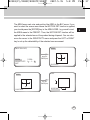
Lenses with zoom function
① Image an object with high resolution(letticed) at a distance of 3 to 5 m
and zoom in the lens as close to TELE as possible. Then adjust the lens
focus bar until the object is seen best.
➁ Zoom in the lens as close to WIDE as possible and adjust the BACK
FOCUS adjustment bar until the object is seen best.
➂ Repeat from ① to ➁ above 2 or 3 times until the focus on the ZOOM
TELE side is in line with that on the ZOOM WIDE side.
B2303(P)/2003P/B2307P/2007P 2007.5.15 5:7 PM Page 17

E
18
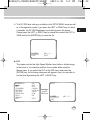
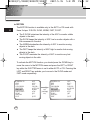
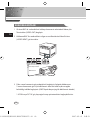
Connecting Cables and Checking Operation
1 First, connect the connector of the BNC cable to the Video Out terminal
2 Second, connect the other connector of the BNC cable to the Video In
terminal.
3 Then, connect the power adapter. Connect a part of the power adapter
composed of 2 lines to the Camera Power In terminal with a flat-head
driver as follows.(GND : marked with a white line)
* Power source may be AC24V or DC12V irrespective of polarity
BNC cable
Video Out Terminal
Video In Terminal of
Monitor Rear Surface
B2303(P)/2003P/B2307P/2007P 2007.5.15 5:7 PM Page 18

E
19
B2303(P)/2003P/B2307P/2007P 2007.5.15 5:7 PM Page 19

20
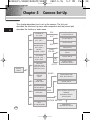
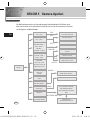
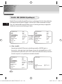
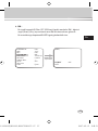
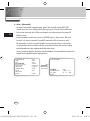
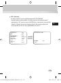
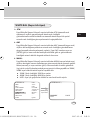
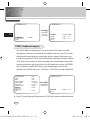
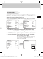
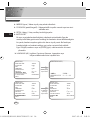
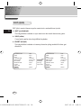
Chapter 5 Camera Set-Up
E
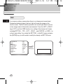
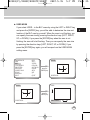
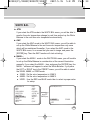
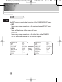
This chapter describes how to set up the camera. The first part
describes the whole set up menu and composition and the second part
describes the function of each menu.
ON...
ALC...
ELC...
BW...
EXT...
AUTO...
USER...
COLOR...
MANU...
LINE...
MOTION DET ON...
CAMERA ID
ON.../OFF
CAMERA ID AND
LOCATION SETUP
DC IRIS SETUP
LEVEL SETUP
AREA SETUP
GAIN, AGC COLOR
SETUP
BURST SETUP
BURST, LEVEL,
DURATION SETUP
3200K/5600K/USER
RED, BLUE SETUP
PHASE SETUP
AREA SETUP
SENSITIVITY SETUP
BAU DRATE D-ZOOM, PIP,
MIRROR,
POSI/NEGA,DETAIL,
MOTION DET
IRIS
ALC.../ELC...
COLOR/BW
COLOR.../BW.../
AUTO.../EXT...
SHUTTER
OFF/1/100~1/10K
OFF/AUTO X2~X128
OFF/FIX X2~X128
AGC
OFF/LOW
/HIGH
MOTION
S.SLOW~F.FAST
WHITE BAL
ATW/AWC/MANU...
SYNC
INT/LINE...
SETUP
MENU
SPECIAL
...
EXIT
QUIT/SAVE/PRESET
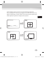
BLC
OFF/BOTTOM.../
TOP.../LEFT.../
RIGHT.../
CENTER.../USER..
B2303(P)/2003P/B2307P/2007P 2007.5.15 5:7 PM Page 20
Sayfa yükleniyor...
Sayfa yükleniyor...
Sayfa yükleniyor...
Sayfa yükleniyor...
Sayfa yükleniyor...
Sayfa yükleniyor...
Sayfa yükleniyor...
Sayfa yükleniyor...
Sayfa yükleniyor...
Sayfa yükleniyor...
Sayfa yükleniyor...
Sayfa yükleniyor...
Sayfa yükleniyor...
Sayfa yükleniyor...
Sayfa yükleniyor...
Sayfa yükleniyor...
Sayfa yükleniyor...
Sayfa yükleniyor...
Sayfa yükleniyor...
Sayfa yükleniyor...
Sayfa yükleniyor...
Sayfa yükleniyor...
Sayfa yükleniyor...
Sayfa yükleniyor...
Sayfa yükleniyor...
Sayfa yükleniyor...
Sayfa yükleniyor...
Sayfa yükleniyor...
Sayfa yükleniyor...
Sayfa yükleniyor...
Sayfa yükleniyor...
Sayfa yükleniyor...
Sayfa yükleniyor...
Sayfa yükleniyor...
Sayfa yükleniyor...
Sayfa yükleniyor...
Sayfa yükleniyor...
Sayfa yükleniyor...
Sayfa yükleniyor...
Sayfa yükleniyor...
Sayfa yükleniyor...
Sayfa yükleniyor...
Sayfa yükleniyor...
Sayfa yükleniyor...
Sayfa yükleniyor...
Sayfa yükleniyor...
Sayfa yükleniyor...
Sayfa yükleniyor...
Sayfa yükleniyor...
Sayfa yükleniyor...
Sayfa yükleniyor...
Sayfa yükleniyor...
Sayfa yükleniyor...
Sayfa yükleniyor...
Sayfa yükleniyor...
Sayfa yükleniyor...
Sayfa yükleniyor...
Sayfa yükleniyor...
Sayfa yükleniyor...
Sayfa yükleniyor...
Sayfa yükleniyor...
Sayfa yükleniyor...
Sayfa yükleniyor...
Sayfa yükleniyor...
Sayfa yükleniyor...
Sayfa yükleniyor...
-
 1
1
-
 2
2
-
 3
3
-
 4
4
-
 5
5
-
 6
6
-
 7
7
-
 8
8
-
 9
9
-
 10
10
-
 11
11
-
 12
12
-
 13
13
-
 14
14
-
 15
15
-
 16
16
-
 17
17
-
 18
18
-
 19
19
-
 20
20
-
 21
21
-
 22
22
-
 23
23
-
 24
24
-
 25
25
-
 26
26
-
 27
27
-
 28
28
-
 29
29
-
 30
30
-
 31
31
-
 32
32
-
 33
33
-
 34
34
-
 35
35
-
 36
36
-
 37
37
-
 38
38
-
 39
39
-
 40
40
-
 41
41
-
 42
42
-
 43
43
-
 44
44
-
 45
45
-
 46
46
-
 47
47
-
 48
48
-
 49
49
-
 50
50
-
 51
51
-
 52
52
-
 53
53
-
 54
54
-
 55
55
-
 56
56
-
 57
57
-
 58
58
-
 59
59
-
 60
60
-
 61
61
-
 62
62
-
 63
63
-
 64
64
-
 65
65
-
 66
66
-
 67
67
-
 68
68
-
 69
69
-
 70
70
-
 71
71
-
 72
72
-
 73
73
-
 74
74
-
 75
75
-
 76
76
-
 77
77
-
 78
78
-
 79
79
-
 80
80
-
 81
81
-
 82
82
-
 83
83
-
 84
84
-
 85
85
-
 86
86


Samsung SCC-B2003P Kullanım kılavuzu
- Kategori
- Tamamlayıcı müzik ekipmanı
- Tip
- Kullanım kılavuzu
- Bu kılavuz aynı zamanda aşağıdakiler için de uygundur:
diğer dillerde
- English: Samsung SCC-B2003P User manual
İlgili makaleler
-
Samsung SCC-C4307P/TRK Kullanım kılavuzu
-
-
Samsung SCC-B2313P Kullanım kılavuzu
-
-
-
-
-
-
Samsung SCC-C7435P Kullanım kılavuzu
-