
YAMAHA ELECTRONICS CORPORATION, USA 6660 ORANGETHORPE AVE., BUENA PARK, CALIF. 90620, U.S.A.
YAMAHA CANADA MUSIC LTD. 135 MILNER AVE., SCARBOROUGH, ONTARIO M1S 3R1, CANADA
YAMAHA ELECTRONIK EUROPA G.m.b.H. SIEMENSSTR. 22-34, 25462 RELLINGEN BEI HAMBURG, F.R. OF GERMANY
YAMAHA ELECTRONIQUE FRANCE S.A. RUE AMBROISE CROIZAT BP70 CROISSY-BEAUBOURG 77312 MARNE-LA-VALLEE CEDEX02, FRANCE
YAMAHA ELECTRONICS (UK) LTD. YAMAHA HOUSE, 200 RICKMANSWORTH ROAD WATFORD, HERTS WD1 7JS, ENGLAND
YAMAHA SCANDINAVIA A.B. J A WETTERGRENS GATA 1, BOX 30053, 400 43 VÄSTRA FRÖLUNDA, SWEDEN
YAMAHA MUSIC AUSTRALIA PTY, LTD. 17-33 MARKET ST., SOUTH MELBOURNE, 3205 VIC., AUSTRALIA
Printed in China
WB14660
HTR-5630RDS
GB
OWNER’S MANUAL
MODE D’EMPLOI
BEDIENUNGSANLEITUNG
BRUKSANVISNING
MANUALE DI ISTRUZIONI
MANUAL DE INSTRUCCIONES
GEBRUIKSAANWIJZING
HTR-5630RDS
AV Receiver
Ampli-tuner audio-vidéo
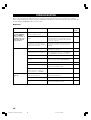
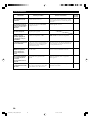
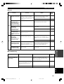
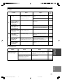
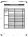
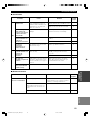
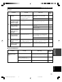
TECHNISCHE GEGEVENS
AUDIO GEDEELTE
• Minimum RMS uitgangsvermogen voor hoofd, midden, achter
1 kHz, 0,1% THV, 6 Ω
[Modellen voor de VS en Canada] ........................................ 70 W
[Overige modellen] ................................................................ 60 W
1 kHz, 0,7% THV, 6 Ω
[Modellen voor de VS en Canada] ........................................ 75 W
[Modellen voor het V.K., Europa, Australië en Korea] ......... 65 W
• DIN Standaard uitgangsvermogen
[Modellen voor Europa]
1 kHz, 0,7% THV, 4 Ω .......................................................... 75 W
• Maximum uitgangsvermogen (EIAJ)
[Modellen voor China, Korea en algemene modellen]
1 kHz, 10% THV, 6 Ω ........................................................... 80 W
• Dynamisch uitgangsvermogen (IHF) 6/4/2 Ω
[Modellen voor de VS en Canada] .......................... 85/100/115 W
[Overige modellen] .................................................... 75/95/105 W
• Frequentierespons
CD, etc naar Hoofd L/R ....................... 10 Hz t/m 100 kHz, –3 dB
• Totale Harmonische Vervorming
1 kHz, 30 W, 6 Ω, Hoofd L/R ...............................................0,06%
• Signaal-ruis verhouding (IHF-A Netwerk)
CD (kortgesloten 250 mV) naar Hoofd L/R, Effect uit
..................................................................................... h100 dB
• Residuele ruis (IHF-A Netwerk)
Hoofd L/R ......................................................... 150 µV of minder
• Kanaalscheiding (1 kHz/10 kHz)
CD, etc (5,1 kΩ getermineerd) naar Hoofd L/R
........................................................................ h60 dB/h45 dB
• Toonregeling (Hoofd L/R)
BASS versterking/verzwakking ............................ ±10 dB/100 Hz
TREBLE versterking/verzwakking ....................... ±10 dB/20 kHz
• Uitgangsvermogen hoofdtelefoon ............................. 300 mV/470 Ω
• Ingangsgevoeligheid
CD, etc .................................................................... 150 mV/47 kΩ
6CH INPUT ............................................................ 150 mV/47 kΩ
• Uitgangsniveau
OUT (REC) ........................................................... 150 mV/1,2 kΩ
OUTPUT SUBWOOFER ............................................. 4 V/1,2 kΩ
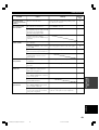
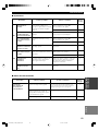
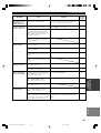
VIDEO GEDEELTE
• Videosignaal-type ....................................................... NTSC of PAL
• Composiet videosignaal-niveau ..................................... 1 Vp-p/75 Ω
• Signaal-ruis verhouding ...................................................... h50 dB
• Frequentierespons (MONITOR OUT) ...... 5 Hz t/m 10 MHz, –3 dB
FM GEDEELTE
• Afstembereik
[Modellen voor de VS en Canada] ................ 87,5 t/m 107,9 MHz
[Overige modellen] .................................... 87,50 t/m 108,00 MHz
• 50 dB Rustgevoeligheid (IHF, 100% mod.)
Mono/Stereo ........................ 2,0 µV (17,3 dBf) /25 µV (39,2 dBf)
• Selectiviteit (400 kHz) ............................................................. 70 dB
• Signaal-ruis verhouding (IHF)
Mono/Stereo .............................................................. 76 dB/70 dB
• Harmonische vervorming (1 kHz)
Mono/Stereo ................................................................. 0,2%/0,3%
• Stereoscheiding (1 kHz) .......................................................... 42 dB
• Frequentierespons ............................. 20 Hz t/m 15 kHz +0,5, –2 dB
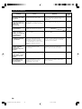
AM GEDEELTE
• Afstembereik ........................................ 530/531 t/m 1710/1611 kHz
• Bruikbare gevoeligheid .................................................... 300 µV/m
ALGEMEEN
• Stroomvoorziening
[Modellen voor de VS en Canada] ...... 120 V wisselstroom/60 Hz
[Modellen voor Australië] ................... 240 V wisselstroom/50 Hz
[Modellen voor het V.K., Europa en Singapore]
.......................................................... 230 V wisselstroom/50 Hz
[Modellen voor Korea] ........................ 220 V wisselstroom/60 Hz
[Modellen voor China] ........................ 220 V wisselstroom/50 Hz
[Algemene modellen]
............................ 110-120V/220-240 V wisselstroom, 50/60 Hz
• Stroomverbruik
[Modellen voor de VS en Canada] ......................... 210 W/280 VA
[Overige modellen] .............................................................. 210 W
Standby-stand ....................................................... 0,8 W of minder
• Afmetingen (b x h x d) ..................................... 435 x 151 x 322 mm
• Gewicht .................................................................................... 8,0 kg
*Technische gegevens kunnen zonder voorafgaande kennisgeving
gewijzigd worden.
01HTR5630_cv_GB-b.p65 03.4.1, 6:51 PM1

1 To assure the finest performance, please read this
manual carefully. Keep it in a safe place for future
reference.
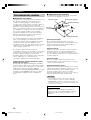
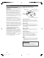
2 Install this sound system in a well ventilated, cool,
dry, clean place — away from direct sunlight, heat
sources, vibration, dust, moisture, and/or cold.
Allow ventilation space of at least 30 cm on the top,
20 cm on the left and right, and 20 cm on the back
of this unit.
3 Locate this unit away from other electrical
appliances, motors, or transformers to avoid
humming sounds.
4
Do not expose this unit to sudden temperature
changes from cold to hot, and do not locate this unit
in a environment with high humidity (i.e. a room with
a humidifier) to prevent condensation inside this unit,
which may cause an electrical shock, fire, damage to
this unit, and/or personal injury.
5 Avoid installing this unit where foreign object may
fall onto this unit and/or this unit may be exposed
to liquid dripping or splashing. On the top of this
unit, do not place:
– Other components, as they may cause damage
and/or discoloration on the surface of this unit.
–
Burning objects (i.e. candles), as they may cause
fire, damage to this unit, and/or personal injury.
– Containers with liquid in them, as they may fall
and liquid may cause electrical shock to the
user and/or damage to this unit.
6 Do not cover this unit with a newspaper, tablecloth,
curtain, etc. in order not to obstruct heat radiation.
If the temperature inside this unit rises, it may
cause fire, damage to this unit, and/or personal
injury.
7 Do not plug in this unit to a wall outlet until all
connections are complete.
8 Do not operate this unit upside-down. It may
overheat, possibly causing damage.
9 Do not use force on switches, knobs and/or cords.
10 When disconnecting the power cord from the wall
outlet, grasp the plug; do not pull the cord.
11 Do not clean this unit with chemical solvents; this
might damage the finish. Use a clean, dry cloth.
12 Only voltage specified on this unit must be used.
Using this unit with a higher voltage than specified
is dangerous and may cause fire, damage to this
unit, and/or personal injury. YAMAHA will not be
held responsible for any damage resulting from use
of this unit with a voltage other than specified.
13
To prevent damage by lightning, disconnect the power
cord from the wall outlet during an electrical storm.
14 Do not attempt to modify or fix this unit. Contact
qualified YAMAHA service personnel when any
service is needed. The cabinet should never be
opened for any reasons.
15 When not planning to use this unit for long periods
of time (i.e. vacation), disconnect the AC power
plug from the wall outlet.
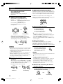
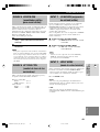
CAUTION: READ THIS BEFORE OPERATING YOUR UNIT.
16 Be sure to read the “TROUBLESHOOTING” section
on common operating errors before concluding that
this unit is faulty.
17 Before moving this unit, press STANDBY/ON to set
this unit in standby mode, and disconnect the AC
power plug from the wall outlet.
18
VOLTAGE SELECTOR (General model only)
The VOLTAGE SELECTOR on the rear panel of this
unit must be set for your local main voltage
BEFORE plugging into the AC main supply.
Voltages are 110V-120V, 220V-240V AC, 50/60 Hz.
This unit is not disconnected from the AC power
source as long as it is connected to the wall outlet,
even if this unit itself is turned off. This state is called
standby mode. In this state, this unit is designed to
consume a very small quantity of power.
WARNING
TO REDUCE THE RISK OF FIRE OR ELECTRIC
SHOCK, DO NOT EXPOSE THIS UNIT TO RAIN
OR MOISTURE.
■ For U.K. customers
If the socket outlets in the home are not suitable for the
plug supplied with this appliance, it should be cut off and
an appropriate 3 pin plug fitted. For details, refer to the
instructions described below.
Note
• The plug severed from the mains lead must be destroyed, as a
plug with bared flexible cord is hazardous if engaged in a live
socket outlet.
■ Special Instructions for U.K. Model
IMPORTANT
THE WIRES IN MAINS LEAD ARE COLOURED
IN ACCORDANCE WITH THE FOLLOWING
CODE:
Blue: NEUTRAL
Brown: LIVE
As the colours of the wires in the mains lead of this
apparatus may not correspond with the coloured
markings identifying the terminals in your plug,
proceed as follows:
The wire which is coloured BLUE must be connected
to the terminal which is marked with the letter N or
coloured BLACK. The wire which is coloured
BROWN must be connected to the terminal which is
marked with the letter L or coloured RED.
Making sure that neither core is connected to the earth
terminal of the three pin plug.
CAUTION
53
Nederlands
AANVULLENDE
INFORMATIE
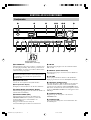
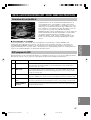
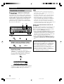
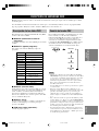
■ PCM (Lineair PCM)
Lineair PCM is een signaalformaat voor
ongecomprimeerde gedigitaliseerde analoge
geluidssignalen, geschikt voor opname, transmissie en
weergave. Dit is de methode waarmee CD’s en DVD
audio discs zijn opgenomen. Het PCM systeem maakt
gebruik van een systeem waarbij het analoge signaal in
zeer kleine stukjes wordt gehakt en per stukje gemeten
wordt (‘bemonsterd’). PCM staat voor “Puls Code
Modulatie” en betekent dat het analoge signaal gecodeerd
wordt als pulsjes en vervolgens o gemoduleerd voor
opname.
■ Bemonsteringsfrequentie en aantal
kwantificeringsbits
Bij het digitaliseren van een analoog audiosignaal wordt
het aantal keren dat het signaal per seconde gemeten
wordt de bemonsteringsfrequentie genoemd, terwijl de
mate van detail waarin het geluid wordt omgezet in een
digitale waarde wordt aangegeven door het aantal
kwantificeringsbits.
De signalen die kunnen worden weergegeven hangen
mede af van de bemonsteringsfrequentie terwijl het
dynamisch bereik, het verschil tussen maximum en
minimum volume, afhangt van het aantal
kwantificeringsbits. Hoe hoger de
bemonsteringsfrequentie, hoe meer frequenties er kunnen
worden weergegeven en hoe hoger het aantal
kwantificeringsbits, hoe beter het volume kan worden
gereproduceerd.
WOORDENLIJST
01RX-V340RDS_cv2-3_GB.p65 03.4.1, 6:51 PM1

1
English
INTRODUCTION
PREPARATION
BASIC
OPERATION
ADVANCED
OPERATION
ADDITIONAL
INFORMATION
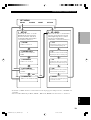
CONTENTS
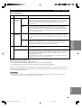
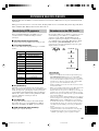
INTRODUCTION
CONTENTS ............................................................ 1
FEATURES ............................................................. 2
GETTING STARTED ............................................ 3
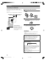
Supplied accessories .................................................. 3
Installing batteries in the remote control ................... 3
CONTROLS AND FUNCTIONS ......................... 4
Front panel ................................................................. 4
Remote control .......................................................... 6
Front panel display .................................................... 8
PREPARATION
CONNECTIONS .................................................... 9
Before connecting components ................................. 9
Connecting video components ................................ 10
Connecting audio components ................................ 11
Connecting the antennas .......................................... 12
Connecting an external decoder .............................. 13
Connecting the speakers .......................................... 14
Connecting the power supply cords ........................ 17
Turning on the power .............................................. 17
BASIC SYSTEM SETTINGS ............................. 18
Using the basic menu .............................................. 18
Setting the unit to match your speaker system ........ 20
Setting speaker output levels (SP LEVEL) ............. 20
BASIC OPERATION
PLAYBACK .......................................................... 21
Input modes and indications .................................... 23
Selecting a sound field program .............................. 24
DIGITAL SOUND FIELD PROCESSING (DSP)
............................................................................ 27
Understanding sound fields ..................................... 27
Hi-Fi DSP programs ................................................ 27
CINEMA-DSP ...................................................... 28
Sound design of CINEMA-DSP ............................. 28
CINEMA-DSP Programs ........................................ 28
Sound field effects ................................................... 30
TUNING ................................................................ 31
Presetting stations .................................................... 32
Selecting a preset station ......................................... 34
RECEIVING RDS STATIONS ........................... 35
Description of RDS data ......................................... 35
Changing the RDS mode ......................................... 35
PTY SEEK function ................................................ 36
EON function .......................................................... 36
SLEEP TIMER ..................................................... 37
RECORDING ....................................................... 38
ADVANCED OPERATION
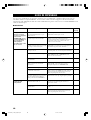
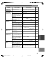
SET MENU ........................................................... 39
Set menu list ............................................................ 39
Adjusting the items on the set menu ....................... 39
SOUND 1 SPEAKER SET (speaker mode settings)
............................................................................. 40
SOUND 2 SP DISTANCE (speaker distance) ........ 42
SOUND 3 LFE LEVEL .......................................... 42
SOUND 4 D. RANGE (dynamic range) ................. 42
SOUND 5 CENTER GEQ
(center graphic equalizer) .................................... 43
SOUND 6 HP TONE CTRL
(headphone tone control) .................................... 43
INPUT 1 I/O ASSIGN (input/output assignment) .. 43
INPUT 2 INPUT MODE (initial input mode) ........ 43
OPTION 1 DISPLAY SET ...................................... 44
OPTION 2 MEM. GUARD (memory guard) ......... 44
OPTION 3 AUDIO MUTE ..................................... 44
SETTING THE SPEAKER LEVELS ................ 45
Adjusting the volume during playback ................... 45
Using the test tone ................................................... 45
ADDITIONAL INFORMATION
SOUND FIELD PROGRAM PARAMETER
EDITING .......................................................... 46
Changing parameter settings ................................... 46
Digital sound field parameter descriptions .............. 47
TROUBLESHOOTING ....................................... 48
GLOSSARY .......................................................... 52
SPECIFICATIONS .............................................. 54
03V340G_01-08_EN(03.4.14)a.p65 03.4.14, 11:48 AM1

2
Manufactured under license from Dolby Laboratories.
“Dolby”, “Pro Logic”, and the double-D symbol are
trademarks of Dolby Laboratories.
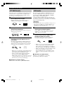
FEATURES
Multi-mode digital sound field processing
◆ Dolby Pro Logic/Dolby Pro Logic II decoder
◆ Dolby Digital/Dolby Digital + Matrix 6.1 Decoder
◆ DTS/DTS + Matrix 6.1 Decoder
◆ CINEMA DSP: Combination of YAMAHA DSP
technology and Dolby Pro Logic, Dolby Digital or
DTS
◆ Virtual CINEMA DSP
◆ SILENT CINEMA DSP
Sophisticated AM/FM Tuner
◆ 40-Station random access preset tuning
◆ Automatic preset tuning
◆ Preset station shifting capability (Preset editing)
Other features
◆ 96 kHz/24-bit D/A converter
◆ Set menu for optimizing this unit for your Audio/
Video system
◆ Test tone generator for easier speaker balance
adjustment
◆ 6-channel external decoder input
◆ Optical and coaxial digital audio signal jacks
◆ Sleep timer
“DTS” and “DTS Digital Surround” are registered
trademarks of Digital Theater Systems, Inc.
Built-in 5-channel power amplifier
◆ Minimum RMS output power
(0.1% THD, 1 kHz, 6Ω)
[U.S.A. and Canada models]
Main: 70 W + 70 W
Center: 70 W
Rear: 70 W + 70 W
[Other models]
Main: 60 W + 60 W
Center: 60 W
Rear: 60 W + 60 W
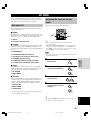
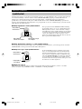
■ About this manual
• y indicates a tip for your operation.
• Some operations can be performed by using either the buttons on the main unit or on the remote control. In cases
when the button names differ between the main unit and the remote control, the button name on the remote control is
given in parentheses.
• This manual is printed prior to production. Design and specifications are subject to change in part for the reason of
the improvement in operativity ability, and others. In this case, the product has priority.
03V340G_01-08_EN(03.4.14)a.p65 03.4.14, 11:48 AM2

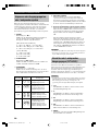
3
English
INTRODUCTION
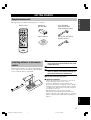
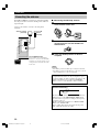
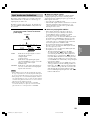
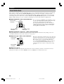
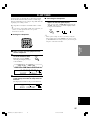
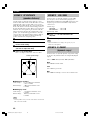
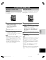
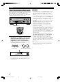
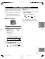
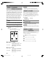
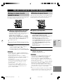
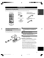
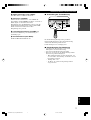
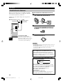
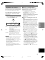
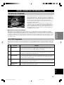
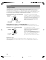
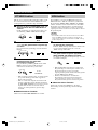
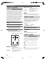
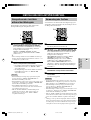
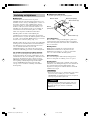
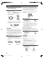
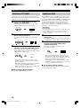
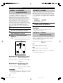
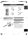
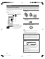
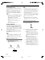
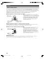
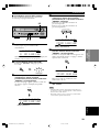
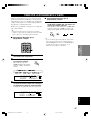
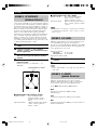
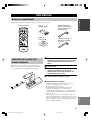
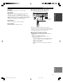
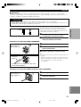
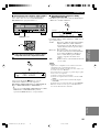
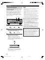
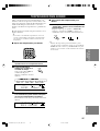
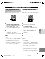
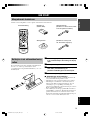
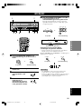
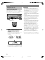
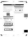
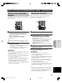
Installing batteries in the remote
control
Insert the batteries in the correct direction by aligning the
+ and – marks on the batteries with the polarity markings
(+ and –) inside the battery compartment.
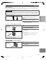
1 Press the tab of the battery compartment
cover and pull it in the direction of the arrow
to open the cover.
2 Remove the cover.
3 Insert the two batteries supplied (AA, R06,
UM-3) according to the polarity markings on
the inside of the battery compartment.
4 Put the cover back into place.
■ Notes on batteries
• Change all of the batteries if you notice a decrease in
the operating range of the remote control.
• Do not use old batteries together with new ones.
• Do not use different types of batteries (such as alkaline
and manganese batteries) together. Read the packaging
carefully as these different types of batteries may have
the same shape and color.
• If the batteries have leaked, dispose of them
immediately. Avoid touching the leaked material or
letting it come into contact with clothing, etc. Clean the
battery compartment thoroughly before installing new
batteries.
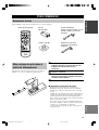
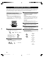
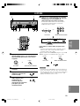
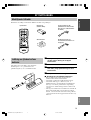
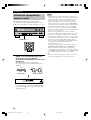
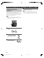
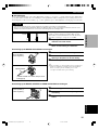
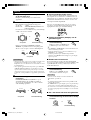
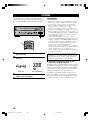
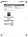
AM loop antenna
(Europe, U.K., Australia and
Singapore models)
Indoor FM antenna
(U.S.A., Canada, China,
Korea and General models)
Batteries (2)
(AA, R06, UM-3)
Remote control
GETTING STARTED
Supplied accessories
After unpacking, check that the following parts are contained.
TEST
PROG PROG
STEREO
LEVEL
SET MENU
TUNER
CD MD/CD-R V-AUX 6CH IN
/DTS 6.1/5.1 NIGHT SLEEP
DVD D-TV/CBL VCR POWER
PRESET
A/B/C/D/E
MUTE
VOLUME
VOLUME
1
2
4
3
03V340G_01-08_EN(03.4.14)a.p65 03.4.14, 11:49 AM3

4
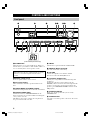
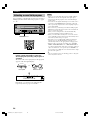
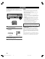
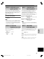
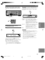
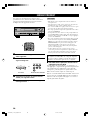
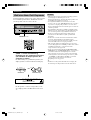
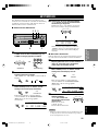
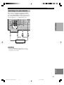
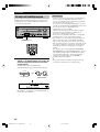
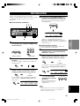
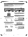
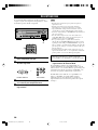
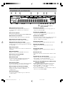
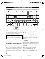
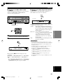
CONTROLS AND FUNCTIONS
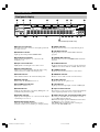
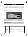
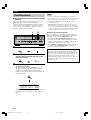
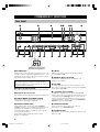
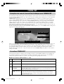
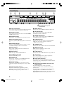
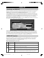
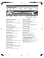
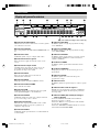
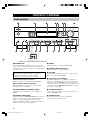
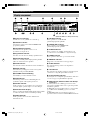
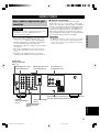
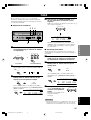
Front panel
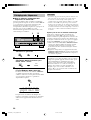
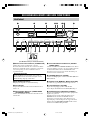
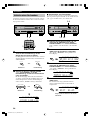
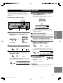
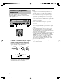
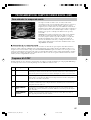
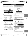
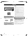
1 STANDBY/ON
Turns the unit on, or sets it in standby mode. When you
turn the unit on, you will hear a click and there will be a 4
to 5-second delay before it can reproduce sound.
Standby mode
In this mode, the unit uses a small amount of power in
order to receive infrared-signals from the remote
control.
2 Remote control sensor
Receives signals from the remote control.
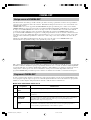
3 Front panel display
Shows information about the operational status of the
unit.
4 TUNING MODE (AUTO/MAN’L MONO)
Switches the tuning mode between automatic and manual.
5 PRESET/TUNING (EDIT)
Switches the function of PRESET/TUNING l / h
between selecting a preset station number and tuning (the
colon (:) turns on or off).
This button is also used to exchange the assignment of
two preset stations with each other.
6 FM/AM
Switches the reception band between FM and AM.
7 MEMORY (MAN’L/AUTO FM)
Stores the current station in memory.
8 VOLUME
Controls the output level of all audio channels.
This does not affect the OUT (REC) level.
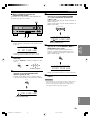
9
SILENT (PHONES jack)
Allows you to enjoy DSP effects when listening with
headphones.
Inserting the plug from your headphones into the
PHONES jack does not affect the sound output from the
speakers. If you wish to stop the signal output to the
speakers, press SPEAKERS ON/OFF so that it is in the
OFF position.
0 SPEAKERS ON/OFF
Turns on or off the speakers that you selected by
SPEAKERS A/B.
q SPEAKERS A/B
Selects the set of main speakers connected to the A or B
terminals.
(U.K. and Europe models only)
VOLUME
STANDBY
/ON
MODE START
PTY SEEK
RDS MODE/FREQ EON
AUTO/MAN`L MONO MAN`L/AUTO FM
TUNING MODE MEMORY
EDIT
PRESET/TUNING FM/AM
SILENT
PHONES
SPEAKERS
AON
BOFF
EFFECT
PRESET/TUNING
SET MENU
A/B/C/D/E
NEXT
PROGRAM
STEREO
BASS/TREBLE
CONTROL
INPUT
6CH INPUTINPUT MODE
12 543 67 8
y
a s fd
MODE START
RDS MODE/FREQ
PTY SEEK
EON
9 0 q w r iute po
03V340G_01-08_EN(03.4.14)a.p65 03.4.14, 11:49 AM4

5
English
INTRODUCTION
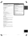
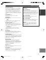
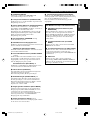
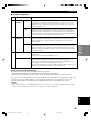
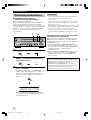
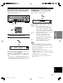
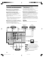
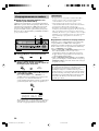
w STEREO (EFFECT)
Switches between normal stereo and DSP effect
reproduction. When you select STEREO, the unit mixes
down all Dolby Digital and DTS signals (except the LFE
channel) as well as those 2-channel signals without
effects, to the main left and right speakers.
e PROGRAM l / h
Select the DSP program.
r A/B/C/D/E
Selects preset station groups A to E when the unit is in
tuner mode.
NEXT
Selects the set menu mode when the unit is not in tuner
mode.
t PRESET/TUNING l / h
Select preset station numbers 1 to 8 when a colon (:) is
displayed in the front panel display.
Select the tuning frequency when a colon (:) is not
displayed when the unit is in tuner mode.
SET MENU –/+
Adjust settings on the set menu when the unit is not in
tuner mode.
y CONTROL
Switches between Bass (low-frequency response) control
mode and Treble (high-frequency response) control mode.
u BASS/TREBLE –/+
Increase or decrease low/high-frequency response when
the unit is in Bass/Treble control mode. The sound
changes 2dB each time you press one of these buttons.
Control range: –10 to +10dB.
i INPUT MODE
Sets the priority for the types of input signals (AUTO,
DTS, ANALOG) received when one component is
connected to two types of input jacks. You cannot set
priority for an audio sources if you have selected 6CH
INPUT as the input source.
o INPUT l / h
Selects the input source you want to listen to or watch.
p 6CH INPUT
Selects the audio source connected to the 6CH INPUT
jacks. This selection takes priority over sources selected
with INPUT (or the input selector buttons on the remote
control).
(U.K. and Europe models only)
a RDS MODE/FREQ
Press this button when the unit is receiving an RDS
station, to cycle the display mode among PS mode,
PTY mode, RT mode, CT mode (if the station offers
those RDS data service) and/or frequency display
mode in turn.
s PTY SEEK MODE
Press this button to set the unit in the PTY SEEK
mode.
d PTY SEEK START
Press this button to begin searching for a station after
the desired program type has been selected in the PTY
SEEK mode.
f EON
Press this button to select a radio program type
(NEWS, INFO, AFFAIRS, SPORT) to tune in
automatically.
CONTROLS AND FUNCTIONS
03V340G_01-08_EN(03.4.14)a.p65 03.4.14, 11:49 AM5

6
TEST
PROG PROG
STEREO
LEVEL
SET MENU
TUNER
CD MD/CD-R V-AUX 6CH IN
/DTS 6.1/5.1 NIGHT SLEEP
DVD D-TV/CBL VCR POWER
PRESET
A/B/C/D/E
MUTE
VOLUME
VOLUME
2
8
1
0
3
5
9
7
4
6
r
y
e
q
w
t
u
i
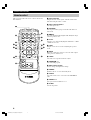
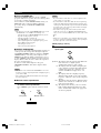
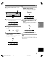
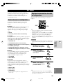
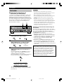
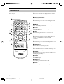
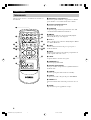
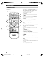
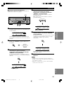
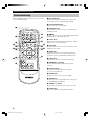
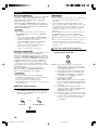
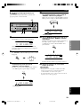
Remote control
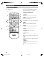
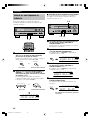
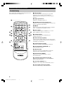
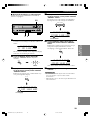
1 Infrared emitter
Outputs infrared control signals. Aim this emitter at the
unit when using the remote control.
2 Input selector buttons
Select the input source.
3 A/B/C/D/E
Selects preset station groups A to E when the unit is in
tuner mode.
4 q/DTS
Selects the built-in Dolby Digital, DTS, Dolby Pro Logic
or Pro Logic II decoder.
5 6.1/5.1
Switches on or off the Dolby Digital + Matrix 6.1 or DTS
+ Matrix 6.1 decoder.
6 TEST
Outputs a test tone for use when adjusting the speaker
levels.
7 MUTE
Mutes the sound. Press again to restore the audio output
to the previous volume level.
8 LEVEL
Selects the effect speaker channel to adjust.
9 PROGRAM –/+
Select the DSP program.
0 Multi control section
Used to change and implement settings.
q POWER
Turns the unit on, or sets it in standby mode.
w 6CH IN
Selects the audio source connected to the 6CH INPUT
jacks.
e PRESET –/+
Select preset station numbers 1 to 8.
r SLEEP
Sets the sleep timer.
CONTROLS AND FUNCTIONS
This section describes the remote control controls and
their functions.
03V340G_01-08_EN(03.4.14)a.p65 03.4.14, 11:49 AM6

7
English
INTRODUCTION
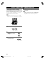
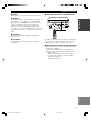
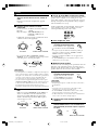
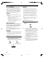
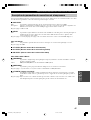
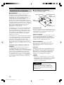
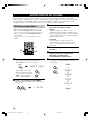
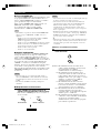
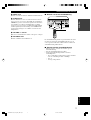
Approximately 6 m (20 feet)
■ Using the remote control
The remote control transmits a directional infrared beam.
Be sure to aim the remote control directly at the remote
control sensor on the main unit during operation.
■ Handling the remote control
• Do not spill water or other liquids on the remote
control.
• Do not drop the remote control.
• Do not leave or store the remote control in the
following types of conditions:
– high humidity or temperature such as near a heater,
stove or bath;
– dusty places; or
– in places subject to extremely low temperatures.
VOLUME
STANDBY
/ON
AUTO/MAN`L MONO MAN`L/AUTO FM
TUNING MODE MEMORY
EDIT
PRESET/TUNING FM/AM
SILENT
PHONES
SPEAKERS
AON
BOFF
EFFECT
PRESET/TUNING
SET MENU
A/B/C/D/E
NEXT
PROGRAM
STEREO
BASS/TREBLE
CONTROL
INPUT
6CH INPUTINPUT MODE
30° 30°
CONTROLS AND FUNCTIONS
t NIGHT
Sets the unit in night listening mode.
y STEREO
Switches between normal stereo and DSP effect
reproduction. When you select STEREO the unit mixes
down all Dolby Digital and DTS signals (except the LFE
channel) as well as those 2-channel signals without effect
sounds, to the main left and right speakers.
u VOLUME +/–
Increases or decreases the volume level.
i SET MENU
Selects the set menu mode.
03V340G_01-08_EN(03.4.14)a.p65 03.4.14, 11:49 AM7

8
V-AUXVCR
D-TV/CBL
DVD
MD/CD-R
TUNER CD
MATRIX
DIGITAL
PL
PL
PCM
SILENT
DSP
HiFi
NIGHT
VIRTUAL
AUTO
STEREO
SLEEP
VOLUME
MUTE
MEMORYTUNED
L C R
RLLFE RC RR
~~~~~~~~~~~~~~
dB
ft
CTRTPTYPS
HOLDPTYEON
13
45
8
7
62
90qw yer uiop
a
t
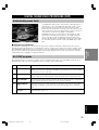
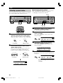
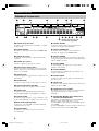
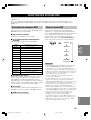
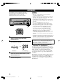
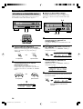
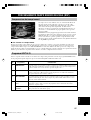
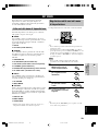
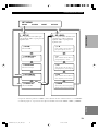
1 Processor indicators
The indicators for the various decoders light up when the
decoders are in use.
2 VIRTUAL indicator
Lights up when using Virtual CINEMA DSP.
3 Headphones indicator
Lights up when headphones are connected to the
headphone jack.
4 Input source indicator
Highlights the current input source with a cursor.
5 Sound field indicator
Displays the sound field management the unit is using
when you listen to a DSP sound field program.
6 AUTO indicator
Shows that this unit is in the automatic tuning mode.
7 MUTE indicator
Flashes while the MUTE function is on.
8 VOLUME level indicator
Indicates the volume level.
9 PCM indicator
Lights up when this unit is reproducing PCM (pulse code
modulation) digital audio signals.
0 SILENT indicator
Lights up when headphones are connected and the digital
sound field processor is on.
q Multi-information display
Shows the current DSP program name and other
information when you are adjusting or changing settings.
w NIGHT indicator
Lights up when the unit is set to night listening mode.
e HiFi DSP indicator
Lights up when you select a Hi-Fi DSP sound field
program.
r CINEMA DSP indicator
Lights up when you select a CINEMA DSP sound field
program.
t STEREO indicator
Lights up when the unit is receiving a strong signal from
a FM stereo broadcast while the “AUTO” indicator is lit.
y TUNED indicator
Lights up when this unit is tuned to a radio station.
u MEMORY indicator
Flashes to show a station can be stored in memory.
i SLEEP indicator
Lights up while the sleep timer is on.
o LFE indicator
Lights up when the input signal contains an LFE signal.
p Input channel indicator
The indicators for the appropriate sound channels light up
when a digital signal from a source is played back.
a RDS indicator (U.K. and Europe models only)
The name(s) of the RDS data offered by the currently
received RDS station light(s) up.
EON indicator lights up when an RDS station that offers
the EON data service is being received.
PTY HOLD indicator lights up while searching for
stations in the PTY SEEK mode.
Front panel display
(U.K. and Europe models only)
CONTROLS AND FUNCTIONS
03V340G_01-08_EN(03.4.14)a.p65 03.4.14, 11:49 AM8

9
English
PREPARATION
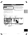
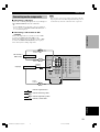
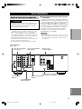
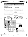
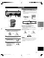
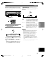
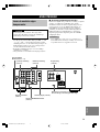
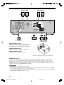
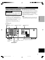
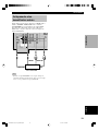
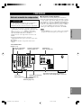
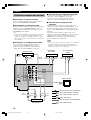
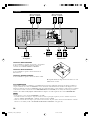
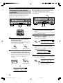
CONNECTIONS
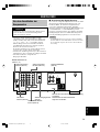
Before connecting components
CAUTION
Do not connect this unit or other components to the
mains power until all connections between the
components have been completed.
• Be sure all connections are made correctly, that is to
say L (left) to L, R (right) to R, “+” to “+” and “–” to
“–”. Some components require different connection
methods and have different jack names. Refer to the
operation instructions for each component you wish to
connect to this unit.
• After you have completed all connections, check them
again to make sure they are correct.
• The jack names correspond to the names on the input
selector.
■ Connecting to digital jacks
This unit has digital jacks for direct transmission of
digital signals through either a coaxial or fiber optic
cable. You can use the digital jacks to input PCM, Dolby
Digital and DTS bitstreams. Use digital connections if
you wish to enjoy the multi-channel sound track of DVD
material, etc. with DSP effects. Both digital input jacks
are acceptable for 96 kHz sampling digital signals.
Note
• The OPTICAL jack on this unit conform to the EIA standard.
If you use a fiber optic cable that does not conform to this
standard this unit may not function properly.
6CH INPUT jacks
(page 13)
DIGITAL INPUT jacks
(pages 9 – 11)
Antenna input terminals
(page 12)
Speaker terminals
(page 16)
Video component jacks
(page 10)
Audio component jacks
(page 11)
SUBWOOFER OUTPUT
jack (page 16)
This jack is reserved for factory use.
Do not connect any equipment to this jack.
AUDIO
LR
2
1
AUDIO VIDEO TUNER SPEAKERS
CLASS 2 WIRING
LR
LR
LR
LR
CD DVD
AM
MAIN
A
MAIN
REAR
(
SURROUND
)
CENTER
B
ANT
GND
FM
ANT
IN
(PLAY)
MAIN
DVD
CD
DIGITAL
INPUT
SUB
WOOFER
CENTER
SUB
WOOFER
MONITOR
OUT
SURROUND
OPTICAL
COAXIAL
OUT
(REC)
MD
/CD-R
D-TV
/CBL
V-AUX
IN
VCR
OUT
6CH INPUT OUTPUT
75Ω UNBAL.
MAIN A OR B : 6Ω MIN./SPEAKER
CENTER : 6Ω MIN./SPEAKER
REAR
: 6Ω MIN./SPEAKER
04V340G_09-18_EN(03.3.12)a.p65 03.4.14, 11:49 AM9

10
AUDIO
LR
2
1
AUDIO VIDEO TUNER
LR
CD DVD
AM
ANT
GND
FM
ANT
IN
(PLAY)
MAIN
DVD
CD
DIGITAL
INPUT
SUB
WOOFER
CENTER
SUB
WOOFER
MONITOR
OUT
SURROUND
OPTICAL
COAXIAL
OUT
(REC)
MD
/CD-R
D-TV
/CBL
V-AUX
IN
VCR
OUT
6CH INPUT OUTPUT
75Ω UNBAL.
VIDEO
INPUT
AUDIO
OUTPUT
LR
AUDIO
INPUT
LR
O
OPTICAL
OUTPUT
VIDEO
OUTPUT
AUDIO
OUTPUT
L
V
R
V V
AUDIO
OUTPUT
L R
VIDEO
OUTPUT
V
AUDIO
OUTPUT
L R
VIDEO
OUTPUT
V
V
VIDEO
INPUT
VIDEO
OUTPUT
O
L
R
V
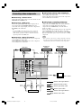
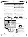
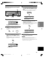
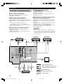
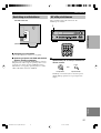
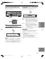
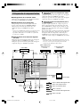
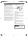
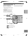
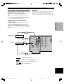
Connecting video components
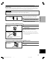
■ Connecting a video monitor
Connect the video input jack on your video monitor to the
MONITOR OUT VIDEO jack.
■ Connecting a DVD player
Connect the optical digital audio signal output jack on
your component to the DIGITAL INPUT jack and
connect the video signal output jack on the component to
the VIDEO jack on this unit.
y
• Use the AUDIO jacks on this unit for a video component
which does not have optical digital output jack. However,
multi-channel reproduction cannot be obtained with audio
signals input from the AUDIO jacks.
■ Connecting a digital TV/cable TV
Connect the video signal output jack on your component
to the VIDEO jack on this unit.
Connect the audio signal output jacks on the component
to the AUDIO jacks on this unit.
■ Connecting another video component
Connect the video signal output jack on your component
to the VIDEO jack on this unit.
Connect the audio signal output jacks on the component
to the AUDIO jacks on this unit.
■ Connecting a recording component
Connect the audio signal input jacks on your video
component to the AUDIO OUT jacks on this unit. Then
connect the video signal input jack on the video
component to the VIDEO OUT jack on this unit for
picture recording.
Connect the audio signal output jacks on your component
to the AUDIO IN jacks on this unit. Then connect the
video signal output jack on the component to the VIDEO
IN jack on this unit to play a source from your recording
component.
Note
• Once you have connected a recording component to this unit,
keep its power turned on while using this unit. If the power is
off, this unit may distort the sound from other components.
indicates right analog cables
indicates left analog cables
indicates audio signal direction
Video monitor
VCR
DVD player
TV/digital TV/
cable TV
CONNECTIONS
Another video
component
indicates optical cables
indicates video signal direction
indicates video cables
04V340G_09-18_EN(03.3.12)a.p65 03.4.14, 11:49 AM10

11
English
PREPARATION
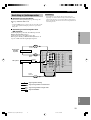
Connecting audio components
■ Connecting a CD player
Connect the coaxial digital output jack on your CD player
to the DIGITAL INPUT CD jack on this unit.
y
• Use the AUDIO jacks on this unit to connect to a CD player
that does not have a COAXIAL DIGITAL OUTPUT jack, or
to record from CD players.
■ Connecting a CD recorder or MD
recorder
Connect the input jacks on your CD recorder or MD
recorder to the MD/CD-R OUT (REC) jacks.
Connect the output jacks on your CD recorder or MD
recorder to the MD/CD-R IN (PLAY) jacks to play a
source from your recording component.
indicates right analog cables
indicates left analog cables
indicates signal direction
CD player
indicates coaxial cables
CD recorder or
MD recorder
CONNECTIONS
AUDIO
LR
2
1
AUDIO VIDEO TUNER
LR
CD DVD
AM
ANT
GND
FM
ANT
IN
(PLAY)
MAIN
DVD
CD
DIGITAL
INPUT
SUB
WOOFER
CENTER
SUB
WOOFER
MONITOR
OUT
SURROUND
OPTICAL
COAXIAL
OUT
(REC)
MD
/CD-R
D-TV
/CBL
V-AUX
IN
VCR
OUT
6CH INPUT OUTPUT
75Ω UNBAL.
C
L
R
AUDIO
INPUT
L
R
AUDIO
OUTPUT
L
R
AUDIO
OUTPUT
L
R
COAXIAL
OUTPUT
C
Note
• Once you have connected a recording component to this unit,
keep its power turned on while using this unit. If the power is
off, this unit may distort the sound from other components.
04V340G_09-18_EN(03.3.12)a.p65 03.4.14, 11:49 AM11

12
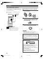
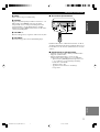
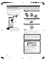
■ Connecting the AM loop antenna
1 Set up the AM loop antenna, then connect it
to the terminals on this unit.
2 Press and hold the tab to insert the AM loop
antenna lead wires into the AM ANT and
GND terminals.
3 Orient the AM loop antenna for the best
reception.
Notes
• The AM loop antenna should be placed away from this unit.
• The AM loop antenna should always be connected, even if an
outdoor AM antenna is connected to this unit.
A properly installed outdoor antenna provides clearer
reception than an indoor one. If you experience poor
reception quality, an outdoor antenna may improve the
quality. Consult the nearest authorized YAMAHA
dealer or service center about the outdoor antennas.
FREQUENCY STEP switch
(General model only)
Because the inter-station frequency spacing differs in
different areas, set the FREQUENCY STEP switch
(located on the rear panel) according to the frequency
spacing in your area.
North, Central and South America: 100 kHz/10 kHz
Other areas: 50 kHz/9 kHz
Before setting this switch, disconnect the AC power
plug of this unit from the AC outlet.
Ground (GND terminal)
For maximum safety and minimum
interference, connect the antenna GND
terminal to a good earth ground. A good
earth ground is a metal stake driven into
moist earth.
Indoor FM
antenna
(included)
AM loop antenna
(included)
Connecting the antennas
Both AM and FM indoor antennas are included with this
unit. In general, these antennas should provide sufficient
signal strength.
Connect each antenna correctly to the designated
terminals.
CONNECTIONS
D
EO TUNER
AM
ANT
GND
FM
ANT
MONITOR
OUT
75Ω UNBAL.
50 kHz/ 9kHz
100 kHz/10kHz
FM/AM
FREQUENCY STEP
04V340G_09-18_EN(03.3.12)a.p65 03.4.14, 11:49 AM12

13
English
PREPARATION
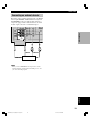
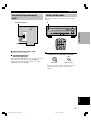
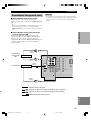
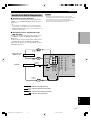
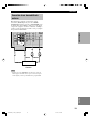
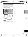
Connecting an external decoder
This unit is equipped with 6 additional input jacks (MAIN
left and right, CENTER, SURROUND left and right and
SUBWOOFER) for discrete multi-channel input from a
component equipped with a multi-channel decoder and 6
channel output jacks such as a DVD/SACD player.
Note
• When you select 6CH INPUT as the input source, the unit
automatically turns off the digital sound field processor, and
you cannot use DSP programs.
CONNECTIONS
DVD/SACD player
2
1
FM
ANT
MAIN
DVD
CD
DIGITAL
INPUT
SUB
WOOFER
CENTER
SUB
WOOFER
MONITOR
OUT
SURROUND
OPTICAL
COAXIAL
OUT
(REC)
/CD
-
R
V-AUX
IN
VCR
OUT
6CH INPUT OUTPUT
75Ω UNBAL.
L R
LR
SUBWOOFER MAIN
CENTER SURROUND
SUBWOOFER MAIN
CENTER SURROUND
04V340G_09-18_EN(03.3.12)a.p65 03.4.14, 11:49 AM13

14
Connecting the speakers
■ Speakers
This unit has been designed to provide the best sound-
field quality with a 5-speaker system, using main left and
right speakers, rear left and right speakers and a center
speaker. If you use different brands of speakers (with
different tonal qualities) in your system, the tone of a
moving human voice and other types of sound may not
shift smoothly. We recommend that you use speakers
from the same manufacturer or speakers with the same
tonal quality.
The main speakers are used for the main source sound
plus effect sounds. They will probably be the speakers
from your present stereo system. The rear speakers are
used for effect and surround sounds. The center speaker is
for the center sounds (dialog, vocals, etc.).
The main speakers should be high-performance models
and have enough power-handling capacity to accept the
maximum output of your audio system. The other
speakers do not have to be equal to the main speakers. For
precise sound localization, however, it is ideal to use the
models of equivalent performance with the main
speakers.
Use of a subwoofer expands your sound field
It is also possible to further expand your system with the
addition of a subwoofer. The use of a subwoofer is
effective not only for reinforcing bass frequencies from
any or all channels, but also for reproducing the LFE
(low-frequency effect) channel with high fidelity when
playing back Dolby Digital or DTS signals. The
YAMAHA Active Servo Processing Subwoofer System is
ideal for natural and lively bass reproduction.
CONNECTIONS
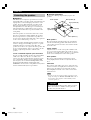
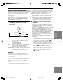
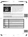
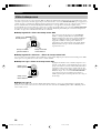
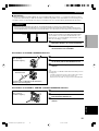
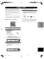
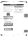
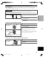
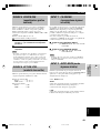
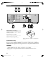
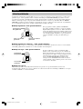
■ Speaker placement
Refer to the following diagram when you place the
speakers.
Main speakers
Place the main left and right speakers an equal distance
from the ideal listening position. The distance between
each speaker and each side of the video monitor should
also be the same.
Center speaker
Align the front face of the center speaker with the front
face of your video monitor. Place the speaker as close to
the monitor as possible (such as directly over or under the
monitor) and centrally between the main speakers.
Rear speakers
Place these speakers behind your listening position,
facing slightly inwards, about 1.8 m (6 feet) above the
floor.
Subwoofer
The position of the subwoofer is not so critical, because
low bass sounds are not highly directional. However, it is
better to place the subwoofer near the main speakers.
Turn it slightly toward the center of the room to reduce
wall reflections.
Note
• If you do not use any of effect speakers (rear and/or center),
change the settings of “SOUND 1 SPEAKER SET” items at
the set menu to direct signals to other terminals you have
connected speakers to.
CAUTION
Use magnetically shielded speakers. If these speakers
still create interference with the monitor, place the
speakers away from the monitor.
Main
speaker (L)
1.8 m (6 feet)
Rear speaker (L)
Rear speaker (R)
Subwoofer
Main speaker (R)
Center speaker
04V340G_09-18_EN(03.3.12)a.p65 03.4.14, 11:49 AM14

15
English
PREPARATION
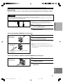
10 mm (3/8”)
Red: positive (+)
Black: negative (–)
Banana plug
CONNECTIONS
12
■ Connections
Be sure to connect the left channel (L), right channel (R), “+” (red) and “–” (black) in accordance with the markers on
this unit, the speakers, and the speaker cables. If the connections are faulty, no sound will be heard from the speakers,
and if the polarity of the speaker connections is incorrect, the sound will be unnatural and lack bass.
CAUTION
• Use speakers with the specified impedance shown on the rear panel of this unit.
• Do not let the bare speaker wires touch each other or any metal part of this unit. This could damage this unit and/
or the speakers.
A speaker cord is actually a pair of insulated cables
running side by side. One cable is colored or shaped
differently, perhaps with a stripe, groove or ridge.
1 Remove approximately 10 mm (3/8”) of
insulation from each of the speaker cables.
2 Twist the exposed wires of the cable
together to prevent short circuits.
1 Unscrew the knob.
2 Insert one bare wire into the hole in the side
of each terminal.
3 Tighten the knob to secure the wire.
y
(With the exception of U.K., Europe, Korea, and Singapore
models)
• You can also use banana plug connectors. First, tighten the
knob and then insert the banana plug connector into the end of
the corresponding terminal.
1 Press and open the tab.
2 Insert one bare wire into the hole of each
terminal.
3 Release the tab to secure the wire.
(With the exception of U.K., Europe, Korea, and
Singapore models)
Connecting to the MAIN A SPEAKERS terminals
3
1
2
Red: positive (+)
Black: negative (–)
Connecting to the MAIN B, CENTER and REAR SPEAKERS terminals
1
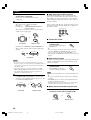
2
3
04V340G_09-18_EN(03.3.12)a.p65 03.4.14, 11:49 AM15

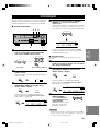
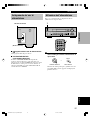
16
Subwoofer
system
Main B speaker
Center
speaker
Right
Rear speaker
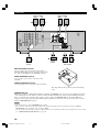
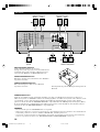
SUBWOOFER jack
When using a subwoofer with built-in amplifier, including the YAMAHA Active Servo Processing Subwoofer System,
connect the input jack of the subwoofer system to this jack. This unit will direct low bass signals distributed from the
main, center and/or rear channels to this jack in accordance with your SPEAKER SET selections. The LFE (low-
frequency effect) signals generated when Dolby Digital or DTS is decoded are also directed to this jack in accordance
with your SPEAKER SET selections.
Notes
• The cut-off frequency of the SUBWOOFER jack is 90 Hz.
• If you do not use a subwoofer, allocate the signals to the main left and right speakers by changing the setting of “SOUND 1
SPEAKER SET” item “1D BASS” on the set menu to MAIN.
• Use the control on the subwoofer to adjust its volume level. You can also adjust the volume level by using this unit’s remote control
(see “SETTING THE SPEAKER LEVELS” on page 45).
Right Left
Main A speaker
Right Left Left
MAIN SPEAKERS terminals
You can connect up to two speaker systems to these
terminals. When using only one speaker system, connect
it to either of the MAIN A or the MAIN B terminals.
REAR SPEAKERS terminals
A rear speaker system can be connected to these
terminals.
CENTER SPEAKER terminals
A center speaker can be connected to these terminals.
CONNECTIONS
The diagram shows the speaker layout in the listening
room.
AUDIO
LR
2
1
AUDIO VIDEO TUNER SPEAKERS
CLASS 2 WIRING
LR
LR
LR
LR
CD DVD
AM
MAIN
A
MAIN
REAR
(
SURROUND
)
CENTER
B
ANT
GND
FM
ANT
IN
(PLAY)
MAIN
DVD
CD
DIGITAL
INPUT
SUB
WOOFER
CENTER
SUB
WOOFER
MONITOR
OUT
SURROUND
OPTICAL
COAXIAL
OUT
(REC)
MD
/CD-R
D-TV
/CBL
V-AUX
IN
VCR
OUT
6CH INPUT OUTPUT
75Ω UNBAL.
MAIN A OR B : 6Ω MIN./SPEAKER
CENTER : 6Ω MIN./SPEAKER
REAR
: 6Ω MIN./SPEAKER
3
65
21
4
1
2
4
3
6
5
04V340G_09-18_EN(03.3.12)a.p65 03.4.14, 11:49 AM16

17
English
PREPARATION
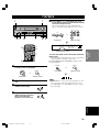
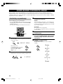
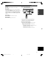
Connecting the power supply
cords
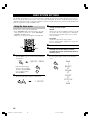
■ Connecting the AC power cord
Plug in this unit to a wall outlet.
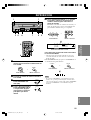
■ VOLTAGE SELECTOR
(General model only)
The VOLTAGE SELECTOR on the rear panel of this unit
must be set for your local main voltage BEFORE
plugging into the AC main supply. Voltages are 110V-
120V/220V-240V AC, 50/60 Hz.
VOLTAGE SELECTOR
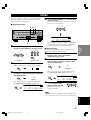
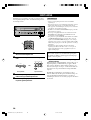
Turning on the power
When all connections are complete, turn on the power of
this unit.
1 Press STANDBY/ON (POWER on the remote
control) to turn on the power of this unit.
The level of the main volume, and then the current
DSP program name appear on the front panel
display.
or
Remote control
Front panel
(General model)
CONNECTIONS
L
REAR
U
RROUND
)
110V-120V
220V-240V
N
./SPEAKER
N
./SPEAKER
VOLTAGE
SELECTOR
VOLUME
STANDBY
/ON
AUTO/MAN`L MONO MAN`L/AUTO FM
TUNING MODE MEMORY
EDIT
PRESET/TUNING FM/AM
SILENT
PHONES
SPEAKERS
AON
BOFF
EFFECT
PRESET/TUNING
SET MENU
A/B/C/D/E
NEXT
PROGRAM
STEREO
BASS/TREBLE
CONTROL
INPUT
6CH INPUTINPUT MODE
1
TEST
PROG PROG
STEREO
TUNER
CD MD/CD-R V-AUX 6CH IN
/D T S 6.1/5.1 NIGHT SLEEP
DVD D-TV/CBL VCR POWER
PRESET
A/B/C/D/E
VOLUME
1
STANDBY
/ON
POWER
04V340G_09-18_EN(03.3.12)a.p65 03.4.14, 11:49 AM17

18
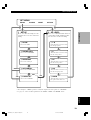
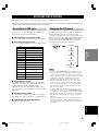
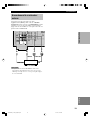
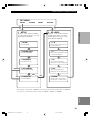
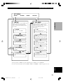
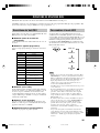
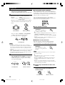
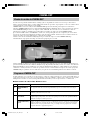
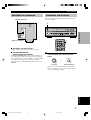
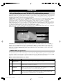
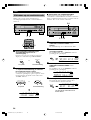
Using the basic menu
Use the remote control to make adjustments.
• Press SPEAKERS A/B on the front panel to select the
main speakers you want to use, and set SPEAKERS
ON/OFF to the ON position.
• Make sure you disconnect headphones from this unit.
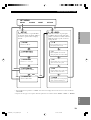
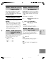
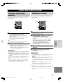
1 Press SET MENU.
“BASIC MENU” appears on the front panel display,
as shown here.
If the front panel display
changes to show anything
other than “BASIC MENU”,
press u until it displays
“BASIC MENU”.
2 Press –/+ to enter into the BASIC menu.
The front panel display changes as shown here:
BASIC SYSTEM SETTINGS
The “BASIC” menu allows you to set some of the basic “SOUND” menu parameters with a minimum of effort. If you
wish to configure the unit more precisely to suit your listening environment, use the more detailed parameters from the
“SOUND” menu instead of those under the “BASIC” menu (See page 40). Altering any parameters in the BASIC menu
will reset all parameters in the “SOUND” menu.
TEST
PROG PROG
STEREO
LEVEL
SET MENU
MUTE
VOLUME
VOLUME
1
2,4
3,6
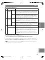
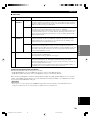
3 Press u / d to change the display to the
setting you want to alter.
SETUP
Changes the speaker and amplifier settings to suit the
size of the room you are using. Refer to “Setting the
unit to match your speaker system” on page 20 for
more information.
SP LEVEL
Adjusts the output levels of the speakers.
Refer to “Setting speaker output levels” on page 20
for more information.
4 Press –/+ to enter the desired setting mode.
5 Change the unit settings to suit your
listening environment. When you have
finished, the unit will automatically return to
the basic menu.
6 Press u / d to exit from the set menu.
The front panel display changes in the following
order:
BASIC MENU
1 SETUP
↑
BASIC
↓↑
SOUND
↓↑
INPUT
↓↑
OPTION
↓
Exit
Exit
SET MENU
05V340G_19-21_EN(03.3.18)a.p65 03.4.14, 11:49 AM18
Sayfa yükleniyor ...
Sayfa yükleniyor ...
Sayfa yükleniyor ...
Sayfa yükleniyor ...
Sayfa yükleniyor ...
Sayfa yükleniyor ...
Sayfa yükleniyor ...
Sayfa yükleniyor ...
Sayfa yükleniyor ...
Sayfa yükleniyor ...
Sayfa yükleniyor ...
Sayfa yükleniyor ...
Sayfa yükleniyor ...
Sayfa yükleniyor ...
Sayfa yükleniyor ...
Sayfa yükleniyor ...
Sayfa yükleniyor ...
Sayfa yükleniyor ...
Sayfa yükleniyor ...
Sayfa yükleniyor ...
Sayfa yükleniyor ...
Sayfa yükleniyor ...
Sayfa yükleniyor ...
Sayfa yükleniyor ...
Sayfa yükleniyor ...
Sayfa yükleniyor ...
Sayfa yükleniyor ...
Sayfa yükleniyor ...
Sayfa yükleniyor ...
Sayfa yükleniyor ...
Sayfa yükleniyor ...
Sayfa yükleniyor ...
Sayfa yükleniyor ...
Sayfa yükleniyor ...
Sayfa yükleniyor ...
Sayfa yükleniyor ...
Sayfa yükleniyor ...
Sayfa yükleniyor ...
Sayfa yükleniyor ...
Sayfa yükleniyor ...
Sayfa yükleniyor ...
Sayfa yükleniyor ...
Sayfa yükleniyor ...
Sayfa yükleniyor ...
Sayfa yükleniyor ...
Sayfa yükleniyor ...
Sayfa yükleniyor ...
Sayfa yükleniyor ...
Sayfa yükleniyor ...
Sayfa yükleniyor ...
Sayfa yükleniyor ...
Sayfa yükleniyor ...
Sayfa yükleniyor ...
Sayfa yükleniyor ...
Sayfa yükleniyor ...
Sayfa yükleniyor ...
Sayfa yükleniyor ...
Sayfa yükleniyor ...
Sayfa yükleniyor ...
Sayfa yükleniyor ...
Sayfa yükleniyor ...
Sayfa yükleniyor ...
Sayfa yükleniyor ...
Sayfa yükleniyor ...
Sayfa yükleniyor ...
Sayfa yükleniyor ...
Sayfa yükleniyor ...
Sayfa yükleniyor ...
Sayfa yükleniyor ...
Sayfa yükleniyor ...
Sayfa yükleniyor ...
Sayfa yükleniyor ...
Sayfa yükleniyor ...
Sayfa yükleniyor ...
Sayfa yükleniyor ...
Sayfa yükleniyor ...
Sayfa yükleniyor ...
Sayfa yükleniyor ...
Sayfa yükleniyor ...
Sayfa yükleniyor ...
Sayfa yükleniyor ...
Sayfa yükleniyor ...
Sayfa yükleniyor ...
Sayfa yükleniyor ...
Sayfa yükleniyor ...
Sayfa yükleniyor ...
Sayfa yükleniyor ...
Sayfa yükleniyor ...
Sayfa yükleniyor ...
Sayfa yükleniyor ...
Sayfa yükleniyor ...
Sayfa yükleniyor ...
Sayfa yükleniyor ...
Sayfa yükleniyor ...
Sayfa yükleniyor ...
Sayfa yükleniyor ...
Sayfa yükleniyor ...
Sayfa yükleniyor ...
Sayfa yükleniyor ...
Sayfa yükleniyor ...
Sayfa yükleniyor ...
Sayfa yükleniyor ...
Sayfa yükleniyor ...
Sayfa yükleniyor ...
Sayfa yükleniyor ...
Sayfa yükleniyor ...
Sayfa yükleniyor ...
Sayfa yükleniyor ...
Sayfa yükleniyor ...
Sayfa yükleniyor ...
Sayfa yükleniyor ...
Sayfa yükleniyor ...
Sayfa yükleniyor ...
Sayfa yükleniyor ...
Sayfa yükleniyor ...
Sayfa yükleniyor ...
Sayfa yükleniyor ...
Sayfa yükleniyor ...
Sayfa yükleniyor ...
Sayfa yükleniyor ...
Sayfa yükleniyor ...
Sayfa yükleniyor ...
Sayfa yükleniyor ...
Sayfa yükleniyor ...
Sayfa yükleniyor ...
Sayfa yükleniyor ...
Sayfa yükleniyor ...
Sayfa yükleniyor ...
Sayfa yükleniyor ...
Sayfa yükleniyor ...
Sayfa yükleniyor ...
Sayfa yükleniyor ...
Sayfa yükleniyor ...
Sayfa yükleniyor ...
Sayfa yükleniyor ...
Sayfa yükleniyor ...
Sayfa yükleniyor ...
Sayfa yükleniyor ...
Sayfa yükleniyor ...
Sayfa yükleniyor ...
Sayfa yükleniyor ...
Sayfa yükleniyor ...
Sayfa yükleniyor ...
Sayfa yükleniyor ...
Sayfa yükleniyor ...
Sayfa yükleniyor ...
Sayfa yükleniyor ...
Sayfa yükleniyor ...
Sayfa yükleniyor ...
Sayfa yükleniyor ...
Sayfa yükleniyor ...
Sayfa yükleniyor ...
Sayfa yükleniyor ...
Sayfa yükleniyor ...
Sayfa yükleniyor ...
Sayfa yükleniyor ...
Sayfa yükleniyor ...
Sayfa yükleniyor ...
Sayfa yükleniyor ...
Sayfa yükleniyor ...
Sayfa yükleniyor ...
Sayfa yükleniyor ...
Sayfa yükleniyor ...
Sayfa yükleniyor ...
Sayfa yükleniyor ...
Sayfa yükleniyor ...
Sayfa yükleniyor ...
Sayfa yükleniyor ...
Sayfa yükleniyor ...
Sayfa yükleniyor ...
Sayfa yükleniyor ...
Sayfa yükleniyor ...
Sayfa yükleniyor ...
Sayfa yükleniyor ...
Sayfa yükleniyor ...
Sayfa yükleniyor ...
Sayfa yükleniyor ...
Sayfa yükleniyor ...
Sayfa yükleniyor ...
Sayfa yükleniyor ...
Sayfa yükleniyor ...
Sayfa yükleniyor ...
Sayfa yükleniyor ...
Sayfa yükleniyor ...
Sayfa yükleniyor ...
Sayfa yükleniyor ...
Sayfa yükleniyor ...
Sayfa yükleniyor ...
Sayfa yükleniyor ...
Sayfa yükleniyor ...
Sayfa yükleniyor ...
Sayfa yükleniyor ...
Sayfa yükleniyor ...
Sayfa yükleniyor ...
Sayfa yükleniyor ...
Sayfa yükleniyor ...
Sayfa yükleniyor ...
Sayfa yükleniyor ...
Sayfa yükleniyor ...
Sayfa yükleniyor ...
Sayfa yükleniyor ...
Sayfa yükleniyor ...
Sayfa yükleniyor ...
Sayfa yükleniyor ...
Sayfa yükleniyor ...
Sayfa yükleniyor ...
Sayfa yükleniyor ...
Sayfa yükleniyor ...
Sayfa yükleniyor ...
Sayfa yükleniyor ...
Sayfa yükleniyor ...
Sayfa yükleniyor ...
Sayfa yükleniyor ...
Sayfa yükleniyor ...
Sayfa yükleniyor ...
Sayfa yükleniyor ...
Sayfa yükleniyor ...
Sayfa yükleniyor ...
Sayfa yükleniyor ...
Sayfa yükleniyor ...
Sayfa yükleniyor ...
Sayfa yükleniyor ...
Sayfa yükleniyor ...
Sayfa yükleniyor ...
Sayfa yükleniyor ...
Sayfa yükleniyor ...
Sayfa yükleniyor ...
Sayfa yükleniyor ...
Sayfa yükleniyor ...
Sayfa yükleniyor ...
Sayfa yükleniyor ...
Sayfa yükleniyor ...
Sayfa yükleniyor ...
Sayfa yükleniyor ...
Sayfa yükleniyor ...
Sayfa yükleniyor ...
Sayfa yükleniyor ...
Sayfa yükleniyor ...
Sayfa yükleniyor ...
Sayfa yükleniyor ...
Sayfa yükleniyor ...
Sayfa yükleniyor ...
Sayfa yükleniyor ...
Sayfa yükleniyor ...
Sayfa yükleniyor ...
Sayfa yükleniyor ...
Sayfa yükleniyor ...
Sayfa yükleniyor ...
Sayfa yükleniyor ...
Sayfa yükleniyor ...
Sayfa yükleniyor ...
Sayfa yükleniyor ...
Sayfa yükleniyor ...
Sayfa yükleniyor ...
Sayfa yükleniyor ...
Sayfa yükleniyor ...
Sayfa yükleniyor ...
Sayfa yükleniyor ...
Sayfa yükleniyor ...
Sayfa yükleniyor ...
Sayfa yükleniyor ...
Sayfa yükleniyor ...
Sayfa yükleniyor ...
Sayfa yükleniyor ...
Sayfa yükleniyor ...
Sayfa yükleniyor ...
Sayfa yükleniyor ...
Sayfa yükleniyor ...
Sayfa yükleniyor ...
Sayfa yükleniyor ...
Sayfa yükleniyor ...
Sayfa yükleniyor ...
Sayfa yükleniyor ...
Sayfa yükleniyor ...
Sayfa yükleniyor ...
Sayfa yükleniyor ...
Sayfa yükleniyor ...
Sayfa yükleniyor ...
Sayfa yükleniyor ...
Sayfa yükleniyor ...
Sayfa yükleniyor ...
Sayfa yükleniyor ...
Sayfa yükleniyor ...
Sayfa yükleniyor ...
Sayfa yükleniyor ...
Sayfa yükleniyor ...
Sayfa yükleniyor ...
Sayfa yükleniyor ...
Sayfa yükleniyor ...
Sayfa yükleniyor ...
Sayfa yükleniyor ...
Sayfa yükleniyor ...
Sayfa yükleniyor ...
Sayfa yükleniyor ...
Sayfa yükleniyor ...
Sayfa yükleniyor ...
Sayfa yükleniyor ...
Sayfa yükleniyor ...
Sayfa yükleniyor ...
Sayfa yükleniyor ...
Sayfa yükleniyor ...
Sayfa yükleniyor ...
Sayfa yükleniyor ...
Sayfa yükleniyor ...
Sayfa yükleniyor ...
Sayfa yükleniyor ...
Sayfa yükleniyor ...
Sayfa yükleniyor ...
Sayfa yükleniyor ...
Sayfa yükleniyor ...
Sayfa yükleniyor ...
Sayfa yükleniyor ...
Sayfa yükleniyor ...
Sayfa yükleniyor ...
Sayfa yükleniyor ...
Sayfa yükleniyor ...
Sayfa yükleniyor ...
Sayfa yükleniyor ...
Sayfa yükleniyor ...
Sayfa yükleniyor ...
Sayfa yükleniyor ...
Sayfa yükleniyor ...
Sayfa yükleniyor ...
Sayfa yükleniyor ...
Sayfa yükleniyor ...
Sayfa yükleniyor ...
Sayfa yükleniyor ...
Sayfa yükleniyor ...
Sayfa yükleniyor ...
Sayfa yükleniyor ...
Sayfa yükleniyor ...
Sayfa yükleniyor ...
Sayfa yükleniyor ...
Sayfa yükleniyor ...
Sayfa yükleniyor ...
Sayfa yükleniyor ...
Sayfa yükleniyor ...
Sayfa yükleniyor ...
Sayfa yükleniyor ...
Sayfa yükleniyor ...
Sayfa yükleniyor ...
Sayfa yükleniyor ...
Sayfa yükleniyor ...
Sayfa yükleniyor ...
Sayfa yükleniyor ...
Sayfa yükleniyor ...
Sayfa yükleniyor ...
Sayfa yükleniyor ...
Sayfa yükleniyor ...
Sayfa yükleniyor ...
Sayfa yükleniyor ...
Sayfa yükleniyor ...
Sayfa yükleniyor ...
Sayfa yükleniyor ...
Sayfa yükleniyor ...
Sayfa yükleniyor ...
Sayfa yükleniyor ...
Sayfa yükleniyor ...
Sayfa yükleniyor ...
Sayfa yükleniyor ...
Sayfa yükleniyor ...
Sayfa yükleniyor ...
Sayfa yükleniyor ...
Sayfa yükleniyor ...
Sayfa yükleniyor ...
Sayfa yükleniyor ...
-
 1
1
-
 2
2
-
 3
3
-
 4
4
-
 5
5
-
 6
6
-
 7
7
-
 8
8
-
 9
9
-
 10
10
-
 11
11
-
 12
12
-
 13
13
-
 14
14
-
 15
15
-
 16
16
-
 17
17
-
 18
18
-
 19
19
-
 20
20
-
 21
21
-
 22
22
-
 23
23
-
 24
24
-
 25
25
-
 26
26
-
 27
27
-
 28
28
-
 29
29
-
 30
30
-
 31
31
-
 32
32
-
 33
33
-
 34
34
-
 35
35
-
 36
36
-
 37
37
-
 38
38
-
 39
39
-
 40
40
-
 41
41
-
 42
42
-
 43
43
-
 44
44
-
 45
45
-
 46
46
-
 47
47
-
 48
48
-
 49
49
-
 50
50
-
 51
51
-
 52
52
-
 53
53
-
 54
54
-
 55
55
-
 56
56
-
 57
57
-
 58
58
-
 59
59
-
 60
60
-
 61
61
-
 62
62
-
 63
63
-
 64
64
-
 65
65
-
 66
66
-
 67
67
-
 68
68
-
 69
69
-
 70
70
-
 71
71
-
 72
72
-
 73
73
-
 74
74
-
 75
75
-
 76
76
-
 77
77
-
 78
78
-
 79
79
-
 80
80
-
 81
81
-
 82
82
-
 83
83
-
 84
84
-
 85
85
-
 86
86
-
 87
87
-
 88
88
-
 89
89
-
 90
90
-
 91
91
-
 92
92
-
 93
93
-
 94
94
-
 95
95
-
 96
96
-
 97
97
-
 98
98
-
 99
99
-
 100
100
-
 101
101
-
 102
102
-
 103
103
-
 104
104
-
 105
105
-
 106
106
-
 107
107
-
 108
108
-
 109
109
-
 110
110
-
 111
111
-
 112
112
-
 113
113
-
 114
114
-
 115
115
-
 116
116
-
 117
117
-
 118
118
-
 119
119
-
 120
120
-
 121
121
-
 122
122
-
 123
123
-
 124
124
-
 125
125
-
 126
126
-
 127
127
-
 128
128
-
 129
129
-
 130
130
-
 131
131
-
 132
132
-
 133
133
-
 134
134
-
 135
135
-
 136
136
-
 137
137
-
 138
138
-
 139
139
-
 140
140
-
 141
141
-
 142
142
-
 143
143
-
 144
144
-
 145
145
-
 146
146
-
 147
147
-
 148
148
-
 149
149
-
 150
150
-
 151
151
-
 152
152
-
 153
153
-
 154
154
-
 155
155
-
 156
156
-
 157
157
-
 158
158
-
 159
159
-
 160
160
-
 161
161
-
 162
162
-
 163
163
-
 164
164
-
 165
165
-
 166
166
-
 167
167
-
 168
168
-
 169
169
-
 170
170
-
 171
171
-
 172
172
-
 173
173
-
 174
174
-
 175
175
-
 176
176
-
 177
177
-
 178
178
-
 179
179
-
 180
180
-
 181
181
-
 182
182
-
 183
183
-
 184
184
-
 185
185
-
 186
186
-
 187
187
-
 188
188
-
 189
189
-
 190
190
-
 191
191
-
 192
192
-
 193
193
-
 194
194
-
 195
195
-
 196
196
-
 197
197
-
 198
198
-
 199
199
-
 200
200
-
 201
201
-
 202
202
-
 203
203
-
 204
204
-
 205
205
-
 206
206
-
 207
207
-
 208
208
-
 209
209
-
 210
210
-
 211
211
-
 212
212
-
 213
213
-
 214
214
-
 215
215
-
 216
216
-
 217
217
-
 218
218
-
 219
219
-
 220
220
-
 221
221
-
 222
222
-
 223
223
-
 224
224
-
 225
225
-
 226
226
-
 227
227
-
 228
228
-
 229
229
-
 230
230
-
 231
231
-
 232
232
-
 233
233
-
 234
234
-
 235
235
-
 236
236
-
 237
237
-
 238
238
-
 239
239
-
 240
240
-
 241
241
-
 242
242
-
 243
243
-
 244
244
-
 245
245
-
 246
246
-
 247
247
-
 248
248
-
 249
249
-
 250
250
-
 251
251
-
 252
252
-
 253
253
-
 254
254
-
 255
255
-
 256
256
-
 257
257
-
 258
258
-
 259
259
-
 260
260
-
 261
261
-
 262
262
-
 263
263
-
 264
264
-
 265
265
-
 266
266
-
 267
267
-
 268
268
-
 269
269
-
 270
270
-
 271
271
-
 272
272
-
 273
273
-
 274
274
-
 275
275
-
 276
276
-
 277
277
-
 278
278
-
 279
279
-
 280
280
-
 281
281
-
 282
282
-
 283
283
-
 284
284
-
 285
285
-
 286
286
-
 287
287
-
 288
288
-
 289
289
-
 290
290
-
 291
291
-
 292
292
-
 293
293
-
 294
294
-
 295
295
-
 296
296
-
 297
297
-
 298
298
-
 299
299
-
 300
300
-
 301
301
-
 302
302
-
 303
303
-
 304
304
-
 305
305
-
 306
306
-
 307
307
-
 308
308
-
 309
309
-
 310
310
-
 311
311
-
 312
312
-
 313
313
-
 314
314
-
 315
315
-
 316
316
-
 317
317
-
 318
318
-
 319
319
-
 320
320
-
 321
321
-
 322
322
-
 323
323
-
 324
324
-
 325
325
-
 326
326
-
 327
327
-
 328
328
-
 329
329
-
 330
330
-
 331
331
-
 332
332
-
 333
333
-
 334
334
-
 335
335
-
 336
336
-
 337
337
-
 338
338
-
 339
339
-
 340
340
-
 341
341
-
 342
342
-
 343
343
-
 344
344
-
 345
345
-
 346
346
-
 347
347
-
 348
348
-
 349
349
-
 350
350
-
 351
351
-
 352
352
-
 353
353
-
 354
354
-
 355
355
-
 356
356
-
 357
357
-
 358
358
-
 359
359
-
 360
360
-
 361
361
-
 362
362
-
 363
363
-
 364
364
-
 365
365
-
 366
366
-
 367
367
-
 368
368
-
 369
369
-
 370
370
-
 371
371
-
 372
372
-
 373
373
-
 374
374
-
 375
375
-
 376
376
-
 377
377
-
 378
378
-
 379
379
-
 380
380
-
 381
381
-
 382
382
-
 383
383
-
 384
384
-
 385
385
-
 386
386


Diğer dillerde
- español: Yamaha HTR-5630RDS El manual del propietario
- français: Yamaha HTR-5630RDS Le manuel du propriétaire
- italiano: Yamaha HTR-5630RDS Manuale del proprietario
- svenska: Yamaha HTR-5630RDS Bruksanvisning
- Deutsch: Yamaha HTR-5630RDS Bedienungsanleitung
- English: Yamaha HTR-5630RDS Owner's manual
- dansk: Yamaha HTR-5630RDS Brugervejledning
- Nederlands: Yamaha HTR-5630RDS de handleiding
- română: Yamaha HTR-5630RDS Manualul proprietarului