Dell PowerSwitch N4000 Series Hızlı başlangıç Kılavuzu
- Kategori
- Ağ oluşturma
- Tip
- Hızlı başlangıç Kılavuzu

Dell Networking
N4000 Series Switch
Getting Started Guide
使用入门指南
入門指南
Guide de mise en route
Handbuch zum Einstieg
Panduan Pengaktifan
はじめに
시작 안내서
Guia de Primeiros Passos
Руководство по началу работы
Guía de introducción
Başlangıç Kılavuzu
Regulatory Model: N4032, N4032F, N4064,
N4064F


Dell Networking
N4000 Series Switch
Getting Started Guide
Regulatory Model: N4032, N4032F, N4064,
N4064F

Notes and Cautions
NOTE:
A NOTE indicates important information that helps you make better use of
your computer.
CAUTION:
A CAUTION indicates potential damage to hardware or loss of data if
instructions are not followed.
____________________
Information in this publication is subject to change without notice.
© 2013 Dell Inc. All rights reserved.
Reproduction of these materials in any manner whatsoever without the written permission of Dell Inc.
is strictly forbidden.
Trademarks used in this text: Dell
®
, the DELL logo, OpenManage™, and ReadyRails™
are
trademarks of Dell Inc. Microsoft
®
and Windows
®
are registered trademarks of Microsoft Corporation
in the United States and/or other countries.
Other trademarks and trade names may be used in this publication to refer to either the entities claiming
the marks and names or their products. Dell Inc. disclaims any proprietary interest in trademarks and
trade names other than its own.
Regulatory Model N4032, N4032F, N4064, N4064F
December 2013 P/N NNN49 Rev. A00

Contents
3
Contents
1 Introduction
. . . . . . . . . . . . . . . . . . . . . . . .
5
Features
. . . . . . . . . . . . . . . . . . . . . . . . . .
5
2 Hardware Overview
. . . . . . . . . . . . . . . . . .
6
Front Panel
. . . . . . . . . . . . . . . . . . . . . . . . .
7
Quad-Port SFP Uplink Fixed Ports
. . . . . . . . . . . . .
8
Expansion Slot
. . . . . . . . . . . . . . . . . . . . . . .
8
UART Interface
. . . . . . . . . . . . . . . . . . . . . . .
9
System LEDs
. . . . . . . . . . . . . . . . . . . . . . .
10
3 Installation
. . . . . . . . . . . . . . . . . . . . . . .
12
Site Preparation
. . . . . . . . . . . . . . . . . . . . .
12
Unpacking the Switch
. . . . . . . . . . . . . . . . . .
12
Package Contents
. . . . . . . . . . . . . . . . .
12
Unpacking Steps
. . . . . . . . . . . . . . . . . .
13
Rack Mounting the Switch
. . . . . . . . . . . . . . .
13
Rack Mounting Safety Considerations
. . . . . . .
14
Installing the Dell ReadyRails System
. . . . . . .
15
Installing the Switch
. . . . . . . . . . . . . . . .
18

4
Contents
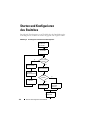
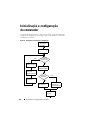
4 Starting and Configuring the Switch
. . .
20
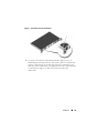
Connecting a Switch to a Terminal
. . . . . . . . . . .
21
Booting the Switch
. . . . . . . . . . . . . . . . . . . .
22
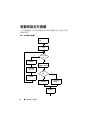
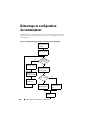
Performing the Initial Configuration
. . . . . . . . . . .
22
Initial Configuration Procedure
. . . . . . . . . . .
23
Example Session
. . . . . . . . . . . . . . . . . .
24
Next Steps
. . . . . . . . . . . . . . . . . . . . .
27

Introduction
5
Introduction
This document provides basic information about the Dell
®
Networking
N4000 Series switches: N4032, N4032F, N4064, N4064F, including how to
install a switch and perform the initial configuration. For information about
how to configure and monitor switch features, see the User’s Configuration
Guide, which is available on the Dell Support website at
dell.com/support for
the latest updates on documentation and firmware.
This document contains the following sections:
• Hardware Overview
• Installation
• Starting and Configuring the Switch
Features
The Dell Networking N4000 Series are highly scalable, non-stop networking
switches for campus aggregation and core switching 10 GbE deployments.
The family of Layer 3 switches delivers 10/40 GbE wire-speed performance
required to power demanding Enterprise and business infrastructures, while
enabling scalability and high density 10 GbE operation with simplified
management.
The N4000 Series delivers high availability and redundancy for small core and
aggregation deployments that helps grow your network to high density 10
GbE operation and to 40 GbE for the Enterprise core. The family delivers
high density stacking with either 10GbE or 40GbE ports, manageable as a
single logical unit, as well as redundancy with power supplies, fans and
firmware images. Simplified management also includes a USB Rapid
Deployment feature to expedite network addressing at bootup, as well as
streamline firmware image installs across the entire stack. Flexible
management options include an industry-standard CLI, remote management
using the embedded web server, and support for SNMP-based management
applications including Dell OpenManage™ Network Manager.

6
Hardware Overview
The N4000 Series includes storage networking support and iSCSI
optimization. To simplify connectivity with Dell EqualLogic arrays, the iSCSI
Auto-Configuration feature in all N4000 Series switches automatically
detects the arrays and configures the switch for optimal throughput. This
feature is enabled by default, streamlining the process to just connecting a
cable. Connectivity with Dell Compellent arrays is also simplified with a
single command configuration.
Dell designed the N4000 Series for energy savings from the power cord to the
ports, starting with EEE-capable ports to reduce active and passive port
power consumption for all ports. In addition to redundant power supplies
that can operate efficiently in all modes, variable speed fans reduce
consumption by adjusting their speed for their environment through multiple
temperature monitors. Lastly, the N4000 Series includes Dell’s Lifetime
Limited Warranty with Basic Hardware Service (repair or replacement) for
life.
Hardware Overview
This section contains information about device characteristics and modular
hardware configurations for the Dell Networking N4000 switches.
Dell Networking N4000 has the following physical dimensions:
• 440 x 460 x 44 mm (W x D x H).
• 17.32 x 18.11 x 1.73 inches (W x D x H).
Dell Networking N4000 has a chassis design with four kinds of solutions and
640 Gbps and 320 Gbps switching bandwidth as listed below:
1
N4032F - 24 port SFP+ 10G + 40G/80G module
2
N4064F - 48 port SFP+ 10G + 2port 40G QSFP + 40G/80G module
3
N4032 - 24 port 10GBaseT + 40G/80G module
4
N4064 - 48 port 10GBaseT + 2port 40G QSFP + 40G/80G module
The module slots can plug in three kinds of modules:
•SFP+
• 10G Base-T
•QSFP+
The system also provides one RS-232 interface RJ45 type console port and a
dedicated Ethernet service port for OOB management functions.

Hardware Overview
7
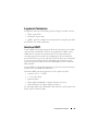
The N4000 has the following features:
• Support one USB port
• Forty-eight 10 Gbps ports for 1G/10G transceiver
• Two fixed 40 Gbps QSFP ports for 40G transceiver
• One 80 Gbps expansion slots for SFP+, 10G Base-T and QSFP+ modules
• On board high performance CPU system with large memory.
XLP308H/256 MB NOR Flash/2GB DDR III RAM.
• Temperature monitoring
• Software readable thermal monitor
• RTC time clock support
• Hot plugging redundant power supply
• Current monitoring for Power management
• The fan is removable and can be managed
• Standard 1U chassis high
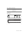
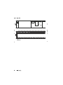
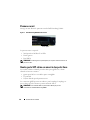
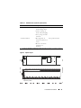
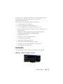
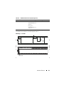
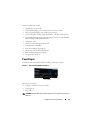
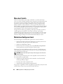
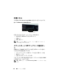
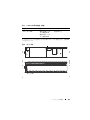
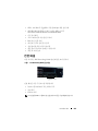
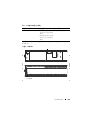
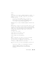
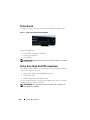
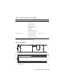
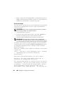
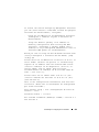
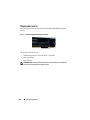
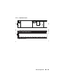
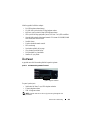
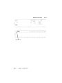
Front Panel
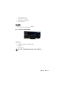
The following image shows the Dell Networking N4000 front panel:
Figure 1. Dell Networking N4000 Front Panel
The front panel includes:
• 24/48 fixed 10G Base-T or SFP+ ports
• Management port
• USB 2.0 port
NOTE:
LED display for System, fan and power status indicators are on the back
panel.
QSFP+ Ports

8
Hardware Overview
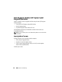
Quad-Port SFP Uplink Fixed Ports
The N4064 and N4064F models feature two fixed QSFP ports, each providing
the following features:
• Four 10G ports with quad-breakout/QBO cable
• One 40G port
• Front panel port status LEDs
The QSFP connections can be used for stacking. Stacking is supported at
distances of up to 100M.
NOTE:
The QSFP modules can be used only for the Dell Networking N4000-series
switches.
Expansion Slot
The 80 Gbps expansion slot supports the following modules:
• SFP+ (four 10G ports)
• 10G Base-T (four 10G ports)
• QSFP+ (may be configured as two 40G ports or up to 8 10G ports)
The modules are sold separately.

Hardware Overview
9
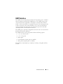
UART Interface
The UART (Universal Asynchronous Receiver Transmitter) port is modeled
after the industry standard 16550 UART devices. The UART port provides
serial communication capabilities, which allows communication with the
model or other external devices using RS-232 protocol. A serial port provides
a direct connection to the switch and allows you to access the CLI from a
console terminal connected to the port through the provided serial cable
(with RJ45 YOST to female DB-9 connectors).
The UART port is separately configurable and can be run as an asynchronous
link from 1200 baud to 4M baud.
The UART interface can be programmed with the following options:
• 5, 6, 7, or 8 character bits
• 1, 1.5, or 2 stop bits
• Parity option
• Even/odd parity (if parity option is enabled)
• Sticky parity (if parity option is enabled)
The defaults are 9600 baud rate, 8 data bits, No Parity, 1 Stop Bit, No Flow
Control.

10
Hardware Overview
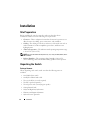
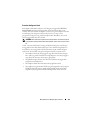
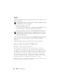
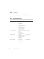
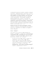
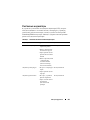
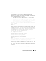
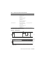
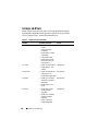
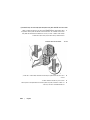
System LEDs
The system contains light emitting diodes (LEDs) that provide indications
about the System, Temp, Diag, Fan, Stack, and Locator status of the Dell
Networking N4000 switch.
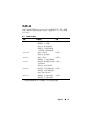
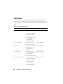
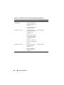
Table 1 contains the status LED definitions:
Table 1. LED Definitions for System
Feature Detailed Description Comment
System LED
• Solid blue - Normal
operation
• Blinking blue - Booting
• Solid red - Critical
system error
• Blinking red - Non-
critical system error (fan
fail, power supply fail)
On front panel
Temp LED
•Off - Normal
temperature
• Solid red - Overtemp
1
On back panel
Diag LED
• Off - Normal operating
• Blinking green -
Diagnostic test running
On back panel
Fan LED
• Solid green - Fan
powered and at expected
RPM
• Solid red - Fan failed
On back panel
Stack LED
• Solid blue - Switch in
stacking master mode
• Solid green - Switch in
stacking slave mode
• Off - Switch in stand
alone mode
On back panel

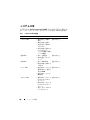
Hardware Overview
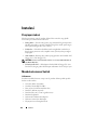
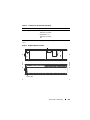
11
Figure 2. Port LEDs
Locator LED
• Blinking blue - Locator
function is enabled
• Solid blue - Locator
function is disabled
On back panel
1. The thermal sensors system temperature threshold is 75°C. When the threshold is exceeded, the
Temp LED lights up to Red.
Table 1. LED Definitions for System (Continued)
Feature Detailed Description Comment
9
10
11
12
15
16
1
2
17
18
13
14
7
8
5
6
PowerConnect 8164
1
2
1
2
1
2
1
2
9
10
11
12
23
24
15
16
21
22
2319
20
17
18
13
14
7
8
5
6
3
4
Console
Locator
FAN 1
Temp
Dlag
Stack
OOB
System LED

12
Installation
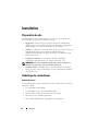
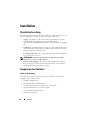
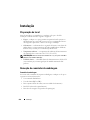
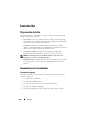
Installation
Site Preparation
Before installing the switch or switches, make sure that the chosen
installation location meets the following site requirements:
•
Clearance
—There is adequate front and rear clearance for operator access.
Allow clearance for cabling, power connections, and ventilation.
•
Cabling
—The cabling is routed to avoid sources of electrical noise such as
radio transmitters, broadcast amplifiers, power lines, and fluorescent
lighting fixtures.
•
Ambient Temperature
—The ambient switch operating temperature range
is 10° to 35ºC (50° to 95ºF).
NOTE:
Decrease the maximum temperature by 1°C (1.8°F) per 300 m (985 ft.) above
900 m (2955 ft.).
•
Relative Humidity
—The operating relative humidity is 8% to 85%
(noncondensing) with a maximum humidity gradation of 10% per hour.
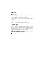
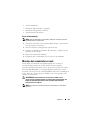
Unpacking the Switch
Package Contents
When unpacking each switch, make sure that the following items are
included:
• One N4000 Series switch
• One RJ45-to-DB-9 female cable
• Two sets of rail kits (no tools required)
• Two PSUs (packed separately)
• Two AC power cords (country/region specific)
• Getting Started Guide
• Safety and Regulatory Information
• Warranty and Support Information
• Software License Agreement

Installation
13
Unpacking Steps
NOTE:
Before unpacking the switch, inspect the container and immediately report
any evidence of damage.
1
Place the container on a clean, flat surface and cut all straps securing the
container.
2
Open the container or remove the container top.
3
Carefully remove the switch from the container and place it on a secure
and clean surface.
4
Remove all packing material.
5
Inspect the product and accessories for damage.
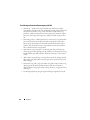
Rack Mounting the Switch
You may either place the switch on the rack shelf or mount the switch directly
into a 19" wide, EIA-310-E compliant rack (four-post, two-post, or threaded
methods). The Dell ReadyRails™ system is provided for 1U front-rack, and
two-post installations. The ReadyRails system includes two separately
packaged rail assemblies and two rails that are shipped attached to the sides
of the switch.
WARNING:
This is a condensed reference. Read the safety instructions in your
Safety, Environmental, and Regulatory information booklet before you begin.
NOTE:
The illustrations in this document are not intended to represent a specific
switch.

14
Installation
Rack Mounting Safety Considerations
• Rack loading—Overloading or uneven loading of racks may result in shelf
or rack failure, causing damage to equipment and possible personal injury.
Stabilize racks in a permanent location before loading begins. Mount
components beginning at the bottom of the rack, then work to the top. Do
not exceed your rack load rating.
• Power considerations—Connect only to the power source specified on the
unit. When multiple electrical components are installed in a rack, ensure
that the total component power ratings do not exceed circuit capabilities.
Overloaded power sources and extension cords present fire and shock
hazards.
• Elevated ambient temperature—If installed in a closed rack assembly, the
operating temperature of the rack environment may be greater than room
ambient. Use care not to exceed the 50 degrees C maximum ambient
temperature of the switch.
• Reduced air flow—Install the equipment in the rack so that the amount of
airflow required for safe operation of the equipment is not compromised.
• Reliable earthing—Maintain reliable earthing of rack-mounted
equipment. Pay particular attention to supply connections other than
direct connections to the branch circuit, for example: use of power strips.
• Product should not be mounted with the rear panel facing in the
downward position.

Installation
15
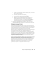
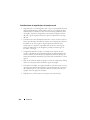
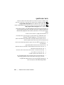
Installing the Dell ReadyRails System
The ReadyRails rack mounting system is provided to easily configure your
rack for installation of your switch. The ReadyRails system can be installed
using the 1U tool-less method or one of three possible 1U tooled methods
(two-post flush mount, two-post center mount, or four-post threaded).
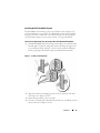
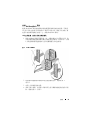
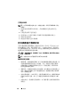
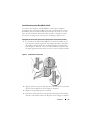
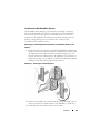
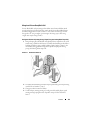
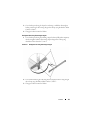
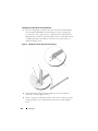
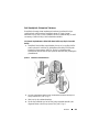
1U Tool-less Configuration (Four-post Square Hole or Unthreaded Round Hole)
1
With the ReadyRails flange ears facing outward, place one rail between the
left and right vertical posts. Align and seat the rear flange rail pegs in the
rear vertical post flange. In
Figure 3, item 1 and its extractions illustrate
how the pegs appear in both the square and unthreaded round holes.
Figure 3. 1U Tool-less Configuration
2
Align and seat the front flange pegs in the holes on the front side of the
vertical post. See
Figure 3, item 2.
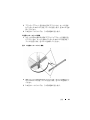
3
Repeat this procedure for the second rail.
4
To remove each rail, pull on the latch release button on each flange ear and
unseat each rail. See
Figure 3, item 3.

16
Installation
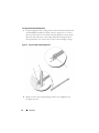
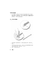
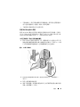
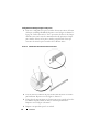
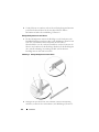
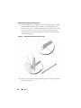
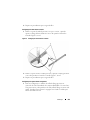
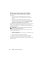
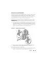
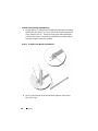
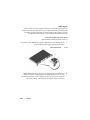
Two-post Flush-mount Configuration
1
For this configuration, the castings must be removed from the front side of
each ReadyRails assembly. See
Figure 4, item 1 on page 16. Use a Torx™
driver to remove the two screws from each front flange ear (on the switch
side of the rail) and remove each casting. Retain the castings for future
rack requirements. It is not necessary to remove the rear flange castings.
Figure 4. Two-post Flush-mount Configuration
2
Attach one rail to the front post flange with two user-supplied screws.
See Figure 4, item 2.

Installation
17
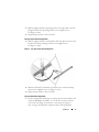
3
Slide the plunger bracket forward against the vertical post and secure the
plunger bracket to the post flange with two user-supplied screws.
See Figure 4, item 3.
4
Repeat this procedure for the second rail.
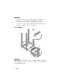
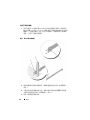
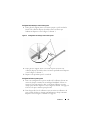
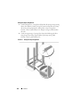
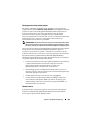
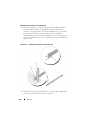
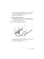
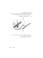
Two-post Center-mount Configuration
1
Slide the plunger bracket rearward until it clicks into place and secure the
bracket to the front post flange with two user-supplied screws.
See Figure 5, item 1.
Figure 5. Two-post Center-mount Configuration
2
Slide the back bracket towards the post and secure it to the post flange
with two user-supplied screws. See
Figure 5, item 2.
3
Repeat this procedure for the second rail.
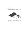
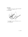
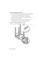
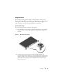
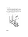
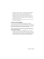
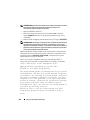
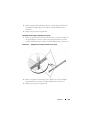
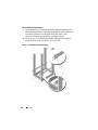
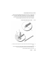
Four-post Threaded Configuration
1
For this configuration, the flange ear castings must be removed from each
end of the ReadyRails assemblies. Use a Torx driver to remove the two
screws from each flange ear and remove each casting. See
Figure 6,
item 1 on page 18. Retain the castings for future rack requirements.

18
Installation
2
For each rail, attach the front and rear flanges to the post flanges with two
user-supplied screws at each end. See
Figure 6, item 2 on page 18.
Figure 6. Four-post Threaded Configuration
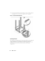
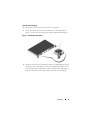
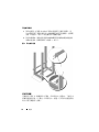
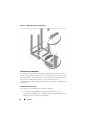
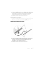
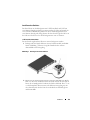
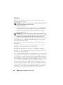
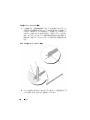
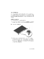
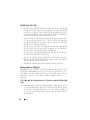
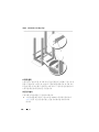
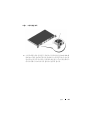
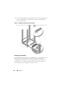
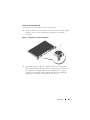
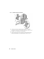
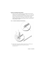
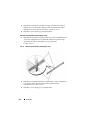
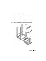
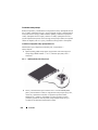
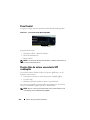
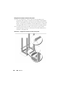
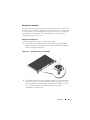
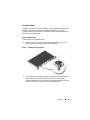
Installing the Switch
The switch may be mounted in the 1U front-rack and 1U two-post (flush and
center) configurations. The following is an example of 1U front-rack
configuration. The 1U two-post (flush and center) configurations, you can
slide the switch into the rails in the same manner as the four-post
configurations.
Sayfa yükleniyor...
Sayfa yükleniyor...
Sayfa yükleniyor...
Sayfa yükleniyor...
Sayfa yükleniyor...
Sayfa yükleniyor...
Sayfa yükleniyor...
Sayfa yükleniyor...
Sayfa yükleniyor...
Sayfa yükleniyor...
Sayfa yükleniyor...
Sayfa yükleniyor...
Sayfa yükleniyor...
Sayfa yükleniyor...
Sayfa yükleniyor...
Sayfa yükleniyor...
Sayfa yükleniyor...
Sayfa yükleniyor...
Sayfa yükleniyor...
Sayfa yükleniyor...
Sayfa yükleniyor...
Sayfa yükleniyor...
Sayfa yükleniyor...
Sayfa yükleniyor...
Sayfa yükleniyor...
Sayfa yükleniyor...
Sayfa yükleniyor...
Sayfa yükleniyor...
Sayfa yükleniyor...
Sayfa yükleniyor...
Sayfa yükleniyor...
Sayfa yükleniyor...
Sayfa yükleniyor...
Sayfa yükleniyor...
Sayfa yükleniyor...
Sayfa yükleniyor...
Sayfa yükleniyor...
Sayfa yükleniyor...
Sayfa yükleniyor...
Sayfa yükleniyor...
Sayfa yükleniyor...
Sayfa yükleniyor...
Sayfa yükleniyor...
Sayfa yükleniyor...
Sayfa yükleniyor...
Sayfa yükleniyor...
Sayfa yükleniyor...
Sayfa yükleniyor...
Sayfa yükleniyor...
Sayfa yükleniyor...
Sayfa yükleniyor...
Sayfa yükleniyor...
Sayfa yükleniyor...
Sayfa yükleniyor...
Sayfa yükleniyor...
Sayfa yükleniyor...
Sayfa yükleniyor...
Sayfa yükleniyor...
Sayfa yükleniyor...
Sayfa yükleniyor...
Sayfa yükleniyor...
Sayfa yükleniyor...
Sayfa yükleniyor...
Sayfa yükleniyor...
Sayfa yükleniyor...
Sayfa yükleniyor...
Sayfa yükleniyor...
Sayfa yükleniyor...
Sayfa yükleniyor...
Sayfa yükleniyor...
Sayfa yükleniyor...
Sayfa yükleniyor...
Sayfa yükleniyor...
Sayfa yükleniyor...
Sayfa yükleniyor...
Sayfa yükleniyor...
Sayfa yükleniyor...
Sayfa yükleniyor...
Sayfa yükleniyor...
Sayfa yükleniyor...
Sayfa yükleniyor...
Sayfa yükleniyor...
Sayfa yükleniyor...
Sayfa yükleniyor...
Sayfa yükleniyor...
Sayfa yükleniyor...
Sayfa yükleniyor...
Sayfa yükleniyor...
Sayfa yükleniyor...
Sayfa yükleniyor...
Sayfa yükleniyor...
Sayfa yükleniyor...
Sayfa yükleniyor...
Sayfa yükleniyor...
Sayfa yükleniyor...
Sayfa yükleniyor...
Sayfa yükleniyor...
Sayfa yükleniyor...
Sayfa yükleniyor...
Sayfa yükleniyor...
Sayfa yükleniyor...
Sayfa yükleniyor...
Sayfa yükleniyor...
Sayfa yükleniyor...
Sayfa yükleniyor...
Sayfa yükleniyor...
Sayfa yükleniyor...
Sayfa yükleniyor...
Sayfa yükleniyor...
Sayfa yükleniyor...
Sayfa yükleniyor...
Sayfa yükleniyor...
Sayfa yükleniyor...
Sayfa yükleniyor...
Sayfa yükleniyor...
Sayfa yükleniyor...
Sayfa yükleniyor...
Sayfa yükleniyor...
Sayfa yükleniyor...
Sayfa yükleniyor...
Sayfa yükleniyor...
Sayfa yükleniyor...
Sayfa yükleniyor...
Sayfa yükleniyor...
Sayfa yükleniyor...
Sayfa yükleniyor...
Sayfa yükleniyor...
Sayfa yükleniyor...
Sayfa yükleniyor...
Sayfa yükleniyor...
Sayfa yükleniyor...
Sayfa yükleniyor...
Sayfa yükleniyor...
Sayfa yükleniyor...
Sayfa yükleniyor...
Sayfa yükleniyor...
Sayfa yükleniyor...
Sayfa yükleniyor...
Sayfa yükleniyor...
Sayfa yükleniyor...
Sayfa yükleniyor...
Sayfa yükleniyor...
Sayfa yükleniyor...
Sayfa yükleniyor...
Sayfa yükleniyor...
Sayfa yükleniyor...
Sayfa yükleniyor...
Sayfa yükleniyor...
Sayfa yükleniyor...
Sayfa yükleniyor...
Sayfa yükleniyor...
Sayfa yükleniyor...
Sayfa yükleniyor...
Sayfa yükleniyor...
Sayfa yükleniyor...
Sayfa yükleniyor...
Sayfa yükleniyor...
Sayfa yükleniyor...
Sayfa yükleniyor...
Sayfa yükleniyor...
Sayfa yükleniyor...
Sayfa yükleniyor...
Sayfa yükleniyor...
Sayfa yükleniyor...
Sayfa yükleniyor...
Sayfa yükleniyor...
Sayfa yükleniyor...
Sayfa yükleniyor...
Sayfa yükleniyor...
Sayfa yükleniyor...
Sayfa yükleniyor...
Sayfa yükleniyor...
Sayfa yükleniyor...
Sayfa yükleniyor...
Sayfa yükleniyor...
Sayfa yükleniyor...
Sayfa yükleniyor...
Sayfa yükleniyor...
Sayfa yükleniyor...
Sayfa yükleniyor...
Sayfa yükleniyor...
Sayfa yükleniyor...
Sayfa yükleniyor...
Sayfa yükleniyor...
Sayfa yükleniyor...
Sayfa yükleniyor...
Sayfa yükleniyor...
Sayfa yükleniyor...
Sayfa yükleniyor...
Sayfa yükleniyor...
Sayfa yükleniyor...
Sayfa yükleniyor...
Sayfa yükleniyor...
Sayfa yükleniyor...
Sayfa yükleniyor...
Sayfa yükleniyor...
Sayfa yükleniyor...
Sayfa yükleniyor...
Sayfa yükleniyor...
Sayfa yükleniyor...
Sayfa yükleniyor...
Sayfa yükleniyor...
Sayfa yükleniyor...
Sayfa yükleniyor...
Sayfa yükleniyor...
Sayfa yükleniyor...
Sayfa yükleniyor...
Sayfa yükleniyor...
Sayfa yükleniyor...
Sayfa yükleniyor...
Sayfa yükleniyor...
Sayfa yükleniyor...
Sayfa yükleniyor...
Sayfa yükleniyor...
Sayfa yükleniyor...
Sayfa yükleniyor...
Sayfa yükleniyor...
Sayfa yükleniyor...
Sayfa yükleniyor...
Sayfa yükleniyor...
Sayfa yükleniyor...
Sayfa yükleniyor...
Sayfa yükleniyor...
Sayfa yükleniyor...
Sayfa yükleniyor...
Sayfa yükleniyor...
Sayfa yükleniyor...
Sayfa yükleniyor...
Sayfa yükleniyor...
Sayfa yükleniyor...
Sayfa yükleniyor...
Sayfa yükleniyor...
Sayfa yükleniyor...
Sayfa yükleniyor...
Sayfa yükleniyor...
Sayfa yükleniyor...
Sayfa yükleniyor...
Sayfa yükleniyor...
Sayfa yükleniyor...
Sayfa yükleniyor...
Sayfa yükleniyor...
Sayfa yükleniyor...
Sayfa yükleniyor...
Sayfa yükleniyor...
Sayfa yükleniyor...
Sayfa yükleniyor...
Sayfa yükleniyor...
Sayfa yükleniyor...
Sayfa yükleniyor...
Sayfa yükleniyor...
Sayfa yükleniyor...
Sayfa yükleniyor...
Sayfa yükleniyor...
Sayfa yükleniyor...
Sayfa yükleniyor...
Sayfa yükleniyor...
Sayfa yükleniyor...
Sayfa yükleniyor...
Sayfa yükleniyor...
Sayfa yükleniyor...
Sayfa yükleniyor...
Sayfa yükleniyor...
Sayfa yükleniyor...
Sayfa yükleniyor...
Sayfa yükleniyor...
Sayfa yükleniyor...
Sayfa yükleniyor...
Sayfa yükleniyor...
Sayfa yükleniyor...
Sayfa yükleniyor...
Sayfa yükleniyor...
Sayfa yükleniyor...
Sayfa yükleniyor...
Sayfa yükleniyor...
Sayfa yükleniyor...
Sayfa yükleniyor...
Sayfa yükleniyor...
Sayfa yükleniyor...
Sayfa yükleniyor...
Sayfa yükleniyor...
Sayfa yükleniyor...
Sayfa yükleniyor...
Sayfa yükleniyor...
Sayfa yükleniyor...
Sayfa yükleniyor...
Sayfa yükleniyor...
Sayfa yükleniyor...
Sayfa yükleniyor...
Sayfa yükleniyor...
Sayfa yükleniyor...
Sayfa yükleniyor...
Sayfa yükleniyor...
Sayfa yükleniyor...
Sayfa yükleniyor...
Sayfa yükleniyor...
Sayfa yükleniyor...
Sayfa yükleniyor...
Sayfa yükleniyor...
Sayfa yükleniyor...
Sayfa yükleniyor...
Sayfa yükleniyor...
Sayfa yükleniyor...
Sayfa yükleniyor...
Sayfa yükleniyor...
Sayfa yükleniyor...
Sayfa yükleniyor...
Sayfa yükleniyor...
Sayfa yükleniyor...
Sayfa yükleniyor...
Sayfa yükleniyor...
Sayfa yükleniyor...
Sayfa yükleniyor...
Sayfa yükleniyor...
Sayfa yükleniyor...
Sayfa yükleniyor...
Sayfa yükleniyor...
Sayfa yükleniyor...
Sayfa yükleniyor...
Sayfa yükleniyor...
Sayfa yükleniyor...
Sayfa yükleniyor...
Sayfa yükleniyor...
Sayfa yükleniyor...
Sayfa yükleniyor...
Sayfa yükleniyor...
Sayfa yükleniyor...
Sayfa yükleniyor...
Sayfa yükleniyor...
Sayfa yükleniyor...
Sayfa yükleniyor...
Sayfa yükleniyor...
Sayfa yükleniyor...
Sayfa yükleniyor...
Sayfa yükleniyor...
Sayfa yükleniyor...
Sayfa yükleniyor...
Sayfa yükleniyor...
Sayfa yükleniyor...
Sayfa yükleniyor...
Sayfa yükleniyor...
Sayfa yükleniyor...
Sayfa yükleniyor...
Sayfa yükleniyor...
Sayfa yükleniyor...
Sayfa yükleniyor...
Sayfa yükleniyor...
Sayfa yükleniyor...
Sayfa yükleniyor...
Sayfa yükleniyor...
Sayfa yükleniyor...
Sayfa yükleniyor...
Sayfa yükleniyor...
Sayfa yükleniyor...
Sayfa yükleniyor...
Sayfa yükleniyor...
Sayfa yükleniyor...
Sayfa yükleniyor...
Sayfa yükleniyor...
-
 1
1
-
 2
2
-
 3
3
-
 4
4
-
 5
5
-
 6
6
-
 7
7
-
 8
8
-
 9
9
-
 10
10
-
 11
11
-
 12
12
-
 13
13
-
 14
14
-
 15
15
-
 16
16
-
 17
17
-
 18
18
-
 19
19
-
 20
20
-
 21
21
-
 22
22
-
 23
23
-
 24
24
-
 25
25
-
 26
26
-
 27
27
-
 28
28
-
 29
29
-
 30
30
-
 31
31
-
 32
32
-
 33
33
-
 34
34
-
 35
35
-
 36
36
-
 37
37
-
 38
38
-
 39
39
-
 40
40
-
 41
41
-
 42
42
-
 43
43
-
 44
44
-
 45
45
-
 46
46
-
 47
47
-
 48
48
-
 49
49
-
 50
50
-
 51
51
-
 52
52
-
 53
53
-
 54
54
-
 55
55
-
 56
56
-
 57
57
-
 58
58
-
 59
59
-
 60
60
-
 61
61
-
 62
62
-
 63
63
-
 64
64
-
 65
65
-
 66
66
-
 67
67
-
 68
68
-
 69
69
-
 70
70
-
 71
71
-
 72
72
-
 73
73
-
 74
74
-
 75
75
-
 76
76
-
 77
77
-
 78
78
-
 79
79
-
 80
80
-
 81
81
-
 82
82
-
 83
83
-
 84
84
-
 85
85
-
 86
86
-
 87
87
-
 88
88
-
 89
89
-
 90
90
-
 91
91
-
 92
92
-
 93
93
-
 94
94
-
 95
95
-
 96
96
-
 97
97
-
 98
98
-
 99
99
-
 100
100
-
 101
101
-
 102
102
-
 103
103
-
 104
104
-
 105
105
-
 106
106
-
 107
107
-
 108
108
-
 109
109
-
 110
110
-
 111
111
-
 112
112
-
 113
113
-
 114
114
-
 115
115
-
 116
116
-
 117
117
-
 118
118
-
 119
119
-
 120
120
-
 121
121
-
 122
122
-
 123
123
-
 124
124
-
 125
125
-
 126
126
-
 127
127
-
 128
128
-
 129
129
-
 130
130
-
 131
131
-
 132
132
-
 133
133
-
 134
134
-
 135
135
-
 136
136
-
 137
137
-
 138
138
-
 139
139
-
 140
140
-
 141
141
-
 142
142
-
 143
143
-
 144
144
-
 145
145
-
 146
146
-
 147
147
-
 148
148
-
 149
149
-
 150
150
-
 151
151
-
 152
152
-
 153
153
-
 154
154
-
 155
155
-
 156
156
-
 157
157
-
 158
158
-
 159
159
-
 160
160
-
 161
161
-
 162
162
-
 163
163
-
 164
164
-
 165
165
-
 166
166
-
 167
167
-
 168
168
-
 169
169
-
 170
170
-
 171
171
-
 172
172
-
 173
173
-
 174
174
-
 175
175
-
 176
176
-
 177
177
-
 178
178
-
 179
179
-
 180
180
-
 181
181
-
 182
182
-
 183
183
-
 184
184
-
 185
185
-
 186
186
-
 187
187
-
 188
188
-
 189
189
-
 190
190
-
 191
191
-
 192
192
-
 193
193
-
 194
194
-
 195
195
-
 196
196
-
 197
197
-
 198
198
-
 199
199
-
 200
200
-
 201
201
-
 202
202
-
 203
203
-
 204
204
-
 205
205
-
 206
206
-
 207
207
-
 208
208
-
 209
209
-
 210
210
-
 211
211
-
 212
212
-
 213
213
-
 214
214
-
 215
215
-
 216
216
-
 217
217
-
 218
218
-
 219
219
-
 220
220
-
 221
221
-
 222
222
-
 223
223
-
 224
224
-
 225
225
-
 226
226
-
 227
227
-
 228
228
-
 229
229
-
 230
230
-
 231
231
-
 232
232
-
 233
233
-
 234
234
-
 235
235
-
 236
236
-
 237
237
-
 238
238
-
 239
239
-
 240
240
-
 241
241
-
 242
242
-
 243
243
-
 244
244
-
 245
245
-
 246
246
-
 247
247
-
 248
248
-
 249
249
-
 250
250
-
 251
251
-
 252
252
-
 253
253
-
 254
254
-
 255
255
-
 256
256
-
 257
257
-
 258
258
-
 259
259
-
 260
260
-
 261
261
-
 262
262
-
 263
263
-
 264
264
-
 265
265
-
 266
266
-
 267
267
-
 268
268
-
 269
269
-
 270
270
-
 271
271
-
 272
272
-
 273
273
-
 274
274
-
 275
275
-
 276
276
-
 277
277
-
 278
278
-
 279
279
-
 280
280
-
 281
281
-
 282
282
-
 283
283
-
 284
284
-
 285
285
-
 286
286
-
 287
287
-
 288
288
-
 289
289
-
 290
290
-
 291
291
-
 292
292
-
 293
293
-
 294
294
-
 295
295
-
 296
296
-
 297
297
-
 298
298
-
 299
299
-
 300
300
-
 301
301
-
 302
302
-
 303
303
-
 304
304
-
 305
305
-
 306
306
-
 307
307
-
 308
308
-
 309
309
-
 310
310
-
 311
311
-
 312
312
-
 313
313
-
 314
314
-
 315
315
-
 316
316
-
 317
317
-
 318
318
-
 319
319
-
 320
320
-
 321
321
-
 322
322
-
 323
323
-
 324
324
-
 325
325
-
 326
326
-
 327
327
-
 328
328
-
 329
329
-
 330
330
-
 331
331
-
 332
332
-
 333
333
-
 334
334
-
 335
335
-
 336
336
-
 337
337
-
 338
338
-
 339
339
-
 340
340
-
 341
341
-
 342
342
-
 343
343
-
 344
344
-
 345
345
-
 346
346
-
 347
347
-
 348
348
-
 349
349
-
 350
350
-
 351
351
-
 352
352
-
 353
353
-
 354
354
-
 355
355
-
 356
356
-
 357
357
-
 358
358
-
 359
359
-
 360
360
-
 361
361
-
 362
362
-
 363
363
-
 364
364
-
 365
365
-
 366
366
-
 367
367
-
 368
368
-
 369
369
-
 370
370
-
 371
371
-
 372
372
-
 373
373
-
 374
374
-
 375
375
-
 376
376
-
 377
377
-
 378
378


Dell PowerSwitch N4000 Series Hızlı başlangıç Kılavuzu
- Kategori
- Ağ oluşturma
- Tip
- Hızlı başlangıç Kılavuzu