Miele PDR 914 HP Installation Plan
- Tip
- Installation Plan

PDR914HP
en Installation plan Commercial heat-pump dryer
pt Plano de instalação Secador industrial com bomba de calor
pl Plan instalacyjny Profesjonalna suszarka zpompą ciepła
cs Instalační plán Profesionální sušička stepelným čerpadlem
hu Szerelési terv Ipari hőszivattyús szárítógép
tr Kurulum planı Sanayi Tipi Isı Pompalı Kurutma Makinesi
M.-Nr. 11 969 420

2
en ...................................................................................................................................... 4
pt ....................................................................................................................................... 14
pl ....................................................................................................................................... 24
cs ....................................................................................................................................... 34
hu ...................................................................................................................................... 44
tr ........................................................................................................................................ 54

en - Contents
3
Installation notes............................................................................................................. 4
Installation requirements ................................................................................................... 4
Electrical connection......................................................................................................... 4
Peak-load negotiation ....................................................................................................... 5
Air intake vent.................................................................................................................... 5
Air outlet vent .................................................................................................................... 6
Condensate drainage ........................................................................................................ 6
PDR914 with heat pump ................................................................................................ 7
Dimensions........................................................................................................................ 7
Installation ......................................................................................................................... 8
Installation (standard) ........................................................................................................ 9
Installation (concrete plinth) .............................................................................................. 10
Technical data.................................................................................................................. 11
Possible voltage variants................................................................................................... 11
Peak-load negotiation (optional)........................................................................................ 11
Condensate drainage ........................................................................................................ 11
Machine data..................................................................................................................... 11
Fixing options.................................................................................................................... 12
Fixing without plinth ...................................................................................................... 12
Fixing to concrete plinth................................................................................................ 12
Options/Accessories ......................................................................................................... 12
Concrete base (on site) ................................................................................................. 12

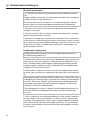
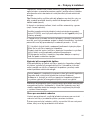
en - Installation notes
4
Installation requirements
Risk of injury or damage to property due to improper installa-
tion.
Incorrect installation of the tumble dryer can lead to personal injury
or damage to property.
The tumble dryer must only be installed and commissioned by
Miele Customer Service Department or an authorised dealer.
The tumble dryer must be installed in accordance with all relevant
regulations and standards.
The dryer must only be operated in a room that has sufficient vent-
ilation and which is frost-free.
The tumble dryer must not be installed behind a closeable door or
a sliding door. The maximum opening angle of the tumble dryer door
must not be limited by objects or doors. It must be possible to fully
open the tumble dryer door at any time.
Electrical connection
The electrical connection must be established by a qualified electri-
cian.
The electrical connection may only be made to an electrical system
provided in accordance with all appropriate local and national legisla-
tion, regulations and guidelines. Please also observe the regulations
set out by your insurance provider and energy supplier, accident pre-
vention regulations, as well as recognised codes of practice.
Reliable and safe operation of this tumble dryer is only ensured if it
has been connected to the mains electricity supply.
The required supply voltage, power rating and fuse rating can be
found on the data plate on the tumble dryer. Ensure that the supply
voltage matches the voltage quoted on the data plate before estab-
lishing the electrical connection to the tumble dryer.
Connection to a supply voltage other than the one quoted on the
data plate can damage the tumble dryer if the voltage is too high.
If more than one voltage is specified on the data plate, the tumble
dryer can be converted for connection to the relevant input voltage.
This conversion must be performed by the Miele Customer Service
Department or by an authorised dealer. During the conversion, the
wiring instructions given on the wiring diagram must be followed.
Tip: We recommend connecting the tumble dryer to the power supply
via a plug and socket so that it is easier to conduct electrical safety
checks (e.g. during maintenance or repair work).

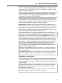
en - Installation notes
5
It is advisable to connect the product via a suitably rated plug and
socket in accordance with IEC-60309, otherwise for a hardwired con-
nection an all pole means of isolation must be installed at the site.
An isolation device is a switch which ensures a contact opening of
more than 3mm. These include circuit breakers, fuses and contact-
ors (IEC/EN60947).
If the mains supply cannot be permanently disconnected, the isola-
tion device (including plug and socket) must be safeguarded against
being switched on either unintentionally or without authorisation.
The tumble dryer must not be connected to devices such as timers
which would switch it off automatically.
If local regulations require that a residual current device (RCD) is in-
stalled, a typeB residual current device (sensitive to universal cur-
rent) must be used.
If local and national installation specifications require equipotential
bonding, good galvanic contact must be guaranteed. Equipotential
bonding must have an earth current rating >10mA.
Loud noises and risk of damage due to incorrect phase connec-
tion on heat-pump dryers.
An incorrect phase position causes a lot of noise in tumble dryers
with heat pumps and can cause damage to the compressor.
When connecting a heat-pump dryer to the power connection, en-
sure the correct phase position according to the wiring diagram.
Peak-load negotiation
The heat-pump dyer can be connected to peak-load negotiation if
this is required. However, this is not essential, as the heat-pump dryer
has been designed for very low energy consumption.
Depending on the function, switching off the appliance externally
during the drying process when the heat-pump is in use can re-
duce the service life of the appliance.
Please note that if it is connected to peak-load negotiation, the
heat-pump dryer must not be switched off.
Information on operating status is made available via the
Mielepeak-load interface. Please note that the energy requirement
of all appliances that cannot be switched off in the energy manage-
ment system must be stored by the control system.
Air intake vent
The air supply for the cooler is drawn in through the air intake vent
on the front of the machine directly from the room in which the dryer
is installed.

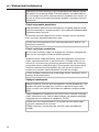
en - Installation notes
6
There is a fluff filter in the dryer’s air intake vent which must be de-
fluffed regularly by hand.
The air intake vent must always be kept clear. It must not be
covered.
Air outlet vent
Separate vent ducting is not required for the heat pump dryer due to
the closed air circuit.
The hot air that is blown out from the heat exchanger to cool it warms
the room air. Therefore, ensure sufficient room ventilation, e.g. by
means of ventilation openings that cannot be closed. If the room is
not sufficiently ventilated, the drying time will be longer, which will
also increase the energy requirement of the dryer.
The air outlet vent must never be closed or covered by objects.
Condensate drainage
The heat pump in this tumble dryer operates according to the prin-
ciple of condensation. A separate floor drain must be provided in the
installation room for condensate produced during the drying pro-
cess.
The condensate drainage point is located at the back of the heat-
pump dryer. The condensate must be drained to the floor drain via a
DN30 pipe pointing downwards.
It must be ensured that condensate cannot flow back into the
dryer.
Any condensate that gets back into the machine can cause dam-
age.

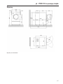
en - PDR914 with heat pump
7
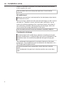
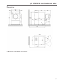
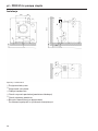
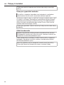
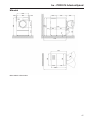
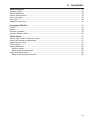
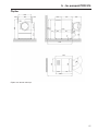
Dimensions
906
403
>20
Ø 520
650
1400
900 642
1240
50
752
1400
20
595 Ø 630
1700
45°
>20
1240
747
1700
906
900
< 180°
38
1370
403 747
403
Dimensions quoted in millimetres

en - PDR914 with heat pump
8
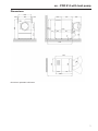
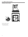
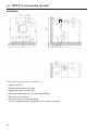
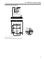
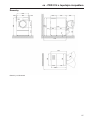
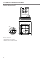
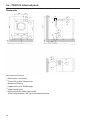
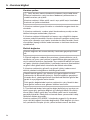
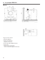
Installation
620
82
1342
1600
95
4
4
50
5
82
~485
1
1
1600
5
3
1
2
3
280
450 450
2
3
2
6
96
Dimensions quoted in millimetres
aElectrical connection
bPeak-load negotiation
cCondensate drainage
dAir intake vent (cool air)
eAir outlet vent
fCommunication box (optional)
For setting up a connection with external systems

en - PDR914 with heat pump
9
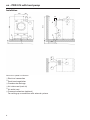
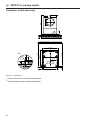
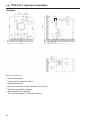
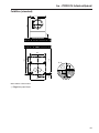
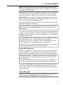
Installation (standard)
1700
20
1400
926
900
A
747 403
463
~48
10
~55
1597
103
A
A-A
77
7
Dimensions quoted in millimetres
fDrill hole/anchor point

en - PDR914 with heat pump
10
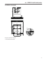
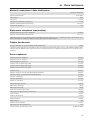
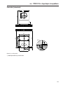
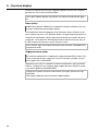
Installation (concrete plinth)
1700
20
1400
10
>1050
B
>50
1597
463
~48
>62
~55
>1200
103
B
B-B
7
77
>62
>50
926
8
Dimensions quoted in millimetres
fDrill hole/anchor point
gConcrete base (on site)

en - Technical data
11
Possible voltage variants
Standard connection
Supply voltage 3N AC 400V
Frequency 50Hz
Power rating 4.9kW
Fuse rating (on site) 3×16A
Minimum cross-section for connection cable 5×2.5mm²
Cable gland M25
Peak-load negotiation (optional)
Supply voltage for control contacts AC 230V
Minimum cross-section for connection cable 5×1,5mm²
Miele recommends using a flexible connection cable with an additional isolation option to establish the connection. The isolator should
remain visible once the tumble dryer has been installed and must be freely accessible.
Condensate drainage
Condensate connector on machine side (external diameter) 30mm
The tumble dryer with heat pump operates according to the principle of condensation. The condensate that accumulates must be
drained away separately via a floor drain. The water can be routed to the floor drain via a hose or pipe pointing downwards.
Machine data
Machine width, total 906mm
Machine height, total 1400mm
Machine depth, total 1232mm
Net width of heat pump module 912mm
Net height of heat pump module 1400mm
Net depth of heat pump module 426mm
Niche width 1250mm
Recommended wall spacing (up to the front edge of the machine) 1700mm
Minimum wall spacing (up to the back edge of the lid) 500mm
Packaging width 1090mm
Packaging height 1526mm
Packaging depth 1738mm
Maximum gross volume 2890.9l
Maximum gross weight 167.7kg
Maximum net weight 156.4kg
Net weight of heat pump module 168.4kg
Max. floor load in operation 1740N
Drum diameter 850mm
Diameter of drum opening 520mm
Drum depth 480mm
Drum volume 250l
Diameter of door opening 520mm
Maximum door opening angle 180°
Emission sound pressure level 51 dB(A) re 20 µPa

en - Technical data
12
Sound power level 62
Average heat dissipation rate into the room 3.9MJ/h
Permissible ambient temperature range 10–40°C
Fixing options
Fixing without plinth
Quantity Screw size
Tensioning strips 2
Wood screws DIN571 (Ø×length) 2 6×40mm
Plugs (Ø×length) 2 10×50mm
If the tumble dryer is being installed without a plinth, fixing it in place is recommended.
Fastenings for floating screed must be supplied by the customer on site.
Fixing to concrete plinth
Quantity Screw size
Tensioning strips 2
Wood screws DIN571 (Ø×length) 2 6×40mm
Plugs (Ø×length) 2 10×50mm
If the tumble dryer is being fixed to a concrete plinth on site, fixing in place is absolutely essential.
Fastenings for floating screed must be supplied by the customer on site.
Options/Accessories
Concrete base (on site)
Minimum width 1050mm
Recommended height 100mm
Minimum height 50mm
Minimum depth 1200mm
The quality of the concrete and its strength must be assessed according to the machine load. The on-site concrete plinth must be fixed
adequately to the floor.

pt - Índice
13
Indicações de instalação................................................................................................ 14
Pré-requisitos de instalação.............................................................................................. 14
Ligação elétrica ................................................................................................................. 14
Corte de pico de carga...................................................................................................... 15
Abertura de entrada de ar ................................................................................................. 16
Abertura de saída de ar..................................................................................................... 16
Esgoto da água condensada ............................................................................................ 16
PDR914 com bomba de calor ....................................................................................... 17
Dimensões......................................................................................................................... 17
Instalação .......................................................................................................................... 18
Montagem (padrão)........................................................................................................... 19
Montagem (base de betão) ............................................................................................... 20
Dados técnicos................................................................................................................ 21
Variantes de tensão e caraterísticas elétricas ................................................................... 21
Desativação de picos de carga (opcional) ........................................................................ 21
Esgoto da água condensada ............................................................................................ 21
Dados do aparelho............................................................................................................ 21
Variantes de fixação .......................................................................................................... 22
Fixação sem sapata ...................................................................................................... 22
Fixação à base de betão............................................................................................... 22
Opções/Acessórios........................................................................................................... 22
Base de betão (no local de instalação) ......................................................................... 22

pt - Indicações de instalação
14
Pré-requisitos de instalação
Ferimentos em pessoas ou danos materiais devido a uma ins-
talação incorreta.
A instalação incorreta do secador pode causar ferimentos em pes-
soas ou danos materiais.
A instalação e a colocação em funcionamento do secador só po-
dem ser executadas pelo serviço de assistência técnica da Miele
ou por um distribuidor autorizado.
O secador deve ser instalado de acordo com as normas e regula-
mentos em vigor.
Opere o secador somente em locais bem ventilados e sem risco
de ocorrência de gelo.
O secador não pode ser colocado atrás de uma porta com fecho
ou de uma porta deslizante. O ângulo máximo de abertura da porta
do secador não pode ser limitado por objetos ou portas. Tem de ser
possível abrir completamente e sem restrições a porta do secador a
qualquer momento.
Ligação elétrica
A ligação elétrica deve ser efetuada por um eletricista qualificado.
A ligação elétrica deve ser efetuada apenas a uma instalação elé-
trica concebida de acordo com as leis, portarias e diretivas nacio-
nais, assim como com as regras e regulamentos locais. Além disso,
devem ser tidos em conta os regulamentos das empresas fornecedo-
ras de eletricidade e seguradoras, os regulamentos de prevenção de
acidentes e os regulamentos técnicos reconhecidos.
O funcionamento fiável e seguro do secador está garantido apenas
se o aparelho estiver ligado à rede pública de eletricidade.
A tensão de alimentação elétrica necessária, o consumo de ener-
gia e os requisitos para a proteção por disjuntor estão indicados na
placa de caraterísticas do secador. Certifique-se de que a tensão
de alimentação corresponde à tensão indicada na placa de carate-
rísticas, antes de efetuar a ligação elétrica!
Com valores de tensão diferentes, existe o perigo de o secador fi-
car danificado devido a uma tensão de alimentação elétrica muito
elevada.
Se na placa de caraterísticas estiverem indicados vários valores de
tensão, então o secador pode ser convertido para a ligação à respeti-
va tensão de entrada. Esta conversão só pode ser efetuada pelo ser-
viço de assistência técnica da Miele ou por distribuidores autoriza-
dos. Para a conversão, devem ser observadas as indicações de colo-
cação de novos fios no esquema elétrico.

pt - Indicações de instalação
15
O secador pode ser ligado através de uma ligação fixa ou através de
um conector de acordo com a norma IEC60309-1. Para uma ligação
fixa, deve estar disponível no local de instalação um dispositivo de
separação da rede de todos os polos.
Como dispositivo de separação da rede são válidos os interruptores
que têm uma abertura de contacto com mais de 3mm. Estes in-
cluem, p.ex., disjuntores, fusíveis e contactores (IEC/EN60947).
O dispositivo de separação da rede (incluindo conector) deve estar
protegido contra ligação involuntária e não autorizada se uma inter-
rupção permanente de eletricidade não poder ser controlada a partir
de qualquer ponto de acesso.
Dica: De preferência, a ligação do secador à corrente deve ser feita
através de conectores, para que as verificações de segurança elétrica
possam ser realizadas facilmente (p.ex., durante uma manutenção
ou reparação).
Não é permitida a instalação de dispositivos que desliguem o se-
cador automaticamente (p.ex., temporizadores).
Se, de acordo com os requisitos locais, for necessário instalar um
disjuntor diferencial residual (RCD), tem de ser obrigatoriamente
utilizado um disjuntor diferencial residual tipoB (universal).
Quando as disposições de instalação locais e nacionais exigirem
uma ligação equipotencial, tem de ser estabelecida uma ligação
equipotencial com bom contacto. A ligação equipotencial deve ser
executada com uma corrente de fuga >10mA.
Forte formação de ruído e perigo de danos devido a uma liga-
ção errada das fases em secadores com bomba de calor.
Uma posição errada das fases em secadores com bomba de calor
provoca uma forte formação de ruído, podendo levar à danificação
do compressor.
Na ligação à rede de um secador com bomba de calor, assegure a
posição correta das fases de acordo com o esquema elétrico.
Corte de pico de carga
Se necessário, o secador com bomba de calor pode ser ligado a uma
ligação de corte de pico de carga. No entanto, isto geralmente não
será necessário, já que o secador com bomba de calor se carateriza
por um consumo de energia muito baixo.
Funcionalmente, desligar externamente durante o processo de se-
cagem com utilização da bomba de calor leva a uma redução da
vida útil.
Observe que, com uma ligação um corte de picos de carga, o se-
cador com bomba de calor não deve ser desligado.

pt - Indicações de instalação
16
As informações sobre o estado de funcionamento são fornecidas
através da interface de picos de carga daMiele. Observe que a ne-
cessidade de energia de todos os aparelhos que não podem ser
desligados deve ser guardada no sistema de gestão de energia atra-
vés da tecnologia de comando.
Abertura de entrada de ar
A alimentação de ar para o dessuperaquecedor é efetuada através
da abertura de entrada de ar frontal do secador e é extraída direta-
mente do local de instalação.
Na abertura da entrada de ar do secador está um filtro de cotão, que
deve ser limpo à mão regularmente.
A abertura da entrada de ar deve estar sempre livre e não pode ser
tapada.
Abertura de saída de ar
Não é necessário um tubo de saída de ar separado para o secador
com bomba de calor devido ao circuito de ar fechado.
O ar quente soprado para arrefecimento de ar do permutador de ca-
lor aquece o ar ambiente. Por conseguinte, assegure um arejamento
suficiente do local, p. ex., através de orifícios de arejamento que não
possam ser fechados. No caso de um arejamento insuficiente do lo-
cal, o tempo de secagem é prolongado, o que também aumenta a
necessidade de energia do secador.
A abertura de saída de ar nunca deve ser fechada ou coberta por
objetos.
Esgoto da água condensada
A bomba de calor deste secador funciona de acordo com o princí-
pio de condensação. Para a água condensada acumulada pelo se-
cador deve ser instalado no local de instalação um ralo no chão se-
parado.
O escoamento da água condensada encontra-se na zona posterior
do secador com bomba de calor. A condensação deve ser conduzida
até ao ralo no chão através de um tubo (DN30) com inclinação.
Deve certificar-se de que a água condensada não pode voltar para
o secador.
O retorno da água condensada pode causar danos.

pt - PDR914 com bomba de calor
17
Dimensões
906
403
>20
Ø 520
650
1400
900 642
1240
50
752
1400
20
595 Ø 630
1700
45°
>20
1240
747
1700
906
900
< 180°
38
1370
403 747
403
As dimensões estão indicadas em milímetros

pt - PDR914 com bomba de calor
18
Instalação
620
82
1342
1600
95
4
4
50
5
82
~485
1
1
1600
5
3
1
2
3
280
450 450
2
3
2
6
96
As dimensões estão indicadas em milímetros
aLigação elétrica
bDesativação de pico de carga
cEsgoto da água condensada
dAbertura da entrada de ar (ar de arrefecimento)
eAbertura de saída de ar
fCaixa de comunicação (opcional)
Para o estabelecimento de ligação com sistemas externos

pt - PDR914 com bomba de calor
19
Montagem (padrão)
1700
20
1400
926
900
A
747 403
463
~48
10
~55
1597
103
A
A-A
77
7
As dimensões estão indicadas em milímetros
gPonto de fixação/orifício

pt - PDR914 com bomba de calor
20
Montagem (base de betão)
1700
20
1400
10
>1050
B
>50
1597
463
~48
>62
~55
>1200
103
B
B-B
7
77
>62
>50
926
8
As dimensões estão indicadas em milímetros
gPonto de fixação/orifício
hBase de betão (no local)
Sayfa yükleniyor ...
Sayfa yükleniyor ...
Sayfa yükleniyor ...
Sayfa yükleniyor ...
Sayfa yükleniyor ...
Sayfa yükleniyor ...
Sayfa yükleniyor ...
Sayfa yükleniyor ...
Sayfa yükleniyor ...
Sayfa yükleniyor ...
Sayfa yükleniyor ...
Sayfa yükleniyor ...
Sayfa yükleniyor ...
Sayfa yükleniyor ...
Sayfa yükleniyor ...
Sayfa yükleniyor ...
Sayfa yükleniyor ...
Sayfa yükleniyor ...
Sayfa yükleniyor ...
Sayfa yükleniyor ...
Sayfa yükleniyor ...
Sayfa yükleniyor ...
Sayfa yükleniyor ...
Sayfa yükleniyor ...
Sayfa yükleniyor ...
Sayfa yükleniyor ...
Sayfa yükleniyor ...
Sayfa yükleniyor ...
Sayfa yükleniyor ...
Sayfa yükleniyor ...
Sayfa yükleniyor ...
Sayfa yükleniyor ...
Sayfa yükleniyor ...
Sayfa yükleniyor ...
Sayfa yükleniyor ...
Sayfa yükleniyor ...
Sayfa yükleniyor ...
Sayfa yükleniyor ...
Sayfa yükleniyor ...
Sayfa yükleniyor ...
Sayfa yükleniyor ...
Sayfa yükleniyor ...
Sayfa yükleniyor ...
Sayfa yükleniyor ...
-
 1
1
-
 2
2
-
 3
3
-
 4
4
-
 5
5
-
 6
6
-
 7
7
-
 8
8
-
 9
9
-
 10
10
-
 11
11
-
 12
12
-
 13
13
-
 14
14
-
 15
15
-
 16
16
-
 17
17
-
 18
18
-
 19
19
-
 20
20
-
 21
21
-
 22
22
-
 23
23
-
 24
24
-
 25
25
-
 26
26
-
 27
27
-
 28
28
-
 29
29
-
 30
30
-
 31
31
-
 32
32
-
 33
33
-
 34
34
-
 35
35
-
 36
36
-
 37
37
-
 38
38
-
 39
39
-
 40
40
-
 41
41
-
 42
42
-
 43
43
-
 44
44
-
 45
45
-
 46
46
-
 47
47
-
 48
48
-
 49
49
-
 50
50
-
 51
51
-
 52
52
-
 53
53
-
 54
54
-
 55
55
-
 56
56
-
 57
57
-
 58
58
-
 59
59
-
 60
60
-
 61
61
-
 62
62
-
 63
63
-
 64
64


Miele PDR 914 HP Installation Plan
- Tip
- Installation Plan
Diğer dillerde
- slovenčina: Miele PDR 914 HP
- polski: Miele PDR 914 HP
- português: Miele PDR 914 HP
İlgili Makaleler
-
Miele PDR 514 COP Installation Plan
-
Miele PDR 918 Installation Plan
-
Miele PDR 522 ROP Installation Plan
-
Miele PDR 518 COP Installation Plan
-
-
Miele PDR 544 ROP Installation Plan
-
Miele PDR 522 TOP Installation Plan
-
-
Miele PDR 510 COP Mounting Plan
-
Miele PDW 909 Installation Plan