Brocade Communications Systems Brocade 6520 Hızlı başlangıç Kılavuzu
- Kategori
- Ağ anahtarları
- Tip
- Hızlı başlangıç Kılavuzu

Brocade 6520 QuickStart Guide
Complete the steps in this guide to install and set up your Brocade 6520 switch in a single-switch configuration using
EZSwitchSetup. See the Brocade 6520 Hardware Reference Manual and the Fabric OS Administrator’s Guide if you want
to choose a different setup.
Ensure that you have the items listed below. Write down the IP network values in the space provided.
Getting ready
Fixed IP address (IPv4 or IPv6) for the switch (no DHCP server): __________________________________________________
Subnet mask value: ______________________________________________________________________________________
Default Gateway value: ___________________________________________________________________________________
Brocade switch World Wide Name (WWN): located on the switch ID pullout: ________________________________________
Ethernet connection (hub or switch) Ethernet and Fibre Channel cables
EZSwitchSetup CD Setup computer
Host computer with an installed HBA Disk array
Standard screw driver Optical SFP+ transceivers
Browser that allows pop-up windows
1
Powering up and connecting cables to the switch
3
Installing and starting EZSwitchSetup
2
1. Insert the EZSwitchSetup CD into the CD-ROM drive of your setup computer. The installer will autostart in about a minute.
2. Follow the EZSwitchSetup directions for installation. Installation will take a few minutes after you click OK.
3. Wait for EZSwitchSetup to start, which should happen automatically after it is installed.
For Windows and Linux instructions, refer to the EZSwitchSetup Administrator’s Guide.
4. On the EZSwitchSetup Introduction screen, choose the option that matches your setup configuration:
• Ethernet connection. This option uses the Ethernet LAN connection you will use for running EZSwitchSetup Manager.
• Direct connection to the switch with a serial cable.
Most users will find it more convenient to use the Ethernet connection.
5. Click Next. The Connect Cables screen is displayed.
4. Click Next.
• If you chose to use the Ethernet connection, the Discover Switch screen is displayed. Enter the switch WWN, following
the instructions on the Discover Switch screen. After completing switch discovery, the Set Switch IP Address screen
is displayed.
• If you chose to use the serial port connection, the Set Switch IP Address screen is immediately displayed.
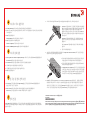
The Connect Cables screen shows you the connections you need to make.
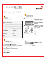
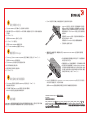
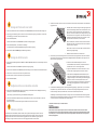
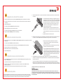
1. Connect the power cord to the switch and to a power
source (1). The power and status LEDs display amber then
green. This can take from one to three minutes.
2. Connect the switch and the setup computer to the
same LAN using Ethernet cables (3, 5) and an Ethernet
hub or switch (2). Be sure the Ethernet hub or switch is
connected to a power source (6).
3. If you want to use a serial connection for setup, connect
your setup computer COM port (7) to the serial port on the
switch using the serial cable shipped with the switch (4).
The serial connection settings are as follows:
• Bits per second: 9600
• Databits: 8
• Parity: none
• Stop bits: 1
• Flow control: none
1
2
7
5
6
4
3

Setting the switch IP address
4
1. Enter the required information on the Set Switch IP Address screen.
2. If prompted to install Active X or a version of the Java runtime environment, do so. Reboot the setup computer, if required.
3. Click Next.
The Confirm IP Address screen is displayed.
4. Click Next to confirm the addresses.
The Continue Configuration screen is displayed.
5. Click Continue with EZManager.
1. Install the SFP+ transceivers in the Fibre Channel ports on the switch to match the ports shown onscreen.
2. Make the physical connections to your host and storage devices. Match the physical connections shown on the
Configure Ports and Connect Devices screen.
3. The Finish screen will display this message: “Congratulations - you’ve successfully completed the setup!” If you used the
serial connection for setup, you can remove the serial cable.
Additional configuration options, such as custom zoning, are available from EZManager. See the EZSwitchSetup
Administrator’s Guide for more information on custom zoning, and other switch configuration and management options.
Setting the switch password
5
1. Click Next on the EZManager Welcome to Switch Configuration screen.
The Set Parameters screen is displayed.
2. Create a new administrator account password in the Set Parameters screen.
3. Enter a new name for the switch (optional step).
4. Adjust the date and time for your time zone (optional step).
5. Click Next.
Configuring the zones and performing device selection
6
1. Select Typical Zoning on the Select Zoning screen and click Next.
Typical Zoning is the default zone configuration.
2. Enter the number and types of devices that you are connecting to the switch on the Device Selection screen.
EZSwitchSetup uses these values to automatically configure the ports on your switch.
Connecting devices
7
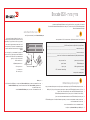
The Connect Devices screen displays a graphical representation of the switch with the device connections based on the
information that you entered when you configured zones and performed device selection. The screen will show all physical
connections as missing until you connect the devices that you specified.
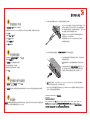
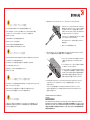
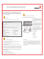
a. The 16 Gbps SFP+ transceivers have a long pull tab and no latching
wire bail. Remove any protector plugs from the SFP+ transceivers you
are going to use, and position and insert each SFP+ transceiver as
required (right side up in the top row of ports and upside down in the
bottom row of ports). Use the pull tab on the 16 Gbps SFP+ tranceivers
to help push the transceiver into the port.
If you are using 16 Gbps SFP+ transceivers, you may want to connect
the cable to the SFP+ first, and then insert them into the port as a unit.
If you are using 8 or 10 Gbps SFP+ transceivers, close the latching wire bail.
b. Repeat for the other ports.
a. Remove plastic protector caps from the Fibre Channel cable ends (if any),
and position the cable connector so that it is oriented correctly.
b. Insert the cable connector into the SFP+ transceiver until it is firmly
seated and the latching mechanism clicks.
c. The Configure Ports and Connect Devices screen shows missing,
valid, and invalid connections as you cable the switch. Note that it
can take up to 15 seconds for the connection to display as a valid
connection. Verify that the connections are all green and click Next.
!
© 2012 Brocade Communications Systems, Inc. All Rights Reserved.
53-1002706-01
*53-1002706-01*
!
Brocade, Brocade Assurance, the B-wing symbol, BigIron, DCX, Fabric OS, FastIron, MLX, NetIron, SAN Health, ServerIron, TurboIron, VCS, and VDX are
registered trademarks, and AnyIO, Brocade One, CloudPlex, Effortless Networking, ICX, NET Health, OpenScript, and The Effortless Network are trademarks
of Brocade Communications Systems, Inc., in the United States and/or in other countries. Other brands, products, or service names mentioned may be
trademarks of their respective owners.

Brocade 6520 快速入门指南
准备工作
交换机的固定 IP 地址 (IPv4 或 IPv6) (无 DHCP 服务器): ______________________________________________________
子网掩码值: __________________________________________________________________________________________
默认网关值: __________________________________________________________________________________________
Brocade 交换机全球名称 (WWN):位于交换机 ID 印签上: ____________________________________________________
以太网连接(集线器或交换机) 以太网和光纤信道电缆
EZSwitchSetup 光盘 安装计算机
安装有 HBA 的主机计算机 磁盘阵列
普通螺丝刀 光纤 SFP+ 收发器
允许弹出窗口的浏览器
1
启动和连接电缆至交换机
3
安装和启动 EZSwitchSetup
2
1. 将 EZSwitchSetup CD 插入安装计算机的 CD-ROM 驱动器中。安装程序将在一分钟左右自动开始。
2. 遵循 EZSwitchSetup 说明进行安装。单击确定之后,安装过程将需要几分钟时间。
3. 等待 EZSwitchSetup 启动,安装之后这将自动进行。对于 Windows 和 Linux 说明,请参考 EZSwitchSetup 管理员指南。
4. 在 EZSwitchSetup 简介屏幕,请选择匹配您的设置配置的选项:
• 以太网连接。此选项使用您将在运行 EZSwitchSetup Manager 时所用的以太网 LAN 连接。
• 使用串行电缆直接连接到交换机。
大多数用户会发现,使用以太网连接更方便。
5. 单击下一步。随即显示连接电缆屏幕。
连接电缆
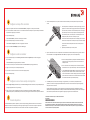
屏幕显示您需要进行的连接。
确保您拥有下列物品。在提供的空白处记下 IP 网络值。
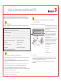
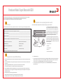
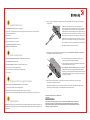
1. 将电源线连接至交换机和电源 (1) 电源和状态 LED 显
示琥珀色然后变为绿色。这可需要一至三分钟时间。
2. 使用以太网电缆(3 5)和以太网集线器或交换机(2)将
交换机和安装计算机连接到同一 LAN 请确保以太网集线
器或交换机连接到电源(6)
3. 如果要使用串行连接进行安装,则使用交换机(4)随
附的串行电缆将安装计算机 COM 端口(7)连接到该交换
机上的串行端口。串行连接设置如下:
• 每秒位数:9600
• 数据位:8
• 奇偶校验:无
• 停止位:1
• 流量控制:无
4. 单击下一步
。
• 如果选择了使用以太网连接,则随即显示查找交换机屏幕。按照查找交换机屏幕上的说明输入交换机 WWN
完成交换机查找之后,随即显示设置交换机 IP 地址屏幕。
• 如果选择了使用串行端口连接,则随即显示设置交换机 IP 地址屏幕。
完成本指南中的步骤以使用 EZSwitchSetup 安装 Brocade 6520 交换机并以单一交换机配置进行设置。如果要选择不
同的设置,请参阅
Brocade 6520 硬件参考手册和 Fabric OS 管理员指南
。
管理员指南
1
2
7
5
6
4
3

设置交换机 IP 地址
4
1. 在交换机的光纤信道端口中安装 SFP+ 收发器以匹配屏幕上所示的端口。
设置交换机密码
5
配置区域并执行设备选择
6
连接设备
7
!
© 2012 Brocade Communications Systems, Inc. 保留所有权利。
53-1002706-01
*53-1002706-01*
!
1. 在设置交换机 IP 地址屏幕上输入所需的信息。
2. 如果提示安装 Active X 或 Java Runtime 环境的版本,则请予以安装。如果需要,请重新引导安装计算机。
3. 单击下一步。
随即显示确认 IP 地址屏幕。
4. 单击下一步确认该地址。
随即显示继续配置屏幕。
5. 单击继续 EZManager。
1. 在EZManager 欢迎使用交换机配置屏幕,单击下一步。
随即显示设置参数屏幕。
2. 在设置参数屏幕,创建新管理员帐户密码。
3. 输入交换机的新名称(可选步骤)。
4. 调整您所在时区的日期和时间(可选步骤)。
5. 单击下一步。
1. 在选择分区
屏幕上选择典型分区,然后单击下一步 。
“典型分区”是默认的区域配置。
2. 在设备选择屏幕上输入您将要连接至交换机的设备数和类型。EZSwitchSetup 使用这些值在您的交换机上自动配
连接设备
屏幕根据在您配置区域和执行设备选择时输入的信息,以图形方式显示交换机与设备的连接。在您连接所指定
的设备之前,此屏幕将所有物理连接显示为 missing(丢失)。
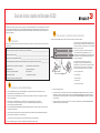
a. 该 16 Gbps SFP+ 收发器具有一个长的拔拉卡舌但没有闩锁线环。从要
使用的 SFP+ 收发器上卸下任何护塞,将每个 SFP+ 收发器按需定位并
插入(在顶排端口中右侧朝上,在底排端口中底侧朝上)。使用 16 Gbps
SFP+ 收发器上的拔拉卡舌将收发器推入端口中。
如果您使用 16 Gbps SFP+ 收发器,则可能先要将电缆连接到 SFP+,
然后将它们作为一个单元插入端口中。
如果您使用的是 8 或 10 Gbps SFP+ 收发器,则请合上闩锁线环。
b. 对其他端口重复此步骤。
a. 从光纤信道电缆终端卸下任何塑料护帽(如果有),然后定位电缆
连接器以便正确对齐。
b. 将电缆连接器插入 SFP+ 收发器直到稳固就位并且闩锁机件发出咔
嗒声。
c. 在您为交换机布线过程中,配置端口和连接设备
屏幕显示丢失、有
效、和无效连接。请注意,可能需要 15 秒钟时间连接才会显示为
有效连接。请确认所有连接均显示为绿色,然后单击下一步。
2. 对主机和存储设备进行物理连接。使配置端口和连接设备
屏幕所示的物理连接匹配。
3. 完成
屏幕将显示此消息:“Congratulations - you’ve successfully completed the setup!”(祝贺—您已成功完成安装!)
如果您使用了串行连接进行设置,则可以移除串行电缆。
EZManager 还有可用的附加配置选项例如自定义分区。请参阅 EZSwitchSetup 管理员指南了解有关自定义分区的更
多信息、以及其他交换机配置及管理选项。
Brocade、Brocade Assurance、B-wing 符号、BigIron、DCX、Fabric OS、FastIron、MLX、NetIron、SAN Health、ServerIron、TurboIron、VCS、
和
VDX 是 Brocade Communications Systems, Inc. 在美国和/或其他国家或地区的注册商标,并且 AnyIO、Brocade One、CloudPlex、
Effortless Networking、ICX、NET Health、OpenScript、和
Effortless Network 是 Brocade Communications Systems, Inc. 在美国和/或其他国家或
地区的商标。 所提及的其他品牌、产品、或服务名称则可能是其各自所有者的商标。
管理员指南

Brocade 6520 快速啟動指南
完成本指南中的步驟,於單一交換機組態中使用 EZSwitchSetup 安裝及設定您的 Brocade 6520 交換機。
如果您想選擇不同設定,請參閱 與 。
請確定您已備妥下列項目。請在所提供的空白處寫下 IP 網路值。
準備開始
交換機的固定 IP 位址 (IPv4 或 IPv6) (無 DHCP 伺服器): ______________________________________________________
子網路遮罩值: ________________________________________________________________________________________
預設閘道值: __________________________________________________________________________________________
Brocade 交換機的 World Wide Name (WWN):位於交換機 ID 標籤上: __________________________________________
乙太網路連線 (集線器或交換機) 乙太網路與光纖通道纜線
EZSwitchSetup 光碟 安裝電腦
已安裝 HBA 的主機電腦 磁碟陣列
標準螺絲起子 光纖 SFP+ 收發器
允許彈出視窗的瀏覽器
1
打開電源並將纜線連接至交換機
3
安裝並啟動 EZSwitchSetup
2
1. 將 EZSwitchSetup 光碟放入您的安裝電腦中的光碟機內。安裝程式將在約一分鐘內自動啟動。
2. 請遵循 EZSwitchSetup 指示進行安裝。在您按一下 OK (確定) 之後,安裝過程約需幾分鐘的時間。
3. 等待 EZSwitchSetup 開始執行,它會在完成安裝後自動執行。
有關 Windows 及 Linux 的說明,請參閱 EZSwitchSetup
。
4. 在 EZSwitchSetup 簡介畫面中,請選擇符合您的設定組態的選項:
• 乙太網路連線。此選項為您將用來執行 EZSwitchSetup 管理員的乙太區域網路連線。
• 使用序列纜線直接連接交換機。
大多數使用者會發現使用乙太網路連線更為便利。
5. 按一下 Next (下一步)。 隨即顯示 Connect Cables (連接纜線) 畫面。
4. 按一下 Next (下一步)。
• 如果您選擇使用乙太網路連線,將會顯示 Discover Switch (發線交換機) 畫面。輸入交換機的 WWN,然後遵循
Discover Switch (發現交換) 畫面的指示。完成發現交換機的步驟之後,將會顯示 Set Switch IP Address
(設定交換機 IP 位址) 畫面。
• 如果您選擇使用序列連接埠連接,會立即顯示 Set Switch IP Address (設定交換機 IP 位址) 畫面。
Connect Cables (連接纜線) 畫面會顯示您必須連接的連線。
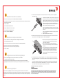
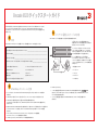
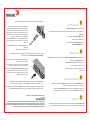
1. 將電源線連接至交換機及電源 (1)。電源與狀態 LED
會顯示琥珀色,然後顯示綠色。這需要一到三分鐘的時間。
2. 使用乙太網路線 (3、5) 以及乙太網路集線器或交
換機 (2),將交換機與安裝電腦連接至相同的區域網路。
請確定乙太網路集線器或交換機已連接電源 (6)。
3. 如果您要使用序列連線進行安裝,請使用與交換機 (4)
內附的序列纜線,將您的安裝電腦 COM 連接埠 (7) 連接至
交換機上的序列埠。序列連線的設定如下:
• 每秒傳輸位元:9600
• 資料位元:8
• 同位檢查:無
• 停止位元:1
• 流程控制:無
管理員指南
Brocade 6520 硬體參考手冊 Fabric OS 管理員指南
1
2
7
5
6
4
3

設定交換機 IP 位址
4
1. 在 Set Switch IP Address (設定交換機 IP 位址 ) 畫面中輸入必要的資訊。
2. 畫面中會提示您安裝 Active X 或某個版本的 Java 執行時期環境,請遵循提示進行安裝。如有需要,請重新啟動
安裝電腦。
3. 按一下 Next (下一步)。
隨即顯示Confirm IP Address (確認 IP 位址) 畫面。
4. 按一下 Next (下一步) 以確認位址。
隨即顯示 Continue Configuration (繼續設定) 畫面。
5. 按一下 Continue with EZManager (繼續使用 EZManager)。
1. 將 SFP+ 收發器安裝於交換機上的光纖通道連接埠以符合螢幕上所顯示的連接埠。
2. 實體連接您的主機與儲存裝置。實體連線必須符合 Configure Ports and Connect Devices (設定連接埠及連接裝置)
畫面所示的連接方式。
3. Finish (完成) 畫面將顯示此訊息:Congratulations - you’ve successfully completed the setup! (恭喜 - 您已成功完成設定!),
如果您使用序列連線進行設定,則可移除序列纜線。
請參閱 EZSwitchSetup
瞭解更多有關自訂區域與其他交換機組態和管理選項的資訊。
繼續使用 EZManager
5
1. 在 EZManager 上的 Welcome to Switch Configuration (歡迎至交換機設定) 的畫面上按一下 Next (下一步) 。
隨即顯示 Set Parameters (設定參數) 畫面。
2. 在 Set Parameters (設定參數) 中建立新的管理員帳戶密碼。
3. 輸入新的交換機名稱 (選擇性步驟)。
4. 調整您的時區的日期與時間 (選擇性步驟)。
5. 按一下 Next (下一步)。
設定區域並執行裝置選取
6
1. 在 Select Zoning (選取區域) 畫面中選取 Typical Zoning (典型區域) 並按一下 Next (下一步)。
預設區域設定為典型區域。
2. 在您要連線之交換機的 Device Selection (裝置選取) 畫面上輸入裝置類型。
EZSwitchSetup 會使用這些值自動組態交換機的連接埠。
連接裝置
7
Connect Devices (連接裝置) 畫面會依據您在設定區域並執行裝置選擇時所輸入的資訊,以圖形化的方式顯示交換機
與裝置的連線。此畫面將會顯示所有實體連線都是中斷的,直到您連接所指定的裝置為止。
a. 16 Gbps SFP+ 收發器上有一個長拉柄,沒有閂鎖纜線橫桿。移除您要
使用的 SFP+ 收發器上的所有保護蓋,並依照需要調整 SFP+ 收發器的
位置並將其插入 (連接上排的連接埠時必須右側朝上,連接下排的連接
埠時必須顛倒過來)。利用 16 Gbps SFP+ 收發器上的拉柄以便將收發器
插入連接埠。
如果您要使用 16 Gbps SFP+ 收發器,可能會想要先將纜線連接至 SFP+,
再將它插入連接埠形成一個單元。
如果您要使用 8 或 10 Gbps SFP+收發器,請關閉閂鎖纜線橫桿。
b. 在其他連接埠上重複執行此動作。
a. 將光纖通道纜線端的塑膠保護蓋 (如果有的話) 取下,然後調整纜線接
頭的位置以使其方向正確。
b. 將纜線接頭插入 SFP+ 收發機直到確實固定,而且閂鎖機構發出嚓聲。
c. 當您連接或拔除交換機的纜線時,Configure Ports and Connect Devices
(設定連接埠及連接裝置) 畫面會顯示中斷、有效及無效的連線。請注意,
插入纜線之後最長約需 15 秒才會將該連線顯示為有效的連線。請檢查
連線是否均顯示為綠色,然後按一下 Next (下一步 )。
!
© 2012 Brocade Communications Systems, Inc. 版權所有,翻印必究。
53-1002706-01
*53-1002706-01*
!
Brocade、Brocade Assurance、B-wing 標誌、BigIron、DCX、Fabric OS、FastIron、MLX、NetIron、SAN Health、ServerIron、TurboIron、VCS 及 VDX 為
Brocade Communications Systems, Inc. 在美國及
/或其他國家或地區之註冊商標;AnyIO、Brocade One、CloudPlex、Effortless Networking、ICX、
NET Health、OpenScript 以及 The Effortless Network 為 Brocade Communications Systems, Inc. 在美國及/或其他國家或地區之商標。本文中的其他品牌、
產品或服務名稱屬於其擁有者之商標或服務商標。
管理員指南

Guide de démarrage rapide Brocade 6520
Préparation
Adresse IP fixe (IPv4 ou IPv6) du commutateur (pas de serveur DHCP) : __________________________________________
Valeur de masque de sous-réseau : ________________________________________________________________________
Valeur de passerelle par défaut : ___________________________________________________________________________
Nom universel (WWN) du commutateur Brocade : situé sur la languette d'identification du commutateur : ______________
Connexion Ethernet (concentrateur ou commutateur) Câbles Ethernet et Fibre Channel
CD EZSwitchSetup Configuration de l'ordinateur
Ordinateur hôte avec HBA installé Matrice de disques
Tournevis standard Émetteurs - récepteurs SFP+ optiques
Navigateur qui permet l'affichage de fenêtres pop-up
1
Mise sous tension du commutateur et connexion des câbles
au commutateur
3
Installation et démarrage d'EZSwitchSetup
2
1. Insérez le CD EZSwitchSetup dans le lecteur CD-ROM de votre ordinateur de configuration. Le programme d'installation
démarrera automatiquement dans environ une minute.
2. Suivez les instructions d'installation d'EZSwitchSetup. L'installation prendra quelques minutes après que vous aurez
cliqué sur OK.
3. Attendez que EZSwitchSetup démarre, ce qui devrait se produire automatiquement une fois le programme installé.
Pour obtenir les instructions Windows et Linux, consultez le Guide de l'administrateur d'EZSwitchSetup.
4. Sur l'écran de Présentation d'EZSwitchSetup, sélectionnez l'option qui correspond à votre configuration :
• Connexion Ethernet. Cette option utilise la connexion LAN Ethernet que vous utiliserez pour exécuter EZSwitchSetup Manager.
• Connexion directe au commutateur avec un câble série.
La plupart des utilisateurs préféreront se servir de la connexion Ethernet.
5. Cliquez sur Suivant. L'écran Connecter les câbles s'affiche.
L'écran Connecter les câbles vous indique les connexions à établir.
Effectuez les étapes qui figurent dans ce guide pour installer et configurer votre commutateur Brocade 6520 en
configuration à un seul commutateur à l'aide d'EZSwitchSetup. Voir le Manuel de référence du matériel Brocade 6520
et le Guide de l'administrateur du système d'exploitation de la matrice si vous souhaitez choisir une autre configuration.
Assurez-vous que vous disposez des éléments répertoriés dans la liste ci-dessous. Notez les valeurs de réseau IP dans
l'espace prévu à cet effet.
1. Branchez le cordon d'alimentation au commutateur et
à la source d'alimentation (1). Les voyants d'alimentation
et d'état deviennent orange puis vert. Cela peut prendre
une à trois minutes.
2. Branchez le commutateur et l'ordinateur de
configuration au même réseau local à l'aide des câbles
Ethernet (3, 5) et d'un commutateur ou concentrateur
Ethernet (2). Assurez-vous que le commutateur ou le
concentrateur Ethernet est branché à une source
d'alimentation électrique (6).
3. Si vous souhaitez utiliser une connexion série pour la
configuration, connectez le port COM de votre ordinateur
de configuration (7) au port série du commutateur en
utilisant le câble série livré avec le commutateur (4).
Les paramètres de connexion série sont les suivants :
• Bits par seconde : 9600
• Bits de données : 8
• Parité : aucune
• Bits d'arrêt : 1
• Contrôle du flux : aucun
4. Cliquez sur Suivant.
• Si vous choisissez d'utiliser la connexion Ethernet, l'écran Découvrir le commutateur s'affiche. Saisissez le WWN du
commutateur selon les instructions à l'écran Découvrir le commutateur. Une fois la découverte du commutateur
terminée, l'écran Définir l'adresse IP du commutateur s'affiche.
• Si vous choisissez d'utiliser la connexion port série, l'écran Définir l'adresse IP du commutateur s'affiche
immédiatement.
1
2
7
5
6
4
3

Définition de l'adresse IP du commutateur
4
1. Installez les émetteurs-récepteurs SFP+ dans les ports Fibre Channel du commutateur pour y faire correspondre les
ports affichés à l'écran.
Définition du mot de passe du commutateur
5
Configuration des zones et sélection de périphériques
6
Connexion de périphériques
7
!
© 2012 Brocade Communications Systems, Inc. Tous droits réservés.
53-1002706-01
*53-1002706-01*
!
1. Saisissez les informations requises à l'écran Définir l'adresse IP du commutateur.
2. Si vous êtes invité à installer Active X ou une version de l'environnement Java Runtime, faites-le. Redémarrez l'ordinateur
de configuration, si nécessaire.
3. Cliquez sur Suivant.
L'écran Confirmer l'adresse IP s'affiche.
4. Cliquez sur Suivant pour confirmer les adresses.
L'écran Poursuivre la configuration s'affiche.
5. Cliquez sur Continuer avec EZManager.
1. Cliquez sur Suivant à l'écran d' EZManager Bienvenue à la configuration du commutateur.
L'écran Définir les paramètres s'affiche.
2. Créez un nouveau mot de passe pour le compte d'administrateur à l'écran Définir les paramètres.
3. Saisissez un nouveau nom pour le commutateur (étape facultative).
4. Réglez la date et l'heure selon votre fuseau horaire (étape facultative).
5. Cliquez sur Suivant.
1. Sélectionnez Fuseau typique à l'écran Sélectionner un fuseau et cliquez sur Suivant.
Il s'agit de la configuration de zone par défaut.
2. Saisissez le nombre et les types de périphériques que vous connectez au commutateur à l'écran Sélection de
périphériques. EZSwitchSetup utilise ces valeurs pour configurer automatiquement les ports sur votre commutateur.
L'écran Connecter des périphériques affiche une représentation graphique du commutateur avec les connexions de
périphérique selon les informations que vous avez entrées lors de la configuration des zones et la sélection de périphériques.
L'écran affichera toutes les connexions physiques comme manquantes tant que vous n'aurez pas connecté les périphériques
spécifiés.
a. Les émetteurs-récepteurs SFP+ 16 Gb/s présentent une longue languette
de préhension et aucune anse de verrouillage. Retirez toutes les fiches de
protection des émetteurs-récepteurs SFP+ que vous allez utiliser et insérez
chaque émetteur-récepteur SFP+ selon les instructions (à l'endroit dans la
rangée de ports supérieure et à l'envers dans la rangée inférieure de
ports). Utilisez la languette de préhension des émetteurs-récepteurs SFP+
16 Gb/s pour pousser l'émetteur-récepteur dans son port.
Si vous utilisez des émetteurs-récepteurs SFP+ à 16 Gb/s, vous voudrez
peut-être connecter le câble au SFP+ d'abord et ensuite les insérer dans le
port en bloc.
Si vous utilisez des émetteurs-récepteurs SFP+ 8 ou 10 Gb/s, fermez le
loquet de verrouillage.
b. Répétez cette procédure pour les autres ports.
a. Retirez les capuchons de protection en plastique des extrémités de
câble Fibre Channel (le cas échéant) et disposez le connecteur de
façon à l'orienter correctement.
b. Insérez le connecteur de câble dans l'émetteur-récepteur SFP+
jusqu'à ce qu'il soit bien installé et que le mécanisme de verrouillage
s'enclenche.
c. L'écran Configurer des ports et connecter des périphériques affiche
les connexions manquantes, valides et non valides lorsque vous
câblez le commutateur. Notez que jusqu'à 15 secondes peuvent
s'écouler avant l'affichage de la connexion en tant que connexion
valide. Vérifiez que les voyants des connexions sont tous verts, puis
cliquez sur Suivant.
2. Établissez les connexions physiques à votre hôte et aux périphériques de stockage. Faites correspondre les connexions
physiques affichées à l'écran Configurer les ports et connecter les périphériques.
3. L'écran Terminer affichera ce message : “Congratulations - you’ve successfully completed the setup!” (« Félicitations -
vous avez réussi la configuration ! »). Si vous avez utilisé la connexion série pour la configuration, vous pouvez retirer le
câble série.
Des options de configuration supplémentaires, telles que la définition de zone personnalisée, sont disponibles depuis
EZManager. Voir le Guide de l'administrateur d'EZSwitchSetup pour en savoir plus sur la définition personnalisée des
zones, ainsi que d'autres options de gestion et de configuration de commutateur.
Brocade, Brocade Assurance, le symbole B-wing, BigIron, DCX, Fabric OS, FastIron, MLX, NetIron, SAN Health, ServerIron, TurboIron, VCS et VDX sont des
marques déposées et AnyIO, Brocade One, CloudPlex, Effortless Networking, ICX, NET Health, OpenScript et The Effortless Network sont des marques de
Brocade Communications Systems, Inc. aux États-Unis et/ou dans d'autres pays. Les autres marques, produits ou noms de services cités peuvent être
des marques de leurs détenteurs respectifs.

Brocade 6520-Schnellstarthandbuch
Führen Sie die in diesem Handbuch aufgeführten Schritte aus, um Ihren Brocade 6520-Switch in einer Einzel-Switch-Konfiguration
mithilfe des Programms „EZSwitchSetup“ zu installieren. Wenn Sie ein anderes Setup auswählen möchten, finden Sie weitere
Informationen im sowie im .
Stellen Sie sicher, dass alle unten aufgeführten Komponenten vorliegen. Notieren Sie die IP-Netzwerkwerte in dem dafür
vorbereiteten Feld.
Vor dem Start
Feste IP-Adresse (IPv4 oder IPv6) für den Switch (kein DHCP-Server): ______________________________________________
Subnetzmaskenwert: _____________________________________________________________________________________
Standard-Gateway-Wert: ___________________________________________________________________________________
World Wide Name (WWN) des Brocade-Switches: befindet sich auf dem Auszug mit der Bezeichnung „Switch ID“:
____________
Ethernet-Verbindung (Hub oder Switch) Ethernet- und Fibre Channel-Kabel
EZSwitchSetup-CD Setup-Computer
Host-Computer mit installiertem HBA Festplatten-Array
Standardschraubenzieher Optische SFP+-Transceiver
Browser, der die Anzeige von Popup-Fenstern ermöglicht
1
Einschalten und Verbinden der Kabel mit dem Switch
3
Installieren und Starten von EZSwitchSetup
2
1. Legen Sie die EZSwitchSetup-CD in das CD-ROM-Laufwerk Ihres Setup-Computers ein. Das Installationsprogramm wird
nach etwa einer Minute gestartet.
2. Folgen Sie den EZSwitchSetup-Installationsanweisungen. Die Installation wird innerhalb weniger Minuten abgeschlossen,
nachdem Sie auf OK geklickt haben.
3. Warten Sie, bis EZSwitchSetup startet. Dieser Vorgang sollte nach der Installation automatisch ausgeführt werden.
Windows- und Linux-Anweisungen finden Sie im .
4. Wählen Sie auf dem Bildschirm EZSwitchSetup Introduction (EZSwitchSetup-Einführung) die Option aus, die Ihrer
Setupkonfiguration entspricht:
• Ethernet connection (Ethernet-Verbindung): Diese Option verwendet eine Ethernet-LAN-Verbindung, die Sie zum
Ausführen von EZSwitchSetup Manager verwenden können.
• „Direct connection to the switch with a serial cable“ (Direkte Verbindung mit dem Switch über ein serielles Kabel).
Die meisten Benutzer halten die Verwendung der Ethernet-Verbindung für komfortabler.
5. Klicken Sie auf Next (Weiter). Daraufhin wird der Bildschirm Connect Cables (Kabel verbinden) angezeigt.
4. Klicken Sie auf Next (Weiter).
• Wenn Sie die Verwendung der Ethernet-Verbindung gewählt haben, wird der Bildschirm Discover Switch
(Switch ermitteln) angezeigt. Geben Sie die Switch-WNN ein, und folgen Sie den Anweisungen auf dem Bildschirm
Discover Switch (Switch ermitteln). Nach Abschluss der Switch-Ermittlung wird der Bildschirm Set Switch IP Address
(IP-Adresse des Switches festlegen) angezeigt.
• Wenn Sie sich für die Verwendung der seriellen Schnittstellenverbindung entschieden haben, wird umgehend der
Bildschirm Set Switch IP Address (IP-Adresse des Switch festlegen) angezeigt.
Auf dem Bildschirm Connect Cables (Kabel verbinden) werden die erforderlichen Verbindungen dargestellt.
1. Schließen Sie das Stromkabel an den Switch und
an eine Stromquelle an (1). Die Stromversorgungs-
und Status-LEDs leuchten zunächst gelb, dann grün.
Dies kann bis zu drei Minuten dauern.
2. Schließen Sie den Switch und den Setup-Computer
mithilfe von Ethernet-Kabeln an das gleiche LAN (3, 5)
und an einen Ethernet-Hub oder Switch (2) an. Stellen
Sie sicher, dass der Ethernet-Hub oder der Switch an
eine Stromversorgung angeschlossen ist (6).
3. Wenn Sie eine serielle Verbindung für das Setup
verwenden möchten, schließen Sie den COM-Port
Ihres Setup-Computers (7) an den seriellen Anschluss
auf dem Switch an. Verwenden Sie dazu das serielle
Kabel, das im Lieferumfang Ihres Switches enthalten
ist (4). Die Einstellungen für die serielle Verbindung
lauten wie folgt:
• „Bits per second“ (Bit pro Sekunde): 9600
• „Databits“ (Datenbits): 8
• „Parity“ (Parität): none (keine)
• „Stop bits“ (Stopp-Bits): 1
• „Flow control“ (Datenflusssteuerung): none (keine)
EZSwitchSetup-Administratorhandbuch
1
2
7
5
6
4
3
Brocade 6520-Hardware-Referenzhandbuch Administratorhandbuch zum Fabric-Betriebssystem

Festlegen der IP-Adresse für einen Switch
4
1. Geben Sie die erforderlichen Daten auf dem Bildschirm Set Switch IP Address (IP-Adresse des Switches festlegen) ein.
2. Folgen Sie ggf. der Aufforderung, Active X oder eine Version der Java Runtime-Umgebung zu installieren, und führen Sie
anschließend ggf. einen Neustart des Setup-Computers durch.
3. Klicken Sie auf Next (Weiter).
Daraufhin wird der Bildschirm Confirm IP Address (IP-Adresse bestätigen) angezeigt.
4. Klicken Sie auf Next (Weiter), um die Adressen zu bestätigen.
Nun wird der Bildschirm Continue Configuration (Konfiguration fortsetzen) angezeigt.
5. Klicken Sie auf Continue with EZManager (Mit EZMananger fortfahren).
1. Installieren Sie die SFP+-Transceiver auf den Fibre Channel-Ports auf dem Switch entsprechend der auf dem Bildschirm
angegebenen Ports.
2. Stellen Sie die physischen Verbindungen zwischen Ihrem Host und den Speichergeräten her. Richten Sie sich dabei an
den physischen Verbindungen, die auf dem Bilschirm Configure Ports and Connect Devices (Ports konfigurieren und
Geräte verbinden) angezeigt werden.
3. Auf dem Bildschirm Finish (Fertig stellen) wird die folgende Meldung angezeigt: „Congratulations - you’ve successfully
completed the setup!“ (Herzlichen Glückwunsch - Sie haben das Setup erfolgreich abgeschlossen!). Wenn Sie die
serielle Verbindung für das Setup verwendet haben, können Sie das serielle Kabel jetzt entfernen.
In EZManager sind weitere Konfigurationsoptionen verfügbar, z. B. für die benutzerdefinierte Zoneneinteilung. Weitere
Informationen zur benutzerdefinierten Zoneneinteilung und zu weiteren Optionen für die Konfiguration und Verwaltung
von Switches finden Sie im EZSwitchSetup-Administratorhandbuch.
Festlegen des Switch-Kennworts
5
1. Klicken Sie auf dem EZManager-Bildschirm Welcome to Switch Configuration (Willkommen zur Switch-Konfiguration) auf
Next (Weiter).
Daraufhin wird der Bildschirm Set Parameters (Parameter festlegen) angezeigt.
2. Erstellen Sie auf dem Bildschirm Set Parameters (Parameter festlegen) ein neues Kennwort für das Administratorkonto.
3. Geben Sie einen neuen Namen für den Switch ein (optionaler Schritt).
4. Passen Sie Datum und Uhrzeit an Ihre Zeitzone an (optionaler Schritt).
5. Klicken Sie auf Next (Weiter).
Konfigurieren der Zonen und Auswählen von Geräten
6
1. Wählen Sie die Option Typical Zoning (Typische Zoneneinteilung) auf dem Bildschirm Select Zoning (Zoneneinteilung
auswählen) aus, und klicken Sie dann auf Next (Weiter).
„Typical Zoning“ (Typische Zoneneinteilung) ist die Standardzonenkonfiguration.
2. Geben Sie auf dem Bildschirm „Device Selection“ (Geräteauswahl) die Anzahl und Typen der Geräte ein, die Sie mit
dem Switch verbinden.
EZSwitchSetup konfiguriert mithilfe dieser Angaben automatisch die Ports auf Ihrem Switch.
Verbinden von Geräten
7
Auf dem Bildschirm Connect Devices (Geräte verbinden) wird eine grafische Darstellung des Switches mit seinen
Geräteverbindungen dargestellt. Als Basis für diese Darstellung dienen die Informationen, die Sie im Rahmen der
Konfiguration der Zonen und der Auswahl der Geräte eingegeben haben. Dieser Bildschirm zeigt alle physischen
Verbindungen so lange als fehlend an, bis Sie die von Ihnen angegebenen Geräte verbunden haben.
a. Die 16-GB/s-SFP+-Transceiver verfügen über eine lange Zuglasche und
keinen Anschlussdrahtbügel. Entfernen Sie alle Schutzstecker von den
SFP+-Transceivern, die Sie verwenden werden, und positionieren Sie
jeden SFP+-Transceiver nach Bedarf (in der richtigen Ausrichtung in der
oberen Reihe der Ports und umgekehrt in der unteren Reihe der Ports).
Verwenden Sie die Zuglasche der 16-GB/s-SFP+-Transceiver, um den
Transceiver dabei zu unterstützen, im Port einzurasten.
Wenn Sie 16-GB/s-SFP+-Transceiver verwenden, sollten Sie zunächst
das Kabel mit dem SFP+ verbinden und die Transceiver anschließend
als Einheit in den Port einsetzen.
Wenn Sie SFP+-Transceiver mit 8 oder 10 GB/s verwenden, schließen
Sie den Verriegelungsdrahtbügel.
b. Wiederholen Sie diese Schritte für alle anderen Ports.
a. Entfernen Sie die Kunststoffschutzkappen von den Fibre
Channel-Kabelenden (falls vorhanden), und positionieren Sie den
Kabelanschluss so, dass er korrekt ausgerichtet ist.
b. Fügen Sie den Kabelanschluss in den SFP+-Transceiver ein, bis er
fest sitzt und der Verriegelungsmechanismus hörbar einrastet.
c. Auf dem Bildschirm Configure Ports and Connect Devices (Ports
konfigurieren und Geräte verbinden) werden fehlende, gültige und
ungültige Verbindungen bei der Verkabelung des Switches angezeigt.
Beachten Sie, dass es bis zu 15 Minuten dauern kann, bis die
Verbindung als gültig angezeigt wird. Überprüfen Sie, dass sämtliche
Verbindungen grün angezeigt werden, und klicken Sie dann auf
Next (Weiter).
!
© 2012 Brocade Communications Systems, Inc. Alle Rechte vorbehalten.
53-1002706-01
*53-1002706-01*
!
Brocade, Brocade Assurance, das B-wing-Symbol, BigIron, DCX, Fabric OS, FastIron, MLX, NetIron, SAN Health, ServerIron, TurboIron, VCS und VDX sind
registrierte Marken, und AnyIO, Brocade One, CloudPlex, Effortless Networking, ICX, NET Health, OpenScript und The Effortless Network sind Marken von Brocade
Communications Systems, Inc. in den USA und/oder anderen Ländern. Andere hier nicht genannte Marken, Produkte oder Servicenamen sind möglicherweise
Marken ihrer jeweiligen Eigentümer.

Panduan Mulai Cepat Brocade 6520
Selesaikan langkah di dalam panduan ini untuk memasang dan menyetel switch Brocade 6520 Anda dalam konfigurasi
satu switch menggunakan EZSwitchSetup. Lihat Panduan Referensi Perangkat Keras Brocade 6520 dan
Panduan Administrator Fabric OS jika Anda ingin memilih penyetelan yang berbeda.
Pastikan Anda telah memiliki item-item yang tercantum di bawah ini. Tuliskan nomor jaringan IP di tempat yang disediakan.
Persiapan
Alamat IP tetap (IPv4 atau IPv6) untuk switch (tidak ada server DHCP): ____________________________________________
Nomor subnet mask: _____________________________________________________________________________________
Nilai Default Gateway: ____________________________________________________________________________________
World Wide Name (WWN) switch Brocade: terletak di label ID switch: _____________________________________________
Koneksi Ethernet (hub atau switch) Kabel Fibre Channel dan Ethernet
CD EZSwitchSetup Komputer penyetelan
Komputer host dengan HBA terinstal Rangkaian disk
Obeng standar Transceiver SFP+ Optis
Browser yang memungkinkan adanya jendela sembul (pop-up)
1
Menyalakan dan menyambungkan kabel ke switch
3
Menginstal dan memulai EZSwitchSetup
2
1. Masukkan CD EZSwitchSetup CD ke dalam drive CD-ROM pada komputer Anda. Installer akan dimulai otomatis dalam
satu menit.
2. Ikuti arahan EZSwitchSetup untuk penginstalan. Penginstalan akan memerlukan waktu beberapa menit setelah Anda
mengklik OK.
3. Tunggulah hingga EZSwitchSetup dimulai, yang seharusnya otomatis dimulai setelah diinstal.
Untuk instruksi Windows dan Linux, bacalah Panduan Administrator EZSwitchSetup.
4. Pada layar Introduction (Pendahuluan) EZSwitchSetup, pilih opsi yang cocok dengan konfigurasi pengaturan Anda:
• Sambungan Ethernet. Opsi ini menggunakan sambungan LAN Ethernet yang akan Anda gunakan untuk menjalankan
EZSwitchSetup Manager.
• Sambungan langsung ke switch menggunakan kabel seri.
Sebagian besar pengguna merasa lebih mudah menggunakan sambungan Ethernet.
5. Klik Next (Berikutnya). Layar Connect Cables (Sambungkan Kabel) akan ditampilkan.
4. Klik Next (Berikutnya).
• Jika Anda memilih menggunakan sambungan Ethernet, layar Discover Switch (Temukan Switch) akan ditampilkan.
Masukkan WWN switch, mengikuti instruksi di layar Discover Switch (Temukan Switch). Setelah menyelesaikan
penemuan switch, layar Set Switch IP Address (Atur Alamat Switch IP)akan ditampilkan.
• Jika Anda memilih menggunakan sambungan port seri, layar Set Switch IP Address (Atur Alamat Switch IP)
segera ditampilkan.
Layar Connect Cables (Sambungkan Kabel) menampilkan sambungan yang perlu Anda buat.
1. Sambungkan kabel daya ke switch dan ke sumber
daya (1). LED status dan daya menyala kuning lalu hijau.
Prosedur ini bisa memakan waktu satu hingga tiga menit.
2. Sambungkan switch dan komputer penyetelan ke LAN
yang sama, dengan menggunakan kabel Ethernet (3, 5)
dan switch atau hub Ethernet (2). Pastikan switch atau
hub Ethernet tersambung ke sumber daya (6).
3. Jika Anda ingin menggunakan sambungan seri untuk
penyetelan, sambungkan port COM komputer penyetelan (7)
ke port seri di switch, dengan menggunakan kabel seri yang
disertakan bersama switch (4). Pengaturan sambungan seri
adalah sebagai berikut:
• Bit per detik: 9600
• Databit: 8
• Paritas: tidak ada
• Bit stop: 1
• Kontrol aliran: tidak ada
1
2
7
5
6
4
3

Mengatur alamat switch IP
4
1. Masukkan informasi yang diperlukan pada layar Set Switch IP Address (Atur Alamat Switch IP).
2. Jika Anda diminta menginstal Active X atau versi Java runtime environment, lakukanlah. Booting ulang komputer,
jika diperlukan.
3. Klik Next (Berikutnya).
Layar Confirm IP Address (Konfirmasikan Alamat IP) akan ditampilkan.
4. Klik Next (Berikutnya) untuk mengonfirmasikan alamat.
Layar Continue Configuration (Lanjutkan Konfigurasi) akan ditampilkan.
5. Klik Continue with EZManager (Lanjutkan dengan EZManager).
1. Pasang port transceiver SFP+ di port Fibre Channel pada switch untuk memadankan port yang ditunjukkan di layar.
2. Buat sambungan fisik ke perangkat penyimpanan dan host Anda. Cocokkan dengan sambungan fisik yang ditampilkan di
layar Configure Ports and Connect Devices (Konfigurasikan Port dan Sambungkan Perangkat).
3. Layar Finish (Selesai) akan menampilkan pesan ini: "Congratulations - you’ve successfully completed the setup!"
("Selamat - Anda telah berhasil menyelesaikan penyetelan!") Jika Anda menggunakan sambungan seri penyetelan,
Anda dapat melepaskan kabel seri.
Opsi konfigurasi tambahan, seperti penzonaan kesukaan, tersedia di EZManager. Bacalah Panduan Administrator
EZSwitchSetup untuk informasi lebih lanjut tentang penzonaan kesukaan, opsi manajemen serta konfigurasi switch lain.
Atur kata sandi switch
5
1. Klik Next (Berikutnya) pada layar Welcome to Switch Configuration (Selamat Datang di Konfigurasi Switch) EZManager.
Layar Set Parameters (Atur Parameter) akan ditampilkan.
2. Buat kata sandi akun administrator yang baru dalam layar Set Parameters (Atur Parameter).
3. Masukkan nama baru untuk switch (langkah opsional).
4. Sesuaikan tanggal dan waktu untuk zona waktu Anda (langkah opsional).
5. Klik Next (Berikutnya).
Konfigurasikan zona dan lakukan pemilihan perangkat
6
1. Pilih Typical Zoning (Penzonaan Umum) pada layar Select Zoning (Pilih Penzonaan) dan klik Next (Berikutnya).
Typical Zoning (Penzonaan Umum) adalah konfigurasi zona default.
2. Masukkan jumlah dan tipe perangkat yang akan Anda sambungkan ke switch di layar Device Selection (Pilihan Perangkat).
EZSwitchSetup menggunakan nilai-nilai ini untuk mengonfigurasikan port di switch Anda secara otomatis.
Menyambungkan perangkat
7
Layar Connect Devices (Sambungkan Perangkat) menampilkan representasi grafis switch dengan sambungan perangkat
berdasarkan informasi yang telah Anda masukkan ketika mengonfigurasikan zona dan melakukan pemilihan perangkat.
Layar ini akan menunjukkan bahwa semua sambungan fisik tidak ditemukan hingga Anda menyambungkan perangkat yang
Anda tentukan.
a. Transceiver SFP+ 16 Gbps memiliki tab penarik yang panjang dan tidak
memiliki gagang kawat slot. Lepaskan semua sumbat pelindung dari
transceiver SFP+ yang akan digunakan, lalu posisikan serta sisipkan
setiap transceiver SFP+ sesuai keperluan (sisi kanan menghadap ke atas
pada baris port teratas dan menghadap ke bawah di baris bawah port).
Gunakan tab penarik pada transceiver SFP+ 16 Gbps untuk membantu
mendorong transceiver ke dalam port.
Jika Anda menggunakan transceiver SFP+ 16 Gbps, Anda mungkin perlu
menyambungkan kabelnya ke SFP+ terlebih dulu, lalu memasukkannya ke
dalam port sebagai satu unit.
Jika Anda menggunakan transceiver SFP+ 8 Gbps, tutup gagang kawat slot.
b. Ulangi untuk port lain.
a. Lepaskan tutup pelindung plastik dari ujung kabel Fibre Channel (jika ada),
dan posisikan konektor kabel sehingga diarahkan dengan benar.
b. Masukkan konektor kabel ke dalam SFP+ hingga terpasang dengan kuat
dan mekanisme slot telah terpasang tepat.
c. Layar Configure Ports and Connect Devices (Konfigurasikan Port dan
Sambungkan Perangkat) menunjukkan bahwa sambungan hilang, valid,
dan tidak valid ketika Anda menghubungkan kabel switch. Anda mungkin
memerlukan waktu hingga 15 detik sampai sambungan ditampilkan sebagai
sambungan yang valid. Periksa apakah semua sambungan sudah hijau,
lalu klik Next (Berikutnya).
!
© 2012 Brocade Communications Systems, Inc. Hak Cipta Dilindungi Undang-Undang.
53-1002706-01
*53-1002706-01*
!
Brocade, Brocade Assurance, simbol B-wing, BigIron, DCX, Fabric OS, FastIron, MLX, NetIron, SAN Health, ServerIron, TurboIron, VCS, dan VDX merupakan merek
dagang terdaftar, dan AnyIO, Brocade One, CloudPlex, Effortless Networking, ICX, NET Health, OpenScript, dan The Effortless Network merupakan merek dagang dari
Brocade Communications Systems, Inc., di Amerika Serikat dan/atau negara lain. Merek, produk, atau nama layanan lain yang disebutkan merupakan atau mungkin
merupakan merek dagang pemiliknya masing-masing.

Brocade 6520 クイックスタートガイド
本ガイドの手順に従って、EZSwitchSetup を使用した Brocade 6520 スイッチのシングルスイッチ構成でのインストールおよび
セットアップを行ってください。他の方法によるセットアップについては、『
Brocade 6520 Hardware Reference Manual』
(
Brocade 6520 ハードウェアリファレンスマニュアル)および『Fabric OS Administrator’s Guide』(Fabric OS 管理者ガイド)を
参照してください。
次にリストされるアイテムがそろっていることを確認してください。所定の空欄にネットワークの
IP 値を記入してください。
準備
スイッチの固定 IP アドレス(IPv4 または IPv6、DHCP サーバーなし): _________________________________________________
サブネットマスクの値: _____________________________________________________________________________________
デフォルトゲートウェイの値:_________________________________________________________________________________
Brocade スイッチのワールドワイド名(WWN):スイッチの引き出し式 ID ラベルに記載: ____________________________________
イーサネット接続(ハブまたはスイッチ) イーサネットケーブルおよびファイバチャネルケーブル
EZSwitchSetup CD セットアップ用コンピュータ
HBA インストール済みのホストコンピュータ ディスクアレイ
標準ネジまわし
光学 SFP+ トランシーバ
ポップアップウィンドウを許可するように設定したブラウザ
1
スイッチへの電源投入とケーブルの接続
3
EZSwitchSetup のインストールと起動
2
1. セットアップ用コンピュータの CD-ROM ドライブに EZSwitchSetup CD を挿入します。約 1 分ほどでインストーラが自動的に
起動します。
2. EZSwitchSetup が表示するインストール指示に従ってください。インストールには、OK をクリックした後、数分かかります。
3. EZSwitchSetup が起動するのを待ちます。通常は CD の挿入後に自動的に起動されます。
Windows および Linux 向け手順については、『EZSwitchSetup Administrator’s Guide』(EZSwitchSetup 管理者ガイド)を
参照してください。
4. 画面上に EZSwitchSetup のIntroduction(導入)画面が表示されたら、お使いのセットアップ設定に適合するオプションを選択します。
• Ethernet connection(イーサネット接続)。このオプションは、EZSwitchSetup Manager の実行にイーサネット LAN 接続を
使用します。
• Direct connection to the switch with a serial cable(シリアルケーブルを用いたスイッチへの直接接続)。
ほとんどのユーザーには、イーサネット接続を利用がより便利です。
5. Next(次へ)をクリックします。Connect Cables(ケーブルの接続)画面が表示されます。
4. Next(次へ)をクリックします。
• イーサネット接続を選択する場合には、Discover Swtich(スイッチの検出)画面が表示されます。スイッチの検出 画面の
指示に従って、スイッチの
WWN を入力してください。スイッチの検出が完了すると、Set Switch IP Addres(スイッチの
IP アドレスの設定)画面が表示されます。
• シリアルポート接続を選択する場合には、Set Switch IP Address(スイッチの IP アドレスの設定)画面がすぐに
表示されます。
Connect Cables(ケーブルの接続)画面には、行う必要のある接続内容が表示されます。
1. 電源コードを、スイッチおよび電源に接続します(1)。
電源およびステータス LED が最初橙色に点灯し、次に緑色に
変わります。これには 1~3 分かかります。
2. イーサネットケーブルを使って、スイッチとセットアップ用
コンピュータを同じ
LAN に接続し (3、5)、イーサネット用ハブ
またはスイッチも接続します
(2)。このイーサネット用ハブまたは
スイッチが電源に接続されていることを確認します
(6)。
3. シリアル接続を使ってセットアップを行う場合は、
セットアップ用コンピュータの
COM ポート (7) をスイッチの
シリアルポートに接続します。この接続には、スイッチに同梱の
シリアルケーブルを使用してください
(4)。シリアル接続の設定は
次のとおりです。
• 転送速度(bps):9600
• データビット:8
• パリティ:なし
• ストップビット:1
• フロー制御:なし
1
2
7
5
6
4
3

スイッチの IP アドレスの設定
4
1. スイッチの Set Switch IP Address(IP アドレスの設定)画面で必要な情報を入力します。
2. Active X または特定のバージョンの Java ランタイム環境をインストールするプロンプトが表示された場合は、
それに従ってインストールしてください。必要に応じて、セットアップ用コンピュータを再起動します。
3. Next(次へ)をクリックします。
Confirm IP Address(IP アドレスの確認)画面が表示されます。
4. Next(次へ)をクリックして、アドレスを確認します。
Continue Configuration(設定の継続)画面が表示されます。
5. Continue with EZManager(EZManager を続行)をクリックします。
1. 画面に表示されているポートと一致するように、SFP+ トランシーバをスイッチのファイバチャネルポートに取り付けます。
2. お使いのホストおよびストレージデバイスへの物理的な接続を行います。Configure Ports and Connect Devices(ポートの設定
およびデバイスの接続)画面に表示された物理接続に一致するように、物理接続を行います。
3. Finish(完了)画面に「Congratulations - you’ve successfully completed the setup!」(おめでとうございます、セットアップが
正しく完了しました)というメッセージが表示されます。セットアップにシリアル接続を使用した場合は、シリアルケーブルを
取り外すことができます。
カスタムゾーニングなどの追加の設定オプションは、EZManager からご利用いただけます。カスタムゾーニング、および
その他スイッチ設定と管理オプションについての詳細は、『
EZSwitchSetup Administrator’s Guide』(EZSwitch セットアップ
管理者ガイド)を参照してください。
スイッチパスワードの設定
5
1. EZManager の Welcome to Switch Configuration(スイッチ設定にようこそ)画面で Next (次へ)をクリックします。
Set Parameters(パラメータの設定)画面が表示されます。
2. Set Parameters(パラメータの設定)画面で、管理者アカウント用の新規パスワードを作成します。
3. スイッチの新しい名前を入力します(オプション)。
4. 居住地のタイムゾーンに合わせて日付と時刻を調整します(オプション)。
5. Next(次へ)をクリックします。
ゾーンの設定とデバイス選択の実行
6
1. Select Zoning(ゾーニングの選択)画面で Typical Zoning (標準ゾーニング)を選択し、Next (次へ)をクリックします。
標準ゾーニングは、デフォルトのゾーン設定です。
2. Device Selection(デバイスの選択)画面で、スイッチに接続するデバイスの数とタイプを入力します。
EZSwitchSetup はこれらの値を使用して、スイッチ上のポートを自動的に設定します。
デバイスの接続
7
ゾーン設定およびデバイス選択で入力された情報に基づいて、Connect Devices(デバイスの接続)画面に、スイッチと
デバイス接続の状況がグラフ表示されます。指定されたデバイスが実際に接続されるまでは、画面上の物理的接続は
すべて
「missing」(欠落)と表示されます。
a. 16 Gbps SFP+ トランシーバには長いプルタブがありますが、ラッチ式のワイヤ
留め具はありません。取り付ける
SFP+ トランシーバに付けられている保護プラグ
をすべて取り外し、各
SFP+ トランシーバを要件通りに配置して、挿入します
(上段のポートでは上下正しい向きにし、下段のポートでは上下逆向きにします)。
プルタブを使って
16 Gbps SFP+ トランシーバを挿入します。
16 Gbps SFP+ トランシーバを使用する場合、最初に SFP+ にケーブルを接続
してから、ひとまとめにポートに挿入することもできます。
8 または 10 Gbps SFP+ トランシーバを使用する場合は、ラッチ式のワイヤ
留め具を閉じます。
b. 他のポートについても同じ作業を繰り返してください。
a. ファイバチャネルケーブルの先端にプラスティックの保護キャップが付けられて
いる場合は、それらを取り外した後、ケーブルのコネクタを正しい向きに
配置します。
b. ケーブルコネクタが SFP+ トランシーバ内にしっかりと装着され、ラッチ機構が
カチッと働くまでケーブルを
SFP+ 内に挿入します。
c. スイッチにケーブル配線していくと、Configure Ports and Connect Devices
(ポートの設定およびデバイスの接続)画面にケーブル接続が missing(欠落)、
valid(有効)、および invalid(無効)と表示されます。接続が有効な接続として
表示されるまで最大
15 秒程度かかる場合があることに注意してください。
接続がすべて緑色であることを確認して、
Next(次へ)をクリックします。
!
© 2012 Brocade Communications Systems, Inc. All Rights Reserved.
53-1002706-01
*53-1002706-01*
!
Brocade、Brocade Assurance、B-wing シンボル、BigIron、DCX、Fabric OS、FastIron、MLX、NetIron、SAN Health、ServerIron、TurboIron、VCS、
および VDX は Brocad Communications Systems, Inc. の米国および / またはその他の国々における登録商標で、AnyIO、Brocade One、CloudPlex、
Effortless Networking、ICX、NET Health、OpenScript、および The Effortless Network は Brocade Communications Systems, Inc. の米国および / またはそ
の他の国々における商標です。本書で使用されるその他のブランド、製品、またはサービス名は、それぞれの権利所有者に帰属す
る商標である可能性があります。

Brocade 6520 빠른 시작 안내서
EZSwitchSetup을 사용하여 단일 스위치 구성에서 Brocade 6520 스위치를 설치하고 설정하려면 이 안내서의 단계를
완료하십시오. 다른 설치를 선택하려면 를 참조하십시오.
하기 나열된 항목을 보유하고 있는지 확인합니다. 해당 필드에 IP 네트워크 값을 입력합니다.
준비하기
해당 스위치(DHCP 서버 없음)에 대한 고정 IP 주소 (IPv4 또는 IPv6): ____________________________________________
서브넷 마스크 값:________________________________________________________________________________________
기본 게이트웨이 값: _____________________________________________________________________________________
Brocade 스위치 월드 와이드 이름 (WWN): 스위치 ID 페이지에 위치: ____________________________________________
이더넷 연결 (허브 또는 스위치) 이더넷 및 파이버 채널 케이블
EZSwitchSetup CD 컴퓨터 설치
HBA 장착 호스트 컴퓨터 디스크 어레이
표준 스크류 드라이버 광학 SFP+ 트랜시버
팝업 창을 허용하는 브라우저
1
전원 켜기 및 스위치에 케이블 연결하기
3
EZSwitchSetup 설치 및 시작
2
1. 설치 컴퓨터의 CD-ROM 드라이브에 EZSwitchSetup CD를 넣습니다. 설치 프로그램이 1분 안에 자동 설치됩니다.
2. 설치를 위한 EZSwitchSetup 지침을 따릅니다. 설치는 OK(확인)를 클릭한 후에 몇 분 정도 걸립니다.
3. EZSwitchSetup은 설치 후 자동으로 시작되므로 시작할 때까지 기다립니다.
Windows 및 Linux 지침에 대한 내용은 EZSwitchSetup 관리자 설명서를 참조하십시오.
4. EZSwitchSetup Introduction(소개) 화면에서 설치 구성과 일치하는 옵션을 선택합니다.
• 이더넷 연결. 이 옵션은 EZSwitchSetup 관리자를 실행하는 데 사용할 이더넷 LAN 연결을 사용합니다.
• 직렬 케이블을 사용하여 스위치에 직접 연결합니다.
대다수의 사용자들은 이더넷 연결을 사용하는 것이 보다 편리하다는 점을 알게 됩니다.
5. Next(다음)을 클릭합니다. Connect Cables(케이블 연결) 화면이 표시됩니다.
1. 설치 컴퓨터의 CD-ROM 드라이브에 EZSwitchSetup CD를 넣습니다. 설치 프로그램이 1분 안에 자동 설치됩니다.
2. 설치를 위한 EZSwitchSetup 지침을 따릅니다. 설치는 OK(확인)를 클릭한 후에 몇 분 정도 걸립니다.
3. EZSwitchSetup은 설치 후 자동으로 시작되므로 시작할 때까지 기다립니다.
Windows 및 Linux 지침에 대한 내용은 를 참조하십시오.
4. EZSwitchSetup Introduction(소개) 화면에서 설치 구성과 일치하는 옵션을 선택합니다.
• 이더넷 연결. 이 옵션은 EZSwitchSetup 관리자를 실행하는 데 사용할 이더넷 LAN 연결을 사용합니다.
• 직렬 케이블을 사용하여 스위치에 직접 연결합니다.
대다수의 사용자들은 이더넷 연결을 사용하는 것이 보다 편리하다는 점을 알게 됩니다.
5. Next(다음)을 클릭합니다. Connect Cables(케이블 연결) 화면이 표시됩니다.
4. Next(다음)를 클릭합니다.
• 이더넷 연결을 선택하는 경우 Discover Switch(스위치 검색) 화면이 나타납니다. 스위치 WWN을 입력하고
Discover Switch(스위치 검색) 화면의 지침을 따릅니다. 스위치 검색을 완료한 후에는 Set Switch IP Address
(스위치 IP 주소 설정) 화면이 나타납니다.
• 직렬 포트 연결을 사용하도록 선택한 경우 Set Switch IP Address(스위치 IP 주소 설정) 화면이 바로 나타납니다.
Connect Cables(케이블 연결) 화면에 사용자가 연결해야 할 항목이 나타납니다.
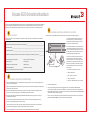
1. 전원 코드를 스위치 및 전원 (1)에 연결합니다. 전원
및 상태 LED가 황색을 나타낸 다음 녹색을 나타냅니다.
여기에는 1~3분 정도 소요됩니다.
2. 이더넷 케이블(3, 5) 및 이더넷 허브 또는 스위치(2)
를 사용하여 스위치 및 설치 컴퓨터를 동일한 LAN에
연결합니다. 이더넷 허브 또는 스위치에 전원(6)이
연결되어 있는지 반드시 확인합니다.
3. 직렬 연결 방식으로 설정하려는 경우 COSSM 포트(7)
를 스위치(4)와 함께 제공된 직렬 케이블을 사용하여
설치 컴퓨터 COM 포트(7)를 직렬 포트에 연결합니다.
직렬 연결 설정은 다음과 같습니다.
• 초당 비트: 9600
• 데이터 비트: 8
• 패리티: 없음
• 정지 비트: 1
• 흐름 제어: 없음
Brocade 6520 하드웨어 참조 매뉴얼 및 Fabric OS 관리자 설명서
EZSwitchSetup 관리자 설명서
1
2
7
5
6
4
3

스위치 IP 주소 설정하기
4
1. Set Switch IP Address(스위치 IP 주소 설정) 화면에 필요한 정보를 입력합니다.
2. Active X 또는 Java 런타임 환경 버전을 설치하라는 메시지가 나타나면 설치합니다. 필요한 경우 설치 컴퓨터를
다시 부팅합니다.
3. Next(다음)를 클릭합니다.
Confirm IP Address(IP 주소 확인) 화면이 나타납니다.
4. Next(다음)를 클릭하여 주소를 확인합니다.
Continue Configuration(구성 계속) 화면이 나타납니다.
5. Continue with EZManager(EZManager를 사용하여 계속)를 클릭합니다.
1. 스위치의 파이버 채널 포트에 SFP+ 트랜스시버를 설치하여 화면에 표시되는 포트와 일치시킵니다.
2. 호스트 및 스토리지 장치에 물리적으로 연결합니다. Configure Ports and Connect Devices(포트 구성 및 장치 연결)
화면에 표시되는 물리적 연결과 일치시킵니다.
3. Finish(완료) 화면에 “Congratulations - you’ve successfully completed the setup!” (축하합니다 - 설정을 성공적으로
완료했습니다!)라는 메시지가 나타납니다. 설치에 직렬 연결을 사용한 경우 직렬 케이블을 분리할 수 있습니다.
사용자 지정 존 지정과 같은 추가 구성 옵션을 EZManager에서 사용할 수 있습니다. 사용자 지정 존 지정 및 기타
스위치 구성과 관리 옵션에 대한 자세한 내용은 EZSwitchSetup 관리자 설명서를 참조하십시오.
스위치 암호 설정
5
1. EZManager Welcome to Switch Configuration(EZManager 스위치 구성 시작) 화면에서 Next(다음)를 클릭합니다.
Set Parameters(매개변수 설정) 화면이 나타납니다.
2. Set Parameters(매개변수 설정) 화면에서 새 관리자 계정 암호를 생성합니다.
3. 스위치에 대한 새 이름을 입력합니다(선택적 단계).
4. 시간대에 대한 날짜 및 시간을 조정합니다(선택적 단계).
5. Next(다음)를 클릭합니다.
존 구성 및 장치 선택 수행
6
1. Select Zoning(존 지정 선택) 화면에서 Typical Zoning(일반 존 지정)을 선택하고 Next(다음)를 클릭합니다.
일반 존 지정이 기본 존 구성입니다.
2. Device Selection(장치 선택) 화면에서 스위치에 연결할 장치 번호와 유형을 입력합니다.
EZSwitchSetup은 이 값을 사용하여 스위치에서 포트를 자동으로 구성합니다.
1. Select Zoning(존 지정 선택) 화면에서 Typical Zoning(일반 존 지정)을 선택하고 Next(다음)를 클릭합니다.
일반 존 지정이 기본 존 구성입니다.
2. Device Selection(장치 선택) 화면에서 스위치에 연결할 장치 번호와 유형을 입력합니다.
EZSwitchSetup은 이 값을 사용하여 스위치에서 포트를 자동으로 구성합니다.
장치 연결
7
Connect Devices(장치 연결) 화면에서는 존 구성 및 장치 선택 수행 시 입력된 정보를 기반으로 장치 연결을 한
스위치에 대한 그래픽 표현을 표시합니다. 화면에는 사용자가 지정한 장치를 연결할 때까지 누락된 모든 물리적
연결이 표시됩니다.
a. 16Gbps SFP+ 트랜스시버에는 긴 당김 탭은 있지만 래칭 와이어 베일은
없습니다.사용하고자 하는 SFP+ 트랜스시버에서 모든 보호 플러그를
분리한 다음 필요에 따라 각 SFP+ 트랜스시버의 위치를 정하여
삽입합니다(포트 상단에 우측으로, 포트 하단에 거꾸로). 16Gbps SFP+
트랜스시버의 당김 탭을 이용하면 트랜스시버를 포트에 밀어 넣는데
도움이 됩니다.
16Gbps SFP+ 트랜스시버를 이용하는 경우, 케이블을 우선 SFP+에
연결하고자 할 수도 있는데 그런 다음에는 포트에 하나의 유닛으로
삽입합니다.
8 또는 10Gbps SFP+ 트랜시버를 사용하는 경우 래칭 와이어 베일을
닫습니다.
b. 다른 포트에 대해 반복합니다.
a. 파이버 채널 케이블에서 플라스틱 보호 캡을 분리(있는 경우)한 후
적절한 방향이 되도록 케이블 커넥터의 위치를 지정합니다.
b. 단단히 고정되고 래칭 메커니즘이 딸깍 소리를 낼 때까지 SFP+에
케이블 커넥터를 밀어 넣습니다.
c. Configure Ports and Connect Devices(포트 구성 및 장치 연결) 화면에
누락된 연결, 유효한 연결, 무효한 연결이 나타납니다. 해당 연결을
유효한 연결로 나타내는 데 최대 15초가 소요될 수 있습니다.연결
표시등이 모두 녹색인지 확인한 후 Next(다음)를 클릭합니다.
a. 파이버 채널 케이블에서 플라스틱 보호 캡을 분리(있는 경우)한 후
적절한 방향이 되도록 케이블 커넥터의 위치를 지정합니다.
b. 단단히 고정되고 래칭 메커니즘이 딸깍 소리를 낼 때까지 SFP+에
케이블 커넥터를 밀어 넣습니다.
c. Configure Ports and Connect Devices(포트 구성 및 장치 연결) 화면에
누락된 연결, 유효한 연결, 무효한 연결이 나타납니다. 해당 연결을
유효한 연결로 나타내는 데 최대 15초가 소요될 수 있습니다.연결
표시등이 모두 녹색인지 확인한 후 Next(다음)를 클릭합니다.
!
© 2012 Brocade Communications Systems, Inc저작권 본사 소유.
53-1002706-01
*53-1002706-01*
!
Brocade, Brocade Assurance, B-wing 기호, BigIron, DCX, Fabric OS, FastIron, MLX, NetIron, SAN Health, ServerIron, TurboIron, VCS 및 VDX는 등록 상표이며 AnyIO,
Brocade One, CloudPlex, Effortless Networking, ICX, NET Health, OpenScript 및 The Effortless Network는 미국 및/또는 기타 국가에서 Brocade Communications
Systems, Inc. 의 상표입니다. 기타 언급된 브랜드, 제품, 또는 서비스명은 각 소유권자의 상표일 수 있습니다.

Guia de Início Rápido do Brocade 6520
Execute o procedimento descrito neste guia para instalar e configurar o comutador Brocade 6520 em uma configuração de
um único comutador, usando o EZSwitchSetup. Consulte os documentos Brocade 6520 Hardware Reference Manual
(Manual de Referência do Hardware Brocade 6520) e Fabric OS Administrator’s Guide (Guia do Administrator do Fabric OS)
se você quiser escolher uma outra configuração.
Verifique se você tem os itens mostrados na lista abaixo. Insira os valores da rede IP no espaço fornecido.
Preparação
Endereço IP fixo (IPv4 ou IPv6) do comutador (sem servidor DHCP): ______________________________________________
Valor da máscara de sub-rede: _____________________________________________________________________________
Valor do gateway padrão: __________________________________________________________________________________
Nome WWN (World Wide Name) do comutador Brocade: localizado na etiqueta de ID do comutador:
_________________________
Conexão Ethernet (hub ou comutador) Cabos Ethernet e de canal de fibra
CD EZSwitchSetup Computador de configuração
Computador host com um HBA instalado Matriz de disco
Chave de fenda padrão Transceptores óticos SFP+
Navegador que permita janelas pop-up
1
Ligar e conectar os cabos ao comutador
3
Instalar e iniciar o EZSwitchSetup
2
1. Insira o CD do EZSwitchSetup na unidade de CD-ROM do computador de configuração. O instalador iniciará
automaticamente dentro de aproximadamente um minuto.
2. Siga as instruções para a instalação do EZSwitchSetup. O processo de instalação levará alguns minutos para
ser iniciado após você clicar em OK.
3. Aguarde o EZSwitchSetup iniciar, o que deve acontecer automaticamente após ele ser instalado. Para obter instruções para
o Windows e Linux, consulte o documento EZSwitchSetup Administrator’s Guide (Guia do Administrador do EZSwitchSetup)
.
4. Na tela Introduction (Introdução) do EZSwitchSetup , escolha a opção que corresponda à sua configuração da instalação:
• Ethernet connection (Conexão de Ethernet). Esta opção usa a conexão de LAN Ethernet que será usada para executar o
gerenciador do EZSwitchSetup.
• Conexão direta ao comutador com um cabo serial.
A maioria dos usuários acha mais conveniente usar a conexão Ethernet.
5. Clique em Next (Avançar). A tela Connect Cables (Conexão de cabos) é mostrada.
4. Clique em Next (Avançar).
• Se você escolher a conexão Ethernet, a tela Discover Switch (Descobrir o comutador) é mostrada. Digite o nome
mundial (WWN) do comutador, seguindo as instruções apresentadas na tela Discover Switch. Após a descoberta do
comutador ser concluída, a tela Set Switch IP Address (Configurar o endereço IP do comutador) será mostrada.
• Se você optar por usar a conexão de porta serial, a tela Set Switch IP Address (Definir o endereço IP do comutador)
será mostrada imediatamente.
A tela Connect Cables (Conexão de cabos) mostra as conexões que você precisa fazer.
1. Conecte o cabo de alimentação ao comutador e à fonte
de energia (1). Os LEDs de alimentação e de status são
mostrados na cor âmbar e depois verde. Este processo pode
durar de um a três minutos.
2. Conecte o comutador e o computador de configuração à
mesma LAN, usando cabos Ethernet (3, 5) e um hub ou
comutador Ethernet (2). Verifique se o hub ou comutador
Ethernet está conectado a uma fonte de energia (6).
3. Se você quiser usar uma conexão serial para a
configuração, conecte a porta COM (7) do computador de
configuração à porta serial do comutador, usando o cabo
serial fornecido com o comutador (4). As configurações de
conexão serial são as seguintes:
• Bits por segundo: 9600
• Bits de dados: 8
• Paridade: nenhuma
• Bits de parada: 1
• Controle de fluxo: nenhum
1
2
7
5
6
4
3

Configurar o endereço IP do comutador
4
1. Digite as informações necessárias na tela Set Switch IP Address (Configurar o endereço IP do comutador).
2. Se você for solicitado a instalar o Active X ou uma versão do ambiente de execução Java, faça a instalação. Reinicialize o
computador de configuração, se necessário.
3. Clique em Next (Avançar).
A tela Confirm IP Address (Confirmar o endereço IP) é mostrada.
4. Clique em Next (Avançar) para confirmar os endereços.
A tela Continue Configuration (Continuar a configuração) é mostrada.
5. Clique em Continue with EZManager (Continuar o EZManager).
1. Instale os transceptores SFP+ nas portas de canal de fibra do comutador para corresponderem às portas mostradas
na tela.
2. Faça as conexões físicas ao host e aos dispositivos de armazenamento. Essas conexões precisam ser iguais às conexões
físicas mostradas na tela Configure Ports and Connect Devices (Configurar portas e conectar dispositivos).
3. A tela Finish (Concluir) irá mostrar esta mensagem: “Congratulations - you’ve successfully completed the setup!”
(Parabéns, você concluiu a configuração satisfatoriamente). Se você tiver usado a conexão serial para a configuração,
você pode remover o cabo serial.
Opções adicionais de configuração, como o zoneamento personalizado, estão disponíveis no EZManager. Consulte o
documento EZSwitchSetup Administrator’s Guide (Guia do Administrador do EZSwitchSetup) para obter mais informações
sobre zoneamento personalizado e outras opções de configuração e gerenciamento de comutadores.
Configurar a senha do comutador
5
1. Clique em Next (Avançar) na tela do EZManager Welcome to Switch Configuration (Bem-vindo à configuração
do comutador).
A tela Set Parameters (Configurar parâmetros) é mostrada.
2. Crie uma nova senha para a conta de administrador na tela Set Parameters (Configurar parâmetros).
3. Digite um novo nome para o comutador (etapa opcional).
4. Ajuste a data e a hora de acordo com o seu fuso horário (etapa opcional).
5. Clique em Next (Avançar).
Configurar as zonas e fazer a seleção de dispositivos
6
1. Selecione Typical Zoning (Zoneamento típico) na tela Select Zoning (Selecionar zoneamento) e clique em Next (Avançar).
A configuração padrão de zona é Typical Zoning.
2. Digite o número e os tipos de dispositivos que você está conectando ao comutador na tela Device Selection
(Seleção de dispositivos). O EZSwitchSetup usa estes valores para configurar automaticamente as portas do comutador.
Conectar dispositivos
7
A tela Connect Devices (Conectar dispositivos) mostra uma representação gráfica do comutador com as conexões de
dispositivos com base nas informações que você digitou quando configurou as zonas e fez a seleção dos dispositivos.
A tela mostrará todas as conexões físicas como ausentes até você conectar os dispositivos especificados.
a. Os transceptores SFP+ de 16 Gbps têm uma aba de puxar longa e nenhum
engate com fio. Remova todos os plugues protetores dos transceptores SFP+
que você for usar e posicione e insira cada transceptor SFP+ como exigido
(canto direito para cima na fila superior de portas e de cabeça para baixo
na fila inferior de portas). Use a aba de puxar nos transceptores SFP+ de
16 Gbps para ajudar a pressionar o transceptor na porta.
Se você estiver usando transceptores SFP+ de 16 Gbps, primeiro conecte
o cabo ao SFP+ e depois insira o transceptor na porta, como uma unidade.
Se você estiver usando transceptores SFP+ de 8 ou 10 Gbps, feche o
engate com fio.
b. Repita este procedimento para as outras portas.
a. Remova as tampas plásticas de proteção das extremidades do cabo de
canal de fibra (se houver alguma) e posicione o conector do cabo na
orientação correta.
b. Insira o conector do cabo no transceptor SFP+ até ele estar firmemente
assentado e você ouvir o clique indicando que o mecanismo está encaixado.
c. A tela Configure Ports and Connect Devices (Configurar portas e conectar
dispositivos) mostra as conexões ausentes, válidas e inválidas, conforme
você faz o cabeamento do comutador. Note que pode levar até 15 segundos
para a conexão ser mostrada como uma conexão válida. Confirme se todas
as conexões estão verdes e clique em
Next
(Avançar).
!
© 2012 Brocade Communications Systems, Inc. Todos os direitos reservados.
53-1002706-01
*53-1002706-01*
!
Brocade, Brocade Assurance, o símbolo de B em forma de asa, BigIron, DCX, Fabric OS, FastIron, MLX, NetIron, SAN Health, ServerIron, TurboIron, VCS e VDX são
marcas registradas e AnyIO, Brocade One, CloudPlex, Effortless Networking, ICX, NET Health, OpenScript e The Effortless Network são marcas comerciais da
Brocade Communications Systems, Inc. nos Estados Unidos e/ou em outros países. Os demais nomes de marcas, produtos ou serviços aqui mencionados podem
ser marcas comerciais dos seus respectivos proprietários.

Guía de inicio rápido de Brocade 6520
Complete los pasos de esta guía para instalar y configurar el conmutador Brocade 6520 en una configuración de conmutador
único mediante EZSwitchSetup. Consulte el Brocade 6520 Hardware Reference Manual(Manual de referencia de hardware
de Brocade 6520) y la Fabric OS Administrator’s Guide(Guía del Administrador de redes Fabric SO) si desea seleccionar una
configuración diferente.
Asegúrese de que dispone de todos los elementos que aparecen a continuación. Escriba los valores de red IP en el espacio
proporcionado.
Introducción
Dirección IP fija (IPv4 o IPv6) para el conmutador (ningún servidor DHCP): _____________________________________
_
___
Valor de máscara de subred: _________________________________________________________________________
__
____
Valor de puerta de enlace predeterminada: ______________________________________________________________
__
___
Nombre World Wide Name (WWN) del conmutador Brocade: ubicado en la etiqueta de Id. del conmutador: ___________________
Conexión Ethernet (concentrador o conmutador) Cables deEthernet y de Fibre Channel
CD EZSwitchSetup Equipo de configuración
Equipo host con un HBA instalado Matriz de discos
Destornillador estándar Transceptores SFP+ ópticos
Navegador que permita ventanas emergentes
1
Cómo encender y conectar los cables al conmutador
3
Instalación e inicio de EZSwitchSetup
2
1. Inserte el CD EZSwitchSetup en la unidad de CD-ROM de su equipo de configuración. El instalador se iniciará
automáticamente en aproximadamente un minuto.
2. Siga las instrucciones de EZSwitchSetup para la instalación. Ésta tardará unos minutos en completarse después de
hacer clic en OK (Aceptar).
3. Espere a que se inicie EZSwitchSetup, lo cual debería ocurrir automáticamente tras la instalación.
Para consultar las instrucciones de Windows y Linux, consulte la EZSwitchSetup Administrator’s Guide
(Guía del Administrador de EZSwitchSetup).
4. En la pantalla EZSwitchSetup Introduction (Introducción de EZSwitchSetup), seleccione la opción que coincida con su
configuración de instalación:
• Conexión Ethernet. Está opción utiliza la conexión LAN Ethernet que utilizará para ejecutar EZSwitchSetup Manager.
• Conexión directa al conmutador con un cable de serie.
La mayoría de usuarios considerarán que es más conveniente utilizar la conexión Ethernet.
5. Haga clic en Next (Siguiente). Se mostrará la pantalla Connect Cables (Conectar cables).
4. Haga clic en Next (Siguiente).
• Si seleccionó utilizar la conexión Ethernet, se mostrará la pantalla Discover Switch (Buscar conmutador). Introduzca
el WWN del conmutador, siguiendo las instrucciones en la pantalla Discover Switch (Buscar conmutador). Después
de completar una búsqueda de conmutador, se mostrará la pantalla Set Switch IP Address (Establecer la dirección IP
del conmutador).
• Si seleccionó utilizar la conexión del puerto de serie, se mostrará inmediatamente la pantalla Set Switch IP Address
(Establecer la dirección IP del conmutador).
La pantalla Connect Cables (Conectar cables) muestra las conexiones que necesita realizar.
1. Conecte el cable de alimentación al conmutador y a una
fuente de energía (1). Se mostrarán los LED de alimentación
y de estado en ámbar y, a continuación, en verde. Esto puede
llevar de uno a tres minutos.
2. Conecte el conmutador y el equipo de configuración
a la misma LAN utilizando cables Ethernet (3, 5) y un
concentrador o conmutador Ethernet (2). Asegúrese de que
el concentrador o conmutador Ethernet esté conectado a
una fuente de energía (6).
3. Si desea utilizar una conexión en serie para la
configuración, conecte el puerto COM del equipo de
configuración (7) al puerto serie del conmutador utilizando
el cable serie que se envió junto con el conmutador (4).
Los valores de la conexión en serie son los siguientes:
• Bits por segundo: 9600
• Bits de datos: 8
• Paridad: ninguna
• Bits de paro: 1
• Control de flujo: ninguno
1
2
7
5
6
4
3

Configuración de la dirección IP del conmutador
4
1. Introduzca la información necesaria en la pantalla Set Switch IP Address (Establecer la dirección IP del conmutador).
2. Si se le pide que instale Active X o una versión de Java runtime environment, hágalo. Reinicie el equipo de configuración
si es necesario.
3. Haga clic en Next (Siguiente).
Se mostrará la pantalla Confirm IP Address (Confirmar dirección IP).
4. Haga clic en Next (Siguiente) para confirmar las direcciones.
Se mostrará la pantalla Continue Configuration (Continuar con la configuración).
5. Haga clic en Continue with EZManager (Continuar con EZManager).
1. Instale los transceptores SFP+ en los puertos Fibre Channel del conmutador para que coincida con los puertos mostrados
en la pantalla.
2. Efectúe las conexiones físicas al host y a los dispositivos de almacenamiento, haciendo coincidir las conexiones físicas que
se muestran en la pantalla Configure Ports and Connect Devices (Configurar puertos y conectar dispositivos).
3. La pantalla Finish (Terminar) mostrará este mensaje: “Congratulations - you’ve successfully completed the setup!”
(“Enhorabuena, la configuración se ha completado correctamente”). Si ha utilizado la conexión serie para la configuración,
puede retirar el cable serie.
Las opciones de configuración adicionales, tales como la agrupación por zonas personalizada, están disponibles en
EZManager. Consulte la EZSwitchSetup Administrator’s Guide (Guía del Administrador de EZSwitchSetup) para obtener más
información sobre la agrupación por zonas personalizada y otras opciones de configuración y administración del conmutador.
Establezca la contraseña del conmutador
5
1. Haga clic en Next (Siguiente) en la pantalla Welcome to Switch Configuration (Bienvenido a la configuración del conmutador)
de EZManager.
Se mostrará la pantalla Set Parameters (Establecer parámetros).
2. Cree una nueva contraseña de cuenta del administrador en la pantalla Set Parameters (Establecer parámetros).
3. Introduzca un nombre para el conmutador (paso opcional).
4. Modifique la fecha y hora para su zona horaria (paso opcional).
5. Haga clic en Next (Siguiente).
Configuración de zonas y selección de dispositivos
6
1. Seleccione Typical Zoning (Agrupación por zonas típica) en la pantalla Select Zoning (Seleccionar agrupación por zonas) y
haga clic en Next (Siguiente).
La agrupación por zonas típica es la configuración de zonas predeterminadas.
2. Introduzca el número y tipos de dispositivos que está conectando al conmutador en la pantalla Device Selection
(Selección de dispositivos).
EZSwitchSetup utiliza estos valores para configurar automáticamente los puertos de su conmutador.
Conexión de dispositivos
7
La pantalla Connect Devices (Conectar dispositivos) muestra una representación gráfica del conmutador con las conexiones
de dispositivo basadas en la información que ha introducido cuando configuró las zonas y realizó la selección de dispositivos.
La pantalla mostrará todas las conexiones físicas que falten hasta que conecte los dispositivos que haya especificado.
a. Los transceptores SFP+ de 16 Gbps tienen una lengüeta de tiro larga y no
tienen ganchos de alambre de cierre. Retire los enchufes protectores de los
transceptores SFP+ que vaya a utilizar y coloque e inserte cada transceptor
SFP+ según sea necesario (con el lado derecho arriba en la fila superior
de los puertos y boca abajo en la fila inferior de los puertos). Utilice la
lengüeta de tiro en los transceptores SFP+ de 16Gbps para ayudar a i
ntroducir el transceptor en el puerto.
Si utiliza transceptores SFP+ de 16 Gbps, puede que desee conectar el
cable al SFP+ primero y, a continuación, insertarlos en el puerto como unidad.
Si utiliza transceptores SFP+ de 8 o 10 Gbps, cierre el gancho de alambre
de cierre.
b. Repita estas acciones en el resto de los puertos.
a. Retire los tapones protectores de plástico de los extremos de los
cables Fibre Channel (si hay alguno) y coloque el conector del cable
orientándolo correctamente.
b. Inserte el conector de cable en el transceptor SFP+ hasta que se ajuste
firmemente y el mecanismo de cierre haga clic.
c. La pantalla Configure Ports and Connect Devices (Configurar puertos y
conectar dispositivos) mostrará las conexiones que faltan, las válidas e
inválidas, cuando conecte el cable del conmutador. Tenga en cuenta que
pueden pasar hasta 15 segundos para que se muestre la conexión como
conexión válida. Compruebe que todas las conexiones estén en verde y
haga clic en Next (Siguiente).
!
© 2012 Brocade Communications Systems, Inc. Todos los derechos reservados.
53-1002706-01
*53-1002706-01*
!
Brocade, Brocade Assurance, el símbolo de alas en B, BigIron, DCX, Fabric OS, FastIron, MLX, NetIron, SAN Health, ServerIron, TurboIron, VCS y VDX son marcas c
omerciales registrads y AnyIO, Brocade One, CloudPlex, Effortless Networking, ICX, NET Health, OpenScript y The Effortless Network son marcas comerciales de Brocade
Communications Systems, Inc., en los Estados Unidos y/o en otros países. Otras marcas, productos o nombres de servicio mencionados podrían ser marcas comerciales
de sus respectivos propietarios.
Sayfa yükleniyor...
Sayfa yükleniyor...
Sayfa yükleniyor...
Sayfa yükleniyor...
-
 1
1
-
 2
2
-
 3
3
-
 4
4
-
 5
5
-
 6
6
-
 7
7
-
 8
8
-
 9
9
-
 10
10
-
 11
11
-
 12
12
-
 13
13
-
 14
14
-
 15
15
-
 16
16
-
 17
17
-
 18
18
-
 19
19
-
 20
20
-
 21
21
-
 22
22
-
 23
23
-
 24
24


Brocade Communications Systems Brocade 6520 Hızlı başlangıç Kılavuzu
- Kategori
- Ağ anahtarları
- Tip
- Hızlı başlangıç Kılavuzu
diğer dillerde
- español: Brocade Communications Systems Brocade 6520 Guía de inicio rápido
- français: Brocade Communications Systems Brocade 6520 Guide de démarrage rapide
- 日本語: Brocade Communications Systems Brocade 6520 クイックスタートガイド
- Deutsch: Brocade Communications Systems Brocade 6520 Schnellstartanleitung
- português: Brocade Communications Systems Brocade 6520 Guia rápido