
For use by trained healthcare professionals only.
For use with compatible Ambu® visualization devices.
Ambu® aBox™ 2
INSTRUCTIONS
FOR USE

A B
C D
E F
G H
IJ
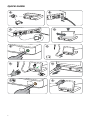
QUICK GUIDE
2

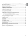
Contents Page
English (Instructions for use) ....................................................................................................... 4 -51
Български (Указания за ползване) .................................................................................... 52-105
Česky (Návod k použití) ..........................................................................................................106-155
Eλληvıĸά (δηγίες Xρήσεως) .................................................................................................... 156-211
Hrvatski (Upute za uporabu) .................................................................................................212-262
Magyar (Használati útmutató) .............................................................................................. 263-313
Polski (Instrukcja obsługi) .......................................................................................................314-365
Română (Instrucţiuni de utilizare) ...................................................................................... 366-417
Slovenčina (Návod na použitie) .......................................................................................... 418-467
Slovenšcina (Navodila za uporabo) ....................................................................................468-517
Türkçe (Kullanım talimatları) ..................................................................................................518-567
3

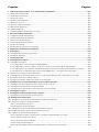
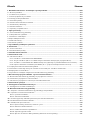
Content Page
1. Important Information – Read Before Use ........................................................................................ 6
1.1. Intended use .............................................................................................................................................................................6
1.2. Indications for use .................................................................................................................................................................6
1.3. Intended patient population ............................................................................................................................................6
1.4. Intended user profile ............................................................................................................................................................6
1.5. Clinical benefits ......................................................................................................................................................................6
1.6. Potential adverse events .....................................................................................................................................................6
1.7. General notes ...........................................................................................................................................................................6
1.8. Contraindications...................................................................................................................................................................6
1.9. Warnings and cautions ........................................................................................................................................................6
2. Device Description ............................................................................................................................... 8
2.1. Displaying unit parts ............................................................................................................................................................. 8
2.2. Product compatibility ..........................................................................................................................................................8
2.3. Endoscope activation ..........................................................................................................................................................9
2.4. Description of components ............................................................................................................................................ 10
2.5. Spare parts ..............................................................................................................................................................................11
2.6. System overview ..................................................................................................................................................................11
3. Explanation of Symbols Used ........................................................................................................... 12
4. Getting Started ...................................................................................................................................13
4.1. First-time setup ....................................................................................................................................................................13
4.2. User profiles ..........................................................................................................................................................................14
5. General Settings ................................................................................................................................. 16
6. Network Setup .................................................................................................................................... 16
6.1. Wi-Fi setup ............................................................................................................................................................................. 16
6.1.1. Wi-Fi network with WPA/WPA2 authentication ............................................................................................17
6.1.2. Hidden Wi-Fi network (Wi-Fi not showing on the list of available Wi-Fi connections) ................17
6.1.3. Wi-Fi network with WPA2 Enterprise authentication (username and password required) ........17
6.1.4. Import network certificate for WPA2 (TLS -transport security layer) ...................................................17
6.2. LAN connection via Ethernet cable ............................................................................................................................ 18
6.3. Set up static IP address and/or DNS server for a Wi-Fi or LAN network ..................................................... 18
6.4. Disconnect from Wi-Fi network .................................................................................................................................... 18
6.5. Clear all network data from the displaying unit .....................................................................................................19
7. Setup Connection to PACS and Worklist ......................................................................................... 19
7.1. Set up the displaying unit for server connection ....................................................................................................19
7.2. Set up connection to PACS server .................................................................................................................................19
7.3. Set up connection to Worklist server .........................................................................................................................20
8. Output Setup ......................................................................................................................................21
9. Endoscope Buttons Configuration...................................................................................................22
9.1. Configure the endoscope buttons ...............................................................................................................................22
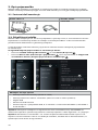
10. Operating the Displaying Unit .......................................................................................................22
10.1. Preparation and inspection of the displaying unit before use ...................................................................... 22
10.2. Starting and stopping a procedure .......................................................................................................................... 23
10.2.1. Starting a procedure ............................................................................................................................................. 23
10.2.2. Stopping a procedure .........................................................................................................................................23
10.3. Procedure workflow using the worklist .................................................................................................................. 23
10.4. Overview of Live View functions ................................................................................................................................ 24
10.5. Using image adjustments ............................................................................................................................................. 24
10.5.1. Adjust colour, contrast, sharpness and brightness ................................................................................... 25
10.5.2. Rotate the live image ............................................................................................................................................ 25
10.5.3. Use the zoom function ........................................................................................................................................25
10.5.4. Light on/off .............................................................................................................................................................. 26
10.5.5. Adjust ARC (Advanced Red Contrast) setting ............................................................................................. 26
4

en
5
10.6. Using the stopwatch ....................................................................................................................................................... 26
10.7. Using dual view .................................................................................................................................................................. 27
10.8. Taking photos and recording videos .......................................................................................................................27
10.9. Current procedure folder ............................................................................................................................................. 27
10.10. After use of the displaying unit ................................................................................................................................ 28
11. File Handling in The Archive ...........................................................................................................28
11.1. Accessing files in the Archive ....................................................................................................................................... 28
11.2. Exporting files to PACS server or USB flash drive ................................................................................................ 29
11.3. Deleting files from the Archive ................................................................................................................................... 31
12. Connect External Equipment .........................................................................................................32
12.1. Connecting to an External Monitor .......................................................................................................................... 32
12.2. Connecting USB Flash Drives....................................................................................................................................... 33
12.3. Connecting to an External Medical Imaging Recorder ................................................................................... 33
12.4. Printing images via external medical printer .......................................................................................................33
12.5. Connect external audio devices .................................................................................................................................34
12.5.1. Record sound during the procedure ..............................................................................................................34
12.5.2. Play sound recorded during a procedure ....................................................................................................34
13. System Information and Software Updates/Upgrades ...............................................................34
13.1. Device information page ............................................................................................................................................... 34
13.2. Software updates/upgrades ........................................................................................................................................ 34
13.3. Reporting a problem ....................................................................................................................................................... 35
13.4. Data reset ............................................................................................................................................................................. 35
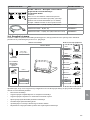
14. Cleaning and Disinfection of the Displaying Unit ....................................................................... 35
15. Maintenance .....................................................................................................................................37
16. Disposal .............................................................................................................................................37
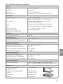
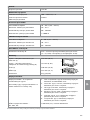
17. Technical Product Specifications ...................................................................................................37
17.1. Standards applied ............................................................................................................................................................. 37
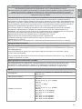
17.2. Specifications for the displaying unit ....................................................................................................................... 38
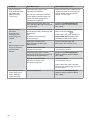
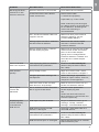
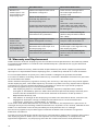
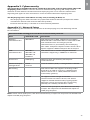
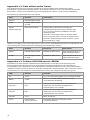
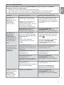
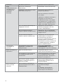
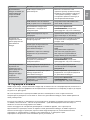
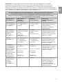
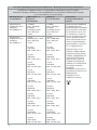
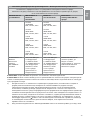
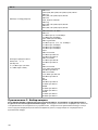
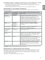
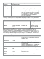
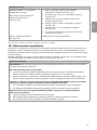
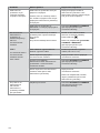
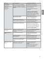
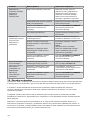
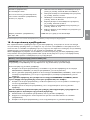
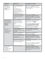
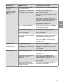
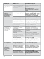
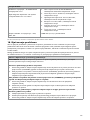
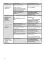
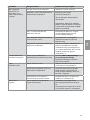
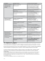
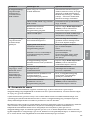
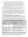
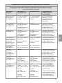
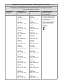
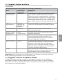
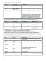
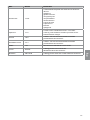
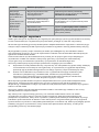
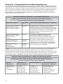
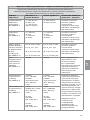
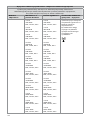
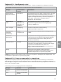
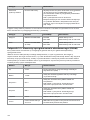
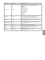
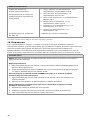
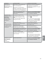
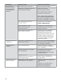
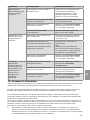
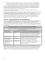
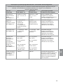
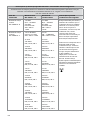
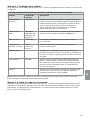
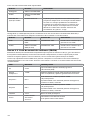
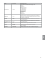
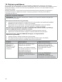
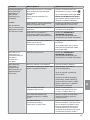
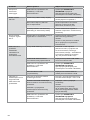
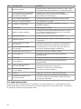
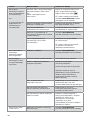
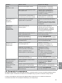
18. Troubleshooting ...............................................................................................................................39
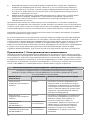
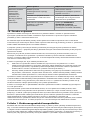
19. Warranty and Replacement ............................................................................................................42
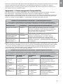
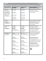
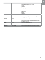
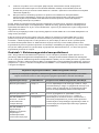
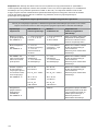
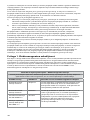
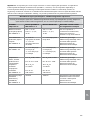
Appendix 1. Electromagnetic Compatibility ..................................................................................... 43
Appendix 2. Radio Frequency Compliance .........................................................................................46
Appendix 3. Cybersecurity ....................................................................................................................49
Appendix 3.1. Network Setup ................................................................................................................................................ 49
Appendix 3.2. Data at Rest and In Transit ......................................................................................................................... 50
Appendix 3.3. Software Bill Of Materials (SBOM) ........................................................................................................... 50

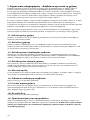
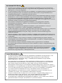
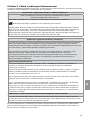
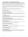
1. Important Information – Read Before Use
Read these Instructions for Use carefully before using the Ambu® aBox™ 2. These Instructions for
Use may be updated without further notice. Copies of the current version are available upon
request. The latest version is available on ambu.com. Please be aware that the instructions do
not explain or discuss clinical procedures. They describe only the basic operation and
precautions related to the operation of the Ambu® aBox™ 2.
In these Instructions for Use, the term displaying unit refers to Ambu® aBox™ 2. The terms
visualization device and endoscope are used interchangeably throughout the document and
refer to compatible Ambu endoscopes and other visualization devices that can be connected
to and used with the displaying unit.
These Instructions for Use apply only to the displaying unit. For information on a specific Ambu
visualization device, refer to the relevant Instructions for Use
1.1. Intended use
The aBox™ 2 is intended to display live imaging data from compatible Ambu visualization devices.
1.2. Indications for use
As the aBox™ 2 is intended to display live imaging data from compatible Ambu visualization
devices, the intended medical indication will be defined by the connected visualization devices.
1.3. Intended patient population
As the displaying unit is intended to display live imaging data from specific Ambu
visualization devices, the intended patient population will be defined by the connected
Ambu visualization devices.
1.4. Intended user profile
Healthcare professionals trained on procedures with compatible visualization devices typically
assisted by other healthcare professionals and medical technicians with knowledge of setting
up medical devices.
1.5. Clinical benefits
In conjunction with a compatible single-use visualization device, the Ambu® aBox™ 2 provides
visualization and inspection of hollow organs and cavities in the body.
1.6. Potential adverse events
None known for the displaying unit.
1.7. General notes
If, during the use of this device or as a result of its use, a serious incident has occurred, please
report it to the manufacturer and to your national authority.
1.8. Contraindications
None known for the displaying unit.
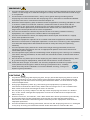
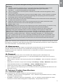
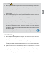
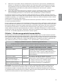
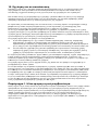
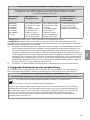
1.9. Warnings and cautions
Failure to observe these warnings and cautions may result in patient injury or damage to the
equipment. Ambu is not responsible for any damage to the equipment or patient injury
resulting from incorrect use.
6

en
7
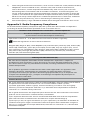
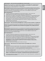
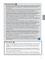
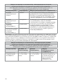
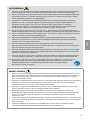
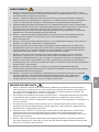
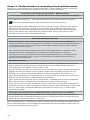
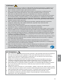
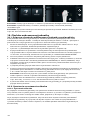
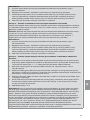
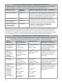
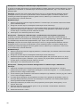
WARNINGS
1. To avoid patient injury during procedure, be careful to check whether the image on the
screen is a live image or a recorded image and verify that the orientation of the image
is as expected.
2. To minimize risk of contamination, always wear gloves during handling of the
displaying unit and ensure that the displaying unit is cleaned and disinfected before
and after each use in accordance with the chapter 14.
3. Portable radio frequency (RF) communications equipment (including peripherals such
as antenna cables and external antennas) should be used no closer than 30 cm
(12inches) to any part of the displaying unit and the attached visualization device,
including cables specified by the manufacturer. Otherwise, this could result in
degradation of the performance of this equipment.
4. To avoid risk of electric shock only connect mains or battery powered ancillary
equipment, if it is approved as medical electrical equipment.
5. To avoid risk of electric shock, this equipment shall only be connected to a supply
mains with protective earth.
6. Use of this equipment adjacent to or stacked with other equipment should be avoided
because it could result in improper operation. If such use is necessary, this equipment
and the other equipment should be observed to verify that they are operating
normally.
7. To avoid patient injury due to loss of the live image during procedure, ensure to
correctly connect the power cord to an appropriate power source that will ensure
continuous power supply.
8. To avoid patient injury due to overheating of the displaying unit causing it to suddenly
shut down during procedure, do not cover the ventilation holes at the bottom of the
displaying unit.
9. Do not touch any metal parts of the displaying unit while using high frequency tools
(e.g. electrosurgical equipment), due to the risk of electric shock and burns.
10. To ensure that images and videos are correctly exported to external systems and to
avoid potential misdiagnosis due to mixing-up of patient data, carefully
check that the patient identifiers are correct before starting, saving and
exporting the procedure.
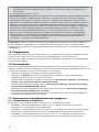
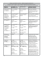
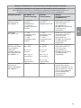
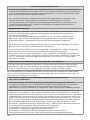
CAUTIONS
1. To prevent damaging the displaying unit, always place the displaying unit on a hard
flat surface during use to avoid covering the ventilation holes at the bottom of the
displaying unit. Be aware that covering the ventilation holes can also lead to a high
surface temperature.
2. Using high frequency tools (e.g. electrosurgical equipment) in proximity of a
connected visualization device may affect the live image. This is not a malfunction.
Wait a few seconds for the image to return to normal.
3. Do not place any heavy objects on the top of the displaying unit when it is folded
flat, as this could damage the equipment and lead to malfunction or exposure of
electrical parts.
4. Use of accessories, transducers, and cables other than those specified or provided by
the manufacturer of this equipment could result in increased electromagnetic
emissions or decreased electromagnetic immunity of this equipment and result in
improper operation.
5. To avoid malfunction during procedure, do not use the displaying unit if it is damaged
in any way or if any part of the functional check described in section 10.1 fails.

6. To avoid malfunction of the equipment only use spare parts supplied by Ambu.
Do not modify the spare parts.
7. Cleaning and disinfection wipes shall be moist, but not dripping to ensure no damage
to internal electronics of the displaying unit.
8. If using wipes containing hypochlorite or citric acid during cleaning, ensure that all
residue is completely removed. Wipes containing hypochlorite or citric acid may affect
the screen's antireflective coating over time. You should limit the use of wipes
containing hypochlorite or citric acid to required cases only.
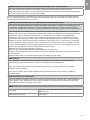
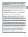
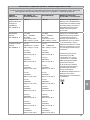
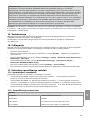
2. Device Description
The displaying unit can be connected to compatible Ambu visualization devices to display
video images. The following sections describe the components of the displaying unit and list
compatible devices.
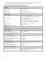
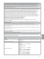
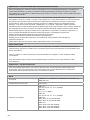
2.1. Displaying unit parts
Ambu® aBox™ 2 Item number
505001000
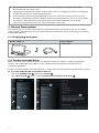
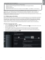
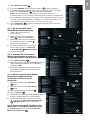
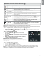
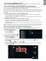
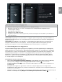
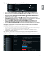
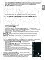
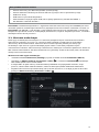
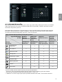
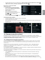
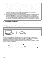
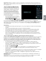
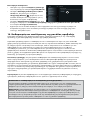
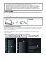
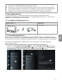
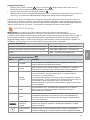
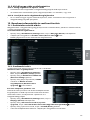
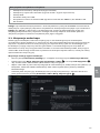
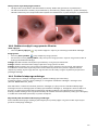
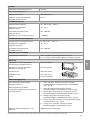
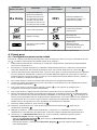
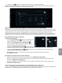
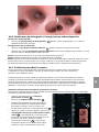
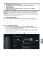
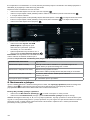
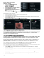
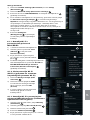
2.2. Product compatibility
aBox 2 includes two connector ports on the front marked in colours. Ambu visualization
devices are compatible with aBox 2 at the colour-coded connection mechanism and
connector geometry.
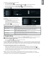
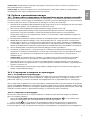
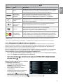
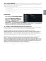
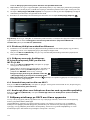
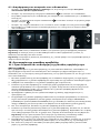
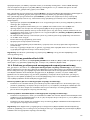
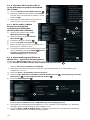
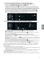
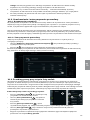
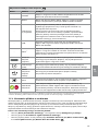
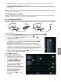
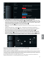
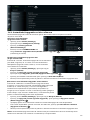
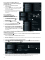
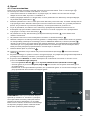
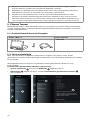
A full list of compatible visualization devices is displayed in the user interface of the displaying unit.
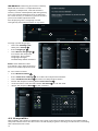
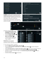
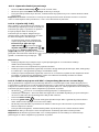
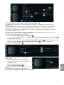
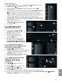
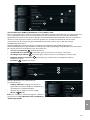
To see compatible Ambu visualization devices:
•Press the Settings tab 1, then press About 2.
•Press Device info 3, then scroll to Supported visualization devices 4.
1
2
3
4
8

en
9
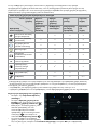
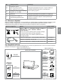
Compatible external equipment
•External medical grade monitors (video output)
•External medical imaging recorders (video output and trigger output)
•USB flash drives
•Medical USB printer
•USB powered audio devices that comply with IEC 60601-1, IEC 60950-1 or IEC 62368-1
Note: Verified compatibility with Sony UP-DR80MD digital colour printer for medical
applications. For specifications of connections to external equipment, refer to chapter 12.
Note: IEC 60950-1 and IEC 62368-1 are consumer electronic standards and do not cover
patient safety. Therefore do not touch the accessories while touching the patient and place the
equipment out of reach of the patient.
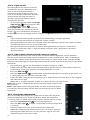
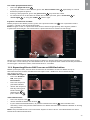
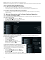
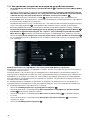
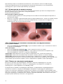
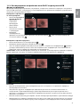
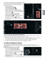
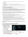
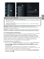
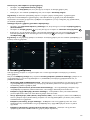
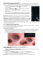
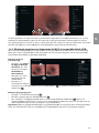
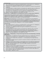
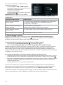
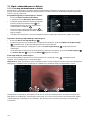
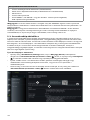
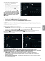
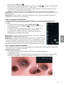
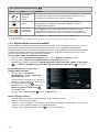
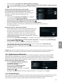
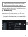
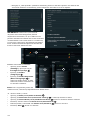
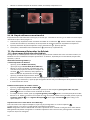
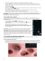
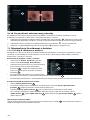
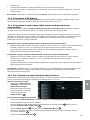
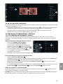
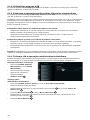
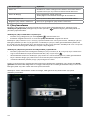
2.3. Endoscope activation
New endoscope types that are not found on the displaying unit's list of supported endoscopes
(see section 2.2) must be activated with an activation code before they can be used with the
displaying unit. The activation code is entered only once for each endoscope type, and once
an endoscope type has been activated, it can be found on the list of supported visualization
devices. The activation codes are found on Ambu's website via the URL shown on the
displaying unit's screen next to the input field where the activation code is to be entered.
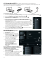
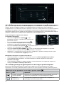
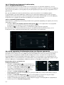
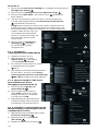
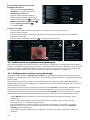
Activate a new endoscope type:
•Press the Settings tab, then press About.
•Scroll to Activation codes 5 and press the question mark 6 to find the URL or QR code
for the activation codes.
•Enter the URL in the address field of the internet browser on your connected device,
e.g. computer, tablet or mobile phone or scan the QR code with your mobile phone.
•Find the activation code for the endoscope to be activated and enter the code into the
input field below Activation codes 7.
5
6
7

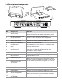
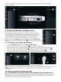
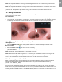
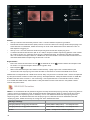
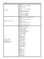
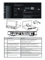
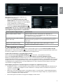
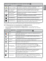
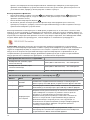
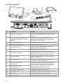
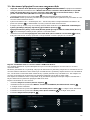
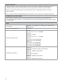
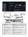
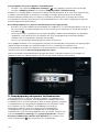
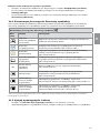
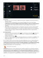
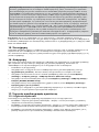
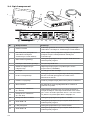
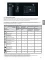
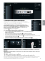
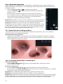
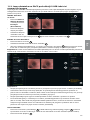
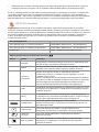
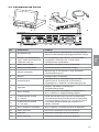
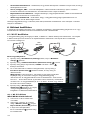
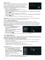
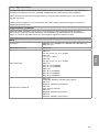
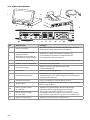
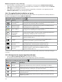
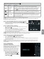
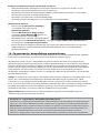
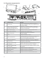
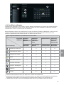
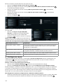
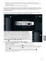
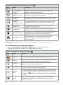
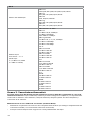
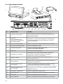
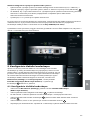
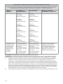
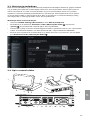
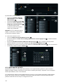
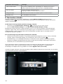
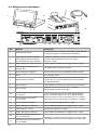
2.4. Description of components
1
3
2
4
Wi-Fi
1
2345
10 11 12 13 14 15 16 17 18 19
6
7
8
9
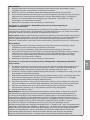
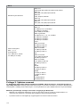
No. Component Function
1Touch screen Displays the graphical user interface and shows
the live image from the Ambu visualization device.
2
VDI port (connector port
for specific Ambu
visualization devices)
Connector port geometry and colour
ensures correct connection with compatible
visualization devices.
3USB 3.0 port (front) Enables connection of external USB flash drives.
4USB port cover (front) Protects the front USB port.
5Power button Turns the power ON or switches to STANDBY mode.
6Base Contains the main unit.
7Positioning arm
Enables manual positioning of the touch screen.
The screen can be adjusted horizontally and
vertically as well as rotated.
8Power cable Connects the displaying unit to a power outlet.
9Wi-Fi antenna Connect Wi-Fi antenna to the displaying unit for
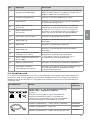
improved Wi-Fi signal.
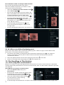
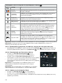
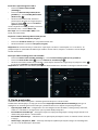
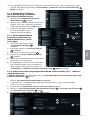
10 Video output ports
(2x DVI-D) Enable connection to external monitor or external
medical imaging recorder. See section 7.1. for details
on the difference between using DVI-D and 3G-SDI
on the displaying unit.
11 Video output ports
(2x 3G-SDI)
12 Wi-Fi antenna connector Enables connection of Wi-Fi antenna.
13 USB 3.0 ports Enables connection of external USB flash drives.
14 LAN port Enables connection to ethernet.
15 USB 2.0 ports Enables connection of external USB flash drives.
16 Trigger output ports
(2 x 3.5 mm jack) Enable connection to an external medical imaging
recorder to transfer trigger signals.
17 Trigger output ports
(2 x D-SUB9)
10

en
11
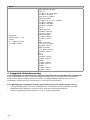
No. Component Function
18 Power inlet Enables connection to power cable.
19 Connector for potential
equalization cable
Enables bonding of electrical products to eliminate
potential differences between conductive parts.
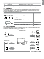
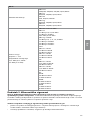
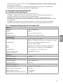
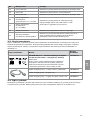
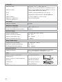
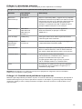
2.5. Spare parts
Spare parts are intended as replacements for components that are exposed to wear and tear
during the lifetime of the device. Consult the troubleshooting guide in chapter 13 for issues
that might require replacement of spare parts.
Spare parts Name Item number
Thickness: 4 pt
Ambu® aBox™ 2 -Visualization device
interface kit - Grey-Empty-Green
Contains:
One grey and one green visualization device
interface board (VDI), a front cover with a color
ring (grey and green), a plectrum tool, and two
screws for the VDI.
505000530
Power cable – B (US, JP) 505000521
Power cables – J (CH), K (DK), I (AUS) 505000520
Power cable – G (UK), E/F (EU, not DK, CH) 505000522
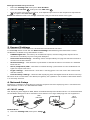
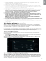
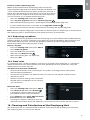
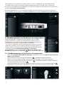
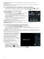
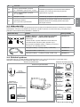
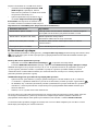
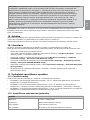
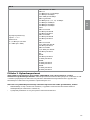
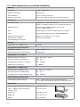
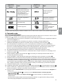
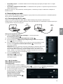
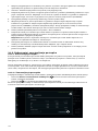
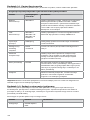
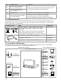
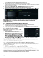
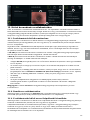
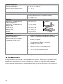
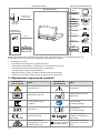
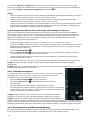
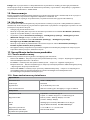
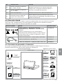
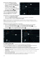
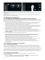
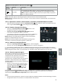
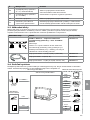
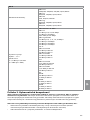
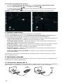
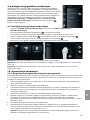
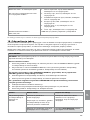
2.6. System overview
A complete Ambu Imaging System is configured as illustrated in the figure below. The various
connections are described in more detail in chapter 12.
DVI-D
3G-SDI
DVI-D
USB 2.0/3.0
USB 3.0 Type A
USB 3.0 Type A
DICOM
USB Flash Drive
Server
Wi-Fi
LAN
PACS Server/
Worklist Server
Medical Printer
Audio Device
External Monitor
External Medical
Imaging Recorder
Visualization
Device
Image and Video
Streams
USB 3.0
Ambu Displaying Unit
External Connection OptionsAmbu Imaging System
Software
Update/Upgrade
Wi-Fi
LAN
Recordings/
Log Files
3G-SDI
3.5 mm Jack
D-SUB9

Please note that your organization is responsible for the following areas, which should be
implemented according to your local policy:
•Network setup
•Ensuring availability and confidentiality of the network
•Ensuring confidentiality and integrity of physical devices
•Management of the displaying unit user profiles
•Maintenance of user passwords
•Monitoring and audit of the Ambu imaging system
•Complete data erasure before disposal of the displaying unit
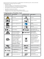
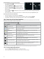
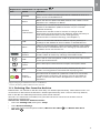
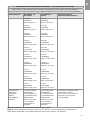
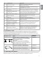
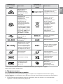
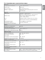
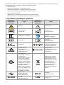
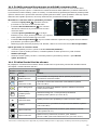
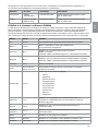
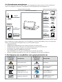
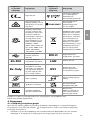
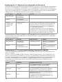
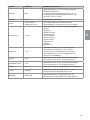
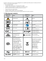
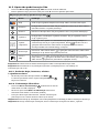
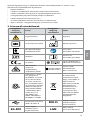
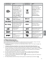
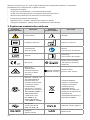
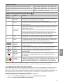
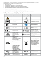
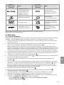
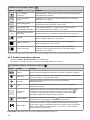
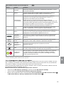
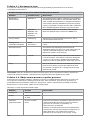
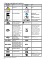
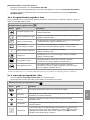
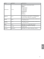
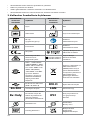
3. Explanation of Symbols Used
Symbols for the
displaying unit Description Symbols for the
displaying unit Description
Warning Caution
Medical Device Made in Taiwan
Type BF applied part Follow
Instructions for Use
Batch Code Consult
Instructions for Use
CE marking Japan Radio Law
TELEC RF certification
Australia and New
Zealand’s Regulatory
Compliance Mark
Taiwan Radio
Requirement
NCC certification
E354633
Medical – general
medical equipment as
to electrical shock, fire
and mechanical hazards
only in accordance
with ANSI/AAMI
ES60601-1:2005/
AMD2:2021+CAN/CSA-
C22.2 NO. 60601-1:14/
AMD2:2022(MOD)+
IEC 60601-2-18:2009
Waste Bin symbol,
indicating that waste
must be collected
according to local
regulation and
collection schemes for
disposal of electronic
and electrical waste
(WEEE)
Universal Serial Bus
(USB 2.0, USB 3.0) DVI-D Digital Visual Interface
3G-SDI Serial Digital Interface LAN Local Area Network
Rx Only
US Federal Law
restricts this device to
sale by or on the order
of a physician
IP31 Protection against
solid particles and
liquid ingress
Humidity Limitation Atmospheric
Pressure Limitation
12

en
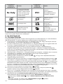
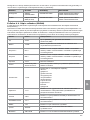
13
Symbols for the
displaying unit Description Symbols for the
displaying unit Description
Catalogue Number UK Conformity
Assessed
UK Responsible Person
Importer
(For products imported
into Great Britain only)
A full list of symbol explanations can be found on ambu.com/symbol-explanation.
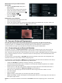
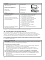
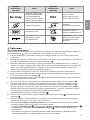
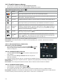
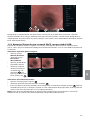
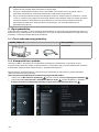
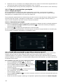
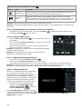
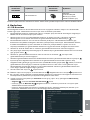
4. Getting Started
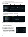
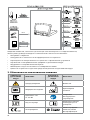
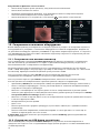
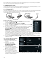
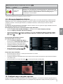
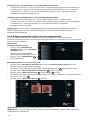
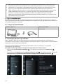
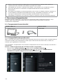
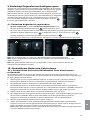
4.1. First-time setup
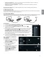
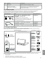
Follow the steps below before using the displaying unit for the first time. Letters in grey circles
refer to the illustrations in the Quick Guide on page 2.
1. Unpack the displaying unit and verify that no parts are missing. Refer to the parts
described in section 2.4.
2. Closely examine the displaying unit and other parts for any damage. Do not use the
displaying unit if it is damaged in any way A.
3. Place the displaying unit on a hard and leveled surface. Be aware to place the displaying
unit in a position where the power cord is accessible. The displaying unit can be placed on
a medical cart to make it moveable. Make sure to proper position of the displaying unit to
avoid falling down during transportation.
4. If necessary, connect the supplied Wi-Fi antenna to the back of the displaying unit.
5. Connect the power cable to a power outlet and insert the power plug into the power inlet
on the back of the displaying unit B.
6. If needed, connect an external monitor C and/or medical imaging recorder to the back of
the displaying unit.
7. If necessary, manually adjust the orientation of the touch screen of the displaying unit D
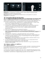
8. Turn ON the displaying unit by short pressing the power button. The indicator light in the
power button switches from orange (STANDBY mode) to green (ON) E, but a live image is
available soon after the monitor is turned on if a visualization device is connected. If no
visualization device is connected, the interface will illustrate how to correctly connect
a visualization device to the displaying unit.
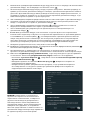
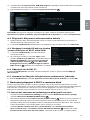
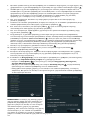
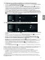
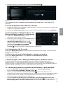
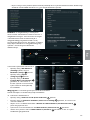
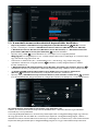
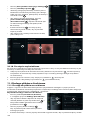
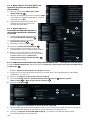
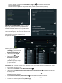
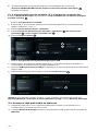
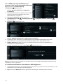
9. Select the preferred language, then press 1.
10. Select and confirm your country, then press Continue 2. Press confirm 3.
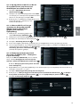
11. Go to Appendix 3. Cybersecurity and ensure that the use of the displaying unit's software
and connectivity is aligned with your organization's policies.
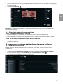
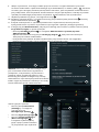
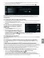
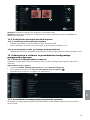
12. Log in as Administrator to get access to system settings: Press the Login tab
in the Toolbar.
– Press arrow right 4 , then press System Administrator 5.
– Enter the password and press Log in 6. The factory default password is AmbuAdmin
– Navigate to User profiles to change the Password. For security reasons you should
change the factory default password as soon as possible.
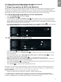
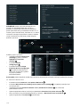
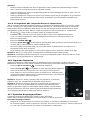
12

IMPORTANT!: Selecting the correct country
from the first time is a requirement for
regulatory compliance, and the selected
country cannot subsequently be changed by
any users of the displaying unit. If selection
of a new country is necessary, please contact
your local Ambu representative.
The displaying unit’s language can be
changed by the Administrator at any time.
4
5
6
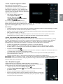
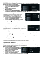
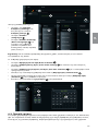
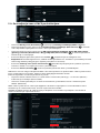
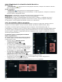
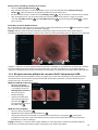
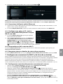
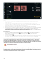
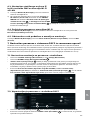
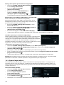
Change system language:
• Press the Settings tab,
then press Setup 7.
•Press Language 8.
•Press Device language 9,
and select the required
language. The system
language changes
immediately when selected.
Note: If the Administrator
password is lost, please contact
your local Ambu representative.
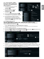
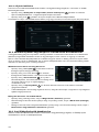
13. Set date and time:
•Press Date and time 10 .
•Press Time zone setting 11 , and select the required time zone.
•Press Set date and time 10 to return to the previous menu.
•Select the required setting below Time format 12 .
•Scroll the hours and minutes below Set time 13 to set the time.
•Select the required date 14 in the calendar.
11
10
12
14
13
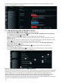
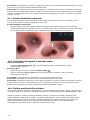
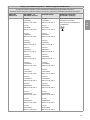
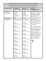
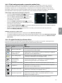
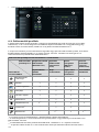
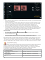
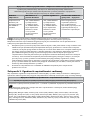
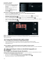
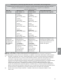
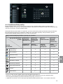
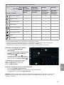
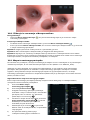
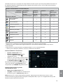
4.2. User profiles
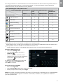
User profiles are created as different user types according to their purpose (see table below).
Only the Administrator has full access to the displaying unit's settings and functions, including
the creation of new users.
3
78
9
14

en
15
For daily operation it is recommended to create minimum one Advanced user profile, either as
a shared department login or as individual profiles. It is not possible to create additional
Administrator or Service Technician user profiles.
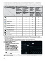
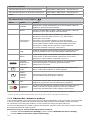
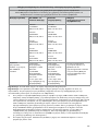
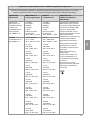
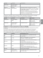
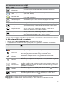
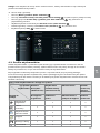
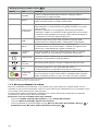
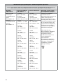
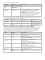
User profile types and system access
User profile type
Function access
Default user Advanced
user
Administrator Service
Technician
Access
without login
Daily
operation
Administrator
with full access
Service
related tasks
Login required -x x x
Live View x x x x
Video recording x x x x
Photo x x x x
Current procedure x x x x
Worklist -*x x -*
+ARC Image adjustments x** x** x x
Archive*** -*x x -*
Settings - x**** x x****
* The Administrator can enable or disable access without login.
** The Administrator and the Service Technician can enable or disable functions for other users.
*** User profiles access to the Bin is described in section 11.3.
**** Some settings are not accessible for the Advance user and the Service Technician.
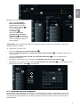
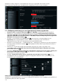
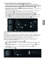
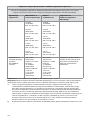
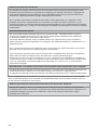
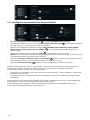
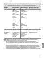
Create an Advanced user:
•Press the Settings tab.
•Press User Profiles, then press
Add user 5.
•Enter username, password, and
repeated password in the respective
input fields 6, and press the
Save icon 7.
To delete a user profile, press the user
name, then press the delete icon.
Press OK to confirm.
Log in as any user profile:
•Press the Login tab.
•Press arrow right, then press your user name.
•Enter your password and press Login.
Note: Passwords must be minimum 8 characters. Any character is allowed, but it is recommended
to use a combination of upper- and lower-case letters, numbers, and symbols to enhance
password protection.
7
6
5

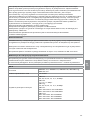
Change username or password:
•Press the Settings tab, then press User Profiles.
•Press the username 8, then press the edit icon 9.
•Enter the new username, password, and repeated password in the respective input fields
10 and press the save icon 11 .
Note: The Administrator can change username and password for other user types.
11
10
8
9
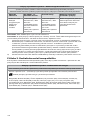
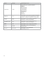
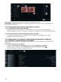
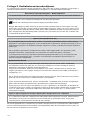
5. General Settings
The Administrator can enable and disable functionalities for all users.
In the Setup menu under the tab General Settings the following functionalities can be
enabled or disabled using the ON/OFF sliders:
•USB Management – Possibility to enable file export, software upgrade, import of TLS
certificate and ability to print using the USB port.
•Communication Settings – Enabling allows the possibility to upgrade software online if
connected to the internet.
•Archive Settings – Decide when a procedure is moved to the bin and when it is deleted
from the bin.
•Zoom, Stopwatch, ARC – functions available during a procedure can be disabled for all
types of scopes and users.
•Login Settings – determine if a user that is not logged in can still access the archive and
see the worklist.
•User inactivity settings – choose if the displaying unit will logout the user due to inactivity.
Be aware that if a function is disabled (not green), the symbol is not visible in the menu where
it is normally located.
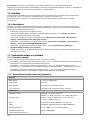
6. Network Setup
Importing a worklist or transferring imagery requires that the displaying unit is connected to
the network via Wi-Fi or LAN/Ethernet cable.
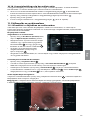
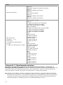
6.1. Wi-Fi setup
The displaying unit supports WPA, WPA2 and WPA2 Enterprise authentication. It is recommended
to use WPA2 Enterprise. Wi-Fi networks that redirect to a login webpage are not supported.
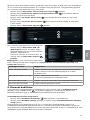
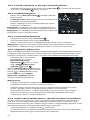
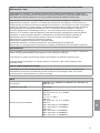
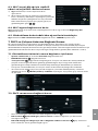
Enable Wi-Fi:
1) Press the Settings tab, then press Setup 1.
16

en
17
2) Press Network setup 2.
3) Press the ON/OFF slider to turn on Wi-Fi 3 (switch to green).
4) If required by your organization’s Wi-Fi network, press the input
field next to Hostname 4 and enter the hostname.
Note: The hostname is provided by your organization's IT
administrator and is used for identifying the displaying unit on the
Wi-Fi network. The hostname can be 1-63 characters long excl. dots
and can consist of numbers and upper- or lowercase letters (A-Z/
a-z). Hyphens cannot be used as first or last character.
5) Press Configure 5 and wait while the displaying unit searches
for available networks.
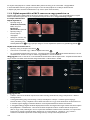
6.1.1. Wi-Fi network with
WPA/WPA2 authentication
1) Select the Wi-Fi network
from the list.
2) Enter the password and press
Save 6, then press Connect.
3) When the connection has been
established, a Wi-Fi symbol
appears in the Toolbar.
4) To enable automatic connection
to this Wi-Fi press the Connect
automatically 7 ON/OFF slider
(switch to green).
6.1.2. Hidden Wi-Fi network
(Wi-Fi not showing on the list
of available Wi-Fi connections)
1) Press Add network 8.
2) Press the input field next to SSID and enter
the name of the hidden Wi-Fi network,
then press OK.
3) Enter the remaining information in the
input fields depending on the type of
Wi-Fi network.
6.1.3. Wi-Fi network with WPA2
Enterprise authentication
(username and password
required)
1) Enter username in the Identity
9 field.
2) Enter password in the Password
10 field.
3) Select the required certificate 11 .
4) Press Connect 12 .
5) When the connection has been established,
a Wi-Fi symbol appears in the Toolbar.
6) To enable automatic connection to this
Wi-Fi, press the Connect automatically
13 ON/OFF slider (switch to green).
6.1.4. Import network certificate for
WPA2 (TLS -transport security layer)
In the Network menu, scroll to Imported
Network certificates 14 .
1
6
7
4
2
5
3
8
9
10 11
12
13
14

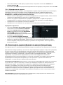
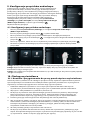
6.1.4.1. Import TLS certificates from a server
1) Ensure that the displaying unit is connected to a temporary Wi-Fi or LAN network
(see section 5.1.1 or 5.2.).
2) Press Server import.
3) Enter Certificate file name 15 , Host name 16 , and Port number 17 .
4) Press Import 18 .
15
16
17
18
6.1.4.2. Import network certificates from a USB flash drive
1) Ensure that USB connection has been enabled for certificate import (see section 2.5.).
Insert USB containing network certificate. (see section 6.1.4).
2) Press USB import and wait while the displaying unit searches for network certificates on
the USB flash drive.
3) Select the required network certificate and press Import 19 .
19
Note: When the network certificate has been imported, the name of the certificate file is
shown below Imported Network certificates in the Network menu.
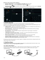
6.2. LAN connection via Ethernet cable
1) Connect a LAN cable to the Ethernet connection port on the back of the displaying unit
and to a router or LAN wall socket.
2) In the Network menu, check the LAN connection status shown below Ethernet.
6.3. Set up static IP address and/or
DNS server for a Wi-Fi or LAN network
1) In the Network menu, press the currently
selected Wi-Fi network.
2) Below the name of the Wi-Fi network, press the
arrow next to IP address. Press the ON/OFF
slider next to Enable static IP 20 or Configure
manual DNS servers 21 (switch to green) and
enter the required information.
6.4. Disconnect from Wi-Fi network
In the Network menu, press the currently selected. Wi-Fi network, then press Disconnect.
20
21
18

en
19
6.5. Clear all network data from the displaying unit
In the Network menu, press Clear all data. Press OK.
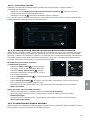
7. Setup Connection to PACS and Worklist
Importing a worklist and exporting of imagery requires that the worklist server/PACS (Picture
Archiving and Communication System) server can send and receive data in DICOM (Digital
Imaging and Communications in Medicine) format. Setting up server connections require that
the displaying unit is connected to a Wi-Fi or LAN network (see section 6.1 and 6.2).
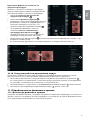
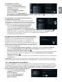
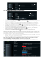
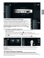
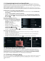
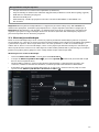
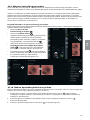
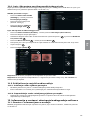
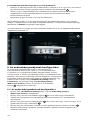
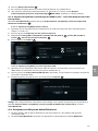
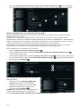
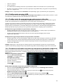
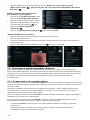
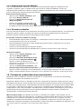
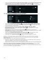
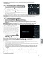
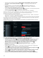
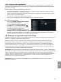
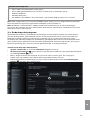
7.1. Set up the displaying unit for server connection
•Press the Settings tab, then press Setup.
•Press DICOM setup 22 .
•It is optional to change the Station name 23 . The Station name is used to recognize the
unit if a special worklist needs to be pushed to a specific unit or if it is important to track
from which unit data has been sent from. The default name is AmbuMon and the maximum
length of the station name is 16 characters.
•Press Use serial number or Use custom name next to Station AE title 24 . If you selected
Use custom name, press the input field and enter the name.
22 25
24
23
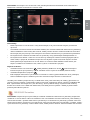
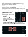
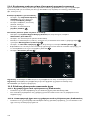
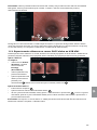
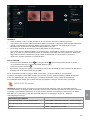
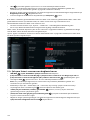
7.2. Set up connection to PACS server
26
27
28
29
30
•Press Add new 25 below PACS servers.
•Press the input field next to PACS name 26 and enter the name you want to use for the
PACS connection.
•Press the input fields next to PACS AE title, Host name and Port number 27 and enter
the required information in each field.
•Press the required setting next to TLS 28 . It is recommended to enable TLS.
Note: If you enable TLS, you need to import the required TLS certificate from a server or
USB flash drive (see instructions further below).
•Press Test connection 29 to verify that the information has been entered correctly and
the server connection can be established.
•Press Create 30 to save the server connection setup.
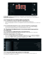
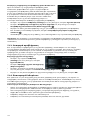
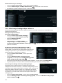
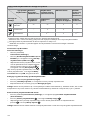
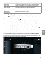
Some PACS systems may require the MAC address and the IP address of the displaying unit.
The MAC address is unique for each displaying unit, while the IP address is assigned by the
hospital network.
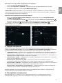
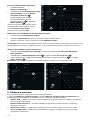
Retrieve the MAC address and IP address of the displaying unit:
•Login as Administrator, then go to Settings - About - Device Info.
•Depending on whether Wi-Fi or Ethernet is used, find the information tab Network.
The MAC address is a 48-bit address grouped into 6 octets. In the example below, the MAC
address is highlighted in red boxes depending on the network setup.

The IP address assigned by your network can also be found. In the example below, the IP
address is highlighted in a blue box.
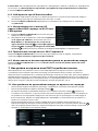
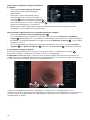
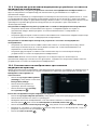
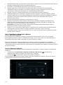
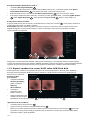
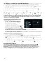
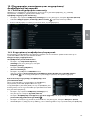
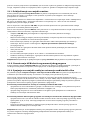
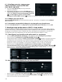
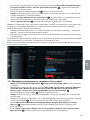
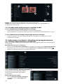
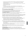
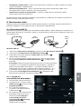
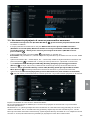
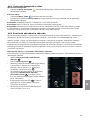
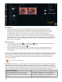
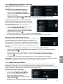
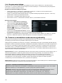
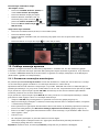
7.3. Set up connection to Worklist server
•Enable Worklist 31 with the ON/OFF switched to green.
•Enter the required information in Worklist server AE title, Worklist server hostname
and Worklist server port number 32 .
•Press the required TLS 33 settings. It is recommended to enable TLS.
Note: If you enable TLS, you need to import the required TLS certificate from a server or
USB flash drive.
•Choose the modality (ES=endoscopy, US=ultrasound) or enter a specific modality in the
Other 34 field deciding which worklist you choose to retrieve.
•Enter the timeframe, that the retrieved worklist will show, in the Display upcoming
procedures (hours) 35 field.
•Hide past procedures older than (hours) 36 allows you to limit the amount of
procedures in the worklist.
•Press Test worklist connection 37 to verify that the information has been entered
correctly and the server connection is established.
31
37
35
32
33
36
34
38
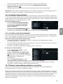
Import TLS certificate from server or USB flash drive:
You can use TLS for enhanced security when setting up PACS and Worklist server connections.
Enabling TLS requires a TLS certificate to be imported to the displaying unit from a server or
from a USB flash drive. If multiple TLS certificates are imported to the displaying unit,
the PACS/Worklist server will select the required TLS certificate automatically. For import
from server, ensure that the displaying unit is connected to a Wi-Fi or LAN network.
For import from USB flash drive, ensure that USB connection has been enabled for certificate
import and a USB flash drive connected to the displaying unit.
20
Sayfa yükleniyor...
Sayfa yükleniyor...
Sayfa yükleniyor...
Sayfa yükleniyor...
Sayfa yükleniyor...
Sayfa yükleniyor...
Sayfa yükleniyor...
Sayfa yükleniyor...
Sayfa yükleniyor...
Sayfa yükleniyor...
Sayfa yükleniyor...
Sayfa yükleniyor...
Sayfa yükleniyor...
Sayfa yükleniyor...
Sayfa yükleniyor...
Sayfa yükleniyor...
Sayfa yükleniyor...
Sayfa yükleniyor...
Sayfa yükleniyor...
Sayfa yükleniyor...
Sayfa yükleniyor...
Sayfa yükleniyor...
Sayfa yükleniyor...
Sayfa yükleniyor...
Sayfa yükleniyor...
Sayfa yükleniyor...
Sayfa yükleniyor...
Sayfa yükleniyor...
Sayfa yükleniyor...
Sayfa yükleniyor...
Sayfa yükleniyor...
Sayfa yükleniyor...
Sayfa yükleniyor...
Sayfa yükleniyor...
Sayfa yükleniyor...
Sayfa yükleniyor...
Sayfa yükleniyor...
Sayfa yükleniyor...
Sayfa yükleniyor...
Sayfa yükleniyor...
Sayfa yükleniyor...
Sayfa yükleniyor...
Sayfa yükleniyor...
Sayfa yükleniyor...
Sayfa yükleniyor...
Sayfa yükleniyor...
Sayfa yükleniyor...
Sayfa yükleniyor...
Sayfa yükleniyor...
Sayfa yükleniyor...
Sayfa yükleniyor...
Sayfa yükleniyor...
Sayfa yükleniyor...
Sayfa yükleniyor...
Sayfa yükleniyor...
Sayfa yükleniyor...
Sayfa yükleniyor...
Sayfa yükleniyor...
Sayfa yükleniyor...
Sayfa yükleniyor...
Sayfa yükleniyor...
Sayfa yükleniyor...
Sayfa yükleniyor...
Sayfa yükleniyor...
Sayfa yükleniyor...
Sayfa yükleniyor...
Sayfa yükleniyor...
Sayfa yükleniyor...
Sayfa yükleniyor...
Sayfa yükleniyor...
Sayfa yükleniyor...
Sayfa yükleniyor...
Sayfa yükleniyor...
Sayfa yükleniyor...
Sayfa yükleniyor...
Sayfa yükleniyor...
Sayfa yükleniyor...
Sayfa yükleniyor...
Sayfa yükleniyor...
Sayfa yükleniyor...
Sayfa yükleniyor...
Sayfa yükleniyor...
Sayfa yükleniyor...
Sayfa yükleniyor...
Sayfa yükleniyor...
Sayfa yükleniyor...
Sayfa yükleniyor...
Sayfa yükleniyor...
Sayfa yükleniyor...
Sayfa yükleniyor...
Sayfa yükleniyor...
Sayfa yükleniyor...
Sayfa yükleniyor...
Sayfa yükleniyor...
Sayfa yükleniyor...
Sayfa yükleniyor...
Sayfa yükleniyor...
Sayfa yükleniyor...
Sayfa yükleniyor...
Sayfa yükleniyor...
Sayfa yükleniyor...
Sayfa yükleniyor...
Sayfa yükleniyor...
Sayfa yükleniyor...
Sayfa yükleniyor...
Sayfa yükleniyor...
Sayfa yükleniyor...
Sayfa yükleniyor...
Sayfa yükleniyor...
Sayfa yükleniyor...
Sayfa yükleniyor...
Sayfa yükleniyor...
Sayfa yükleniyor...
Sayfa yükleniyor...
Sayfa yükleniyor...
Sayfa yükleniyor...
Sayfa yükleniyor...
Sayfa yükleniyor...
Sayfa yükleniyor...
Sayfa yükleniyor...
Sayfa yükleniyor...
Sayfa yükleniyor...
Sayfa yükleniyor...
Sayfa yükleniyor...
Sayfa yükleniyor...
Sayfa yükleniyor...
Sayfa yükleniyor...
Sayfa yükleniyor...
Sayfa yükleniyor...
Sayfa yükleniyor...
Sayfa yükleniyor...
Sayfa yükleniyor...
Sayfa yükleniyor...
Sayfa yükleniyor...
Sayfa yükleniyor...
Sayfa yükleniyor...
Sayfa yükleniyor...
Sayfa yükleniyor...
Sayfa yükleniyor...
Sayfa yükleniyor...
Sayfa yükleniyor...
Sayfa yükleniyor...
Sayfa yükleniyor...
Sayfa yükleniyor...
Sayfa yükleniyor...
Sayfa yükleniyor...
Sayfa yükleniyor...
Sayfa yükleniyor...
Sayfa yükleniyor...
Sayfa yükleniyor...
Sayfa yükleniyor...
Sayfa yükleniyor...
Sayfa yükleniyor...
Sayfa yükleniyor...
Sayfa yükleniyor...
Sayfa yükleniyor...
Sayfa yükleniyor...
Sayfa yükleniyor...
Sayfa yükleniyor...
Sayfa yükleniyor...
Sayfa yükleniyor...
Sayfa yükleniyor...
Sayfa yükleniyor...
Sayfa yükleniyor...
Sayfa yükleniyor...
Sayfa yükleniyor...
Sayfa yükleniyor...
Sayfa yükleniyor...
Sayfa yükleniyor...
Sayfa yükleniyor...
Sayfa yükleniyor...
Sayfa yükleniyor...
Sayfa yükleniyor...
Sayfa yükleniyor...
Sayfa yükleniyor...
Sayfa yükleniyor...
Sayfa yükleniyor...
Sayfa yükleniyor...
Sayfa yükleniyor...
Sayfa yükleniyor...
Sayfa yükleniyor...
Sayfa yükleniyor...
Sayfa yükleniyor...
Sayfa yükleniyor...
Sayfa yükleniyor...
Sayfa yükleniyor...
Sayfa yükleniyor...
Sayfa yükleniyor...
Sayfa yükleniyor...
Sayfa yükleniyor...
Sayfa yükleniyor...
Sayfa yükleniyor...
Sayfa yükleniyor...
Sayfa yükleniyor...
Sayfa yükleniyor...
Sayfa yükleniyor...
Sayfa yükleniyor...
Sayfa yükleniyor...
Sayfa yükleniyor...
Sayfa yükleniyor...
Sayfa yükleniyor...
Sayfa yükleniyor...
Sayfa yükleniyor...
Sayfa yükleniyor...
Sayfa yükleniyor...
Sayfa yükleniyor...
Sayfa yükleniyor...
Sayfa yükleniyor...
Sayfa yükleniyor...
Sayfa yükleniyor...
Sayfa yükleniyor...
Sayfa yükleniyor...
Sayfa yükleniyor...
Sayfa yükleniyor...
Sayfa yükleniyor...
Sayfa yükleniyor...
Sayfa yükleniyor...
Sayfa yükleniyor...
Sayfa yükleniyor...
Sayfa yükleniyor...
Sayfa yükleniyor...
Sayfa yükleniyor...
Sayfa yükleniyor...
Sayfa yükleniyor...
Sayfa yükleniyor...
Sayfa yükleniyor...
Sayfa yükleniyor...
Sayfa yükleniyor...
Sayfa yükleniyor...
Sayfa yükleniyor...
Sayfa yükleniyor...
Sayfa yükleniyor...
Sayfa yükleniyor...
Sayfa yükleniyor...
Sayfa yükleniyor...
Sayfa yükleniyor...
Sayfa yükleniyor...
Sayfa yükleniyor...
Sayfa yükleniyor...
Sayfa yükleniyor...
Sayfa yükleniyor...
Sayfa yükleniyor...
Sayfa yükleniyor...
Sayfa yükleniyor...
Sayfa yükleniyor...
Sayfa yükleniyor...
Sayfa yükleniyor...
Sayfa yükleniyor...
Sayfa yükleniyor...
Sayfa yükleniyor...
Sayfa yükleniyor...
Sayfa yükleniyor...
Sayfa yükleniyor...
Sayfa yükleniyor...
Sayfa yükleniyor...
Sayfa yükleniyor...
Sayfa yükleniyor...
Sayfa yükleniyor...
Sayfa yükleniyor...
Sayfa yükleniyor...
Sayfa yükleniyor...
Sayfa yükleniyor...
Sayfa yükleniyor...
Sayfa yükleniyor...
Sayfa yükleniyor...
Sayfa yükleniyor...
Sayfa yükleniyor...
Sayfa yükleniyor...
Sayfa yükleniyor...
Sayfa yükleniyor...
Sayfa yükleniyor...
Sayfa yükleniyor...
Sayfa yükleniyor...
Sayfa yükleniyor...
Sayfa yükleniyor...
Sayfa yükleniyor...
Sayfa yükleniyor...
Sayfa yükleniyor...
Sayfa yükleniyor...
Sayfa yükleniyor...
Sayfa yükleniyor...
Sayfa yükleniyor...
Sayfa yükleniyor...
Sayfa yükleniyor...
Sayfa yükleniyor...
Sayfa yükleniyor...
Sayfa yükleniyor...
Sayfa yükleniyor...
Sayfa yükleniyor...
Sayfa yükleniyor...
Sayfa yükleniyor...
Sayfa yükleniyor...
Sayfa yükleniyor...
Sayfa yükleniyor...
Sayfa yükleniyor...
Sayfa yükleniyor...
Sayfa yükleniyor...
Sayfa yükleniyor...
Sayfa yükleniyor...
Sayfa yükleniyor...
Sayfa yükleniyor...
Sayfa yükleniyor...
Sayfa yükleniyor...
Sayfa yükleniyor...
Sayfa yükleniyor...
Sayfa yükleniyor...
Sayfa yükleniyor...
Sayfa yükleniyor...
Sayfa yükleniyor...
Sayfa yükleniyor...
Sayfa yükleniyor...
Sayfa yükleniyor...
Sayfa yükleniyor...
Sayfa yükleniyor...
Sayfa yükleniyor...
Sayfa yükleniyor...
Sayfa yükleniyor...
Sayfa yükleniyor...
Sayfa yükleniyor...
Sayfa yükleniyor...
Sayfa yükleniyor...
Sayfa yükleniyor...
Sayfa yükleniyor...
Sayfa yükleniyor...
Sayfa yükleniyor...
Sayfa yükleniyor...
Sayfa yükleniyor...
Sayfa yükleniyor...
Sayfa yükleniyor...
Sayfa yükleniyor...
Sayfa yükleniyor...
Sayfa yükleniyor...
Sayfa yükleniyor...
Sayfa yükleniyor...
Sayfa yükleniyor...
Sayfa yükleniyor...
Sayfa yükleniyor...
Sayfa yükleniyor...
Sayfa yükleniyor...
Sayfa yükleniyor...
Sayfa yükleniyor...
Sayfa yükleniyor...
Sayfa yükleniyor...
Sayfa yükleniyor...
Sayfa yükleniyor...
Sayfa yükleniyor...
Sayfa yükleniyor...
Sayfa yükleniyor...
Sayfa yükleniyor...
Sayfa yükleniyor...
Sayfa yükleniyor...
Sayfa yükleniyor...
Sayfa yükleniyor...
Sayfa yükleniyor...
Sayfa yükleniyor...
Sayfa yükleniyor...
Sayfa yükleniyor...
Sayfa yükleniyor...
Sayfa yükleniyor...
Sayfa yükleniyor...
Sayfa yükleniyor...
Sayfa yükleniyor...
Sayfa yükleniyor...
Sayfa yükleniyor...
Sayfa yükleniyor...
Sayfa yükleniyor...
Sayfa yükleniyor...
Sayfa yükleniyor...
Sayfa yükleniyor...
Sayfa yükleniyor...
Sayfa yükleniyor...
Sayfa yükleniyor...
Sayfa yükleniyor...
Sayfa yükleniyor...
Sayfa yükleniyor...
Sayfa yükleniyor...
Sayfa yükleniyor...
Sayfa yükleniyor...
Sayfa yükleniyor...
Sayfa yükleniyor...
Sayfa yükleniyor...
Sayfa yükleniyor...
Sayfa yükleniyor...
Sayfa yükleniyor...
Sayfa yükleniyor...
Sayfa yükleniyor...
Sayfa yükleniyor...
Sayfa yükleniyor...
Sayfa yükleniyor...
Sayfa yükleniyor...
Sayfa yükleniyor...
Sayfa yükleniyor...
Sayfa yükleniyor...
Sayfa yükleniyor...
Sayfa yükleniyor...
Sayfa yükleniyor...
Sayfa yükleniyor...
Sayfa yükleniyor...
Sayfa yükleniyor...
Sayfa yükleniyor...
Sayfa yükleniyor...
Sayfa yükleniyor...
Sayfa yükleniyor...
Sayfa yükleniyor...
Sayfa yükleniyor...
Sayfa yükleniyor...
Sayfa yükleniyor...
Sayfa yükleniyor...
Sayfa yükleniyor...
Sayfa yükleniyor...
Sayfa yükleniyor...
Sayfa yükleniyor...
Sayfa yükleniyor...
Sayfa yükleniyor...
Sayfa yükleniyor...
Sayfa yükleniyor...
Sayfa yükleniyor...
Sayfa yükleniyor...
Sayfa yükleniyor...
Sayfa yükleniyor...
Sayfa yükleniyor...
Sayfa yükleniyor...
Sayfa yükleniyor...
Sayfa yükleniyor...
Sayfa yükleniyor...
Sayfa yükleniyor...
Sayfa yükleniyor...
Sayfa yükleniyor...
Sayfa yükleniyor...
Sayfa yükleniyor...
Sayfa yükleniyor...
Sayfa yükleniyor...
Sayfa yükleniyor...
Sayfa yükleniyor...
Sayfa yükleniyor...
Sayfa yükleniyor...
Sayfa yükleniyor...
Sayfa yükleniyor...
Sayfa yükleniyor...
Sayfa yükleniyor...
Sayfa yükleniyor...
Sayfa yükleniyor...
Sayfa yükleniyor...
Sayfa yükleniyor...
Sayfa yükleniyor...
Sayfa yükleniyor...
Sayfa yükleniyor...
Sayfa yükleniyor...
Sayfa yükleniyor...
Sayfa yükleniyor...
Sayfa yükleniyor...
Sayfa yükleniyor...
Sayfa yükleniyor...
Sayfa yükleniyor...
Sayfa yükleniyor...
Sayfa yükleniyor...
Sayfa yükleniyor...
Sayfa yükleniyor...
Sayfa yükleniyor...
Sayfa yükleniyor...
Sayfa yükleniyor...
Sayfa yükleniyor...
Sayfa yükleniyor...
Sayfa yükleniyor...
Sayfa yükleniyor...
Sayfa yükleniyor...
Sayfa yükleniyor...
Sayfa yükleniyor...
Sayfa yükleniyor...
Sayfa yükleniyor...
Sayfa yükleniyor...
Sayfa yükleniyor...
Sayfa yükleniyor...
Sayfa yükleniyor...
Sayfa yükleniyor...
Sayfa yükleniyor...
Sayfa yükleniyor...
Sayfa yükleniyor...
Sayfa yükleniyor...
Sayfa yükleniyor...
Sayfa yükleniyor...
Sayfa yükleniyor...
Sayfa yükleniyor...
Sayfa yükleniyor...
Sayfa yükleniyor...
Sayfa yükleniyor...
Sayfa yükleniyor...
Sayfa yükleniyor...
Sayfa yükleniyor...
Sayfa yükleniyor...
Sayfa yükleniyor...
Sayfa yükleniyor...
Sayfa yükleniyor...
Sayfa yükleniyor...
Sayfa yükleniyor...
Sayfa yükleniyor...
Sayfa yükleniyor...
Sayfa yükleniyor...
Sayfa yükleniyor...
Sayfa yükleniyor...
Sayfa yükleniyor...
Sayfa yükleniyor...
Sayfa yükleniyor...
Sayfa yükleniyor...
Sayfa yükleniyor...
Sayfa yükleniyor...
Sayfa yükleniyor...
Sayfa yükleniyor...
Sayfa yükleniyor...
Sayfa yükleniyor...
Sayfa yükleniyor...
Sayfa yükleniyor...
Sayfa yükleniyor...
Sayfa yükleniyor...
Sayfa yükleniyor...
Sayfa yükleniyor...
Sayfa yükleniyor...
Sayfa yükleniyor...
Sayfa yükleniyor...
Sayfa yükleniyor...
Sayfa yükleniyor...
Sayfa yükleniyor...
Sayfa yükleniyor...
Sayfa yükleniyor...
Sayfa yükleniyor...
Sayfa yükleniyor...
Sayfa yükleniyor...
Sayfa yükleniyor...
Sayfa yükleniyor...
Sayfa yükleniyor...
Sayfa yükleniyor...
Sayfa yükleniyor...
Sayfa yükleniyor...
Sayfa yükleniyor...
Sayfa yükleniyor...
Sayfa yükleniyor...
Sayfa yükleniyor...
Sayfa yükleniyor...
Sayfa yükleniyor...
Sayfa yükleniyor...
Sayfa yükleniyor...
Sayfa yükleniyor...
Sayfa yükleniyor...
Sayfa yükleniyor...
Sayfa yükleniyor...
Sayfa yükleniyor...
Sayfa yükleniyor...
Sayfa yükleniyor...
-
 1
1
-
 2
2
-
 3
3
-
 4
4
-
 5
5
-
 6
6
-
 7
7
-
 8
8
-
 9
9
-
 10
10
-
 11
11
-
 12
12
-
 13
13
-
 14
14
-
 15
15
-
 16
16
-
 17
17
-
 18
18
-
 19
19
-
 20
20
-
 21
21
-
 22
22
-
 23
23
-
 24
24
-
 25
25
-
 26
26
-
 27
27
-
 28
28
-
 29
29
-
 30
30
-
 31
31
-
 32
32
-
 33
33
-
 34
34
-
 35
35
-
 36
36
-
 37
37
-
 38
38
-
 39
39
-
 40
40
-
 41
41
-
 42
42
-
 43
43
-
 44
44
-
 45
45
-
 46
46
-
 47
47
-
 48
48
-
 49
49
-
 50
50
-
 51
51
-
 52
52
-
 53
53
-
 54
54
-
 55
55
-
 56
56
-
 57
57
-
 58
58
-
 59
59
-
 60
60
-
 61
61
-
 62
62
-
 63
63
-
 64
64
-
 65
65
-
 66
66
-
 67
67
-
 68
68
-
 69
69
-
 70
70
-
 71
71
-
 72
72
-
 73
73
-
 74
74
-
 75
75
-
 76
76
-
 77
77
-
 78
78
-
 79
79
-
 80
80
-
 81
81
-
 82
82
-
 83
83
-
 84
84
-
 85
85
-
 86
86
-
 87
87
-
 88
88
-
 89
89
-
 90
90
-
 91
91
-
 92
92
-
 93
93
-
 94
94
-
 95
95
-
 96
96
-
 97
97
-
 98
98
-
 99
99
-
 100
100
-
 101
101
-
 102
102
-
 103
103
-
 104
104
-
 105
105
-
 106
106
-
 107
107
-
 108
108
-
 109
109
-
 110
110
-
 111
111
-
 112
112
-
 113
113
-
 114
114
-
 115
115
-
 116
116
-
 117
117
-
 118
118
-
 119
119
-
 120
120
-
 121
121
-
 122
122
-
 123
123
-
 124
124
-
 125
125
-
 126
126
-
 127
127
-
 128
128
-
 129
129
-
 130
130
-
 131
131
-
 132
132
-
 133
133
-
 134
134
-
 135
135
-
 136
136
-
 137
137
-
 138
138
-
 139
139
-
 140
140
-
 141
141
-
 142
142
-
 143
143
-
 144
144
-
 145
145
-
 146
146
-
 147
147
-
 148
148
-
 149
149
-
 150
150
-
 151
151
-
 152
152
-
 153
153
-
 154
154
-
 155
155
-
 156
156
-
 157
157
-
 158
158
-
 159
159
-
 160
160
-
 161
161
-
 162
162
-
 163
163
-
 164
164
-
 165
165
-
 166
166
-
 167
167
-
 168
168
-
 169
169
-
 170
170
-
 171
171
-
 172
172
-
 173
173
-
 174
174
-
 175
175
-
 176
176
-
 177
177
-
 178
178
-
 179
179
-
 180
180
-
 181
181
-
 182
182
-
 183
183
-
 184
184
-
 185
185
-
 186
186
-
 187
187
-
 188
188
-
 189
189
-
 190
190
-
 191
191
-
 192
192
-
 193
193
-
 194
194
-
 195
195
-
 196
196
-
 197
197
-
 198
198
-
 199
199
-
 200
200
-
 201
201
-
 202
202
-
 203
203
-
 204
204
-
 205
205
-
 206
206
-
 207
207
-
 208
208
-
 209
209
-
 210
210
-
 211
211
-
 212
212
-
 213
213
-
 214
214
-
 215
215
-
 216
216
-
 217
217
-
 218
218
-
 219
219
-
 220
220
-
 221
221
-
 222
222
-
 223
223
-
 224
224
-
 225
225
-
 226
226
-
 227
227
-
 228
228
-
 229
229
-
 230
230
-
 231
231
-
 232
232
-
 233
233
-
 234
234
-
 235
235
-
 236
236
-
 237
237
-
 238
238
-
 239
239
-
 240
240
-
 241
241
-
 242
242
-
 243
243
-
 244
244
-
 245
245
-
 246
246
-
 247
247
-
 248
248
-
 249
249
-
 250
250
-
 251
251
-
 252
252
-
 253
253
-
 254
254
-
 255
255
-
 256
256
-
 257
257
-
 258
258
-
 259
259
-
 260
260
-
 261
261
-
 262
262
-
 263
263
-
 264
264
-
 265
265
-
 266
266
-
 267
267
-
 268
268
-
 269
269
-
 270
270
-
 271
271
-
 272
272
-
 273
273
-
 274
274
-
 275
275
-
 276
276
-
 277
277
-
 278
278
-
 279
279
-
 280
280
-
 281
281
-
 282
282
-
 283
283
-
 284
284
-
 285
285
-
 286
286
-
 287
287
-
 288
288
-
 289
289
-
 290
290
-
 291
291
-
 292
292
-
 293
293
-
 294
294
-
 295
295
-
 296
296
-
 297
297
-
 298
298
-
 299
299
-
 300
300
-
 301
301
-
 302
302
-
 303
303
-
 304
304
-
 305
305
-
 306
306
-
 307
307
-
 308
308
-
 309
309
-
 310
310
-
 311
311
-
 312
312
-
 313
313
-
 314
314
-
 315
315
-
 316
316
-
 317
317
-
 318
318
-
 319
319
-
 320
320
-
 321
321
-
 322
322
-
 323
323
-
 324
324
-
 325
325
-
 326
326
-
 327
327
-
 328
328
-
 329
329
-
 330
330
-
 331
331
-
 332
332
-
 333
333
-
 334
334
-
 335
335
-
 336
336
-
 337
337
-
 338
338
-
 339
339
-
 340
340
-
 341
341
-
 342
342
-
 343
343
-
 344
344
-
 345
345
-
 346
346
-
 347
347
-
 348
348
-
 349
349
-
 350
350
-
 351
351
-
 352
352
-
 353
353
-
 354
354
-
 355
355
-
 356
356
-
 357
357
-
 358
358
-
 359
359
-
 360
360
-
 361
361
-
 362
362
-
 363
363
-
 364
364
-
 365
365
-
 366
366
-
 367
367
-
 368
368
-
 369
369
-
 370
370
-
 371
371
-
 372
372
-
 373
373
-
 374
374
-
 375
375
-
 376
376
-
 377
377
-
 378
378
-
 379
379
-
 380
380
-
 381
381
-
 382
382
-
 383
383
-
 384
384
-
 385
385
-
 386
386
-
 387
387
-
 388
388
-
 389
389
-
 390
390
-
 391
391
-
 392
392
-
 393
393
-
 394
394
-
 395
395
-
 396
396
-
 397
397
-
 398
398
-
 399
399
-
 400
400
-
 401
401
-
 402
402
-
 403
403
-
 404
404
-
 405
405
-
 406
406
-
 407
407
-
 408
408
-
 409
409
-
 410
410
-
 411
411
-
 412
412
-
 413
413
-
 414
414
-
 415
415
-
 416
416
-
 417
417
-
 418
418
-
 419
419
-
 420
420
-
 421
421
-
 422
422
-
 423
423
-
 424
424
-
 425
425
-
 426
426
-
 427
427
-
 428
428
-
 429
429
-
 430
430
-
 431
431
-
 432
432
-
 433
433
-
 434
434
-
 435
435
-
 436
436
-
 437
437
-
 438
438
-
 439
439
-
 440
440
-
 441
441
-
 442
442
-
 443
443
-
 444
444
-
 445
445
-
 446
446
-
 447
447
-
 448
448
-
 449
449
-
 450
450
-
 451
451
-
 452
452
-
 453
453
-
 454
454
-
 455
455
-
 456
456
-
 457
457
-
 458
458
-
 459
459
-
 460
460
-
 461
461
-
 462
462
-
 463
463
-
 464
464
-
 465
465
-
 466
466
-
 467
467
-
 468
468
-
 469
469
-
 470
470
-
 471
471
-
 472
472
-
 473
473
-
 474
474
-
 475
475
-
 476
476
-
 477
477
-
 478
478
-
 479
479
-
 480
480
-
 481
481
-
 482
482
-
 483
483
-
 484
484
-
 485
485
-
 486
486
-
 487
487
-
 488
488
-
 489
489
-
 490
490
-
 491
491
-
 492
492
-
 493
493
-
 494
494
-
 495
495
-
 496
496
-
 497
497
-
 498
498
-
 499
499
-
 500
500
-
 501
501
-
 502
502
-
 503
503
-
 504
504
-
 505
505
-
 506
506
-
 507
507
-
 508
508
-
 509
509
-
 510
510
-
 511
511
-
 512
512
-
 513
513
-
 514
514
-
 515
515
-
 516
516
-
 517
517
-
 518
518
-
 519
519
-
 520
520
-
 521
521
-
 522
522
-
 523
523
-
 524
524
-
 525
525
-
 526
526
-
 527
527
-
 528
528
-
 529
529
-
 530
530
-
 531
531
-
 532
532
-
 533
533
-
 534
534
-
 535
535
-
 536
536
-
 537
537
-
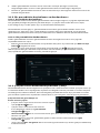 538
538
-
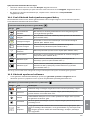 539
539
-
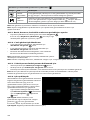 540
540
-
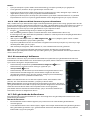 541
541
-
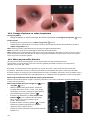 542
542
-
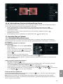 543
543
-
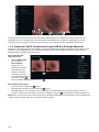 544
544
-
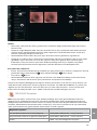 545
545
-
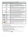 546
546
-
 547
547
-
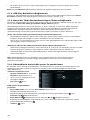 548
548
-
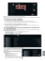 549
549
-
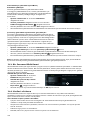 550
550
-
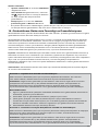 551
551
-
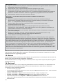 552
552
-
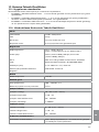 553
553
-
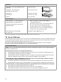 554
554
-
 555
555
-
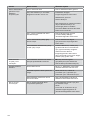 556
556
-
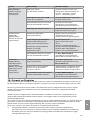 557
557
-
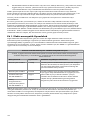 558
558
-
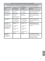 559
559
-
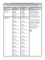 560
560
-
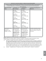 561
561
-
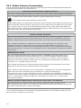 562
562
-
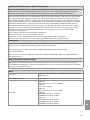 563
563
-
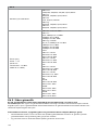 564
564
-
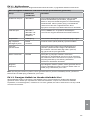 565
565
-
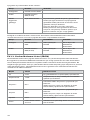 566
566
-
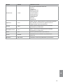 567
567
-
 568
568


diğer dillerde
- slovenčina: Ambu aBox™ 2 Návod na používanie
- română: Ambu aBox™ 2 Instrucțiuni de utilizare
İlgili makaleler
Diğer belgeler
-
Samsung PS50C535C1W Kullanım kılavuzu
-
-
Samsung PS42C450 Kullanım kılavuzu
-
VESTEL 42PF8575 Operating Instructions Manual
-
VESTEL 55PF8055 Operating Instructions Manual
-
Yamaha RX-V3900 Kullanım kılavuzu
-
-
-
Levenhuk DTX 350 Kullanım kılavuzu
-