Yamaha PWK-242 El kitabı
- Kategori
- Düz panel duvar askı aparatları
- Tip
- El kitabı

ENGLISH FRANÇAIS DEUTSCH SVENSKA ESPAÑOL
PWK-242
Wall mounting unit
Dispositif d’installation murale
Installation Instructions
Mode d’emploi
Aufstellungsanweisungen
Installationsanvisningar
Instrucciones para la Instalación

1
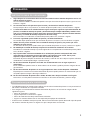
Thank you for purchasing the Wall Mounting Unit.
To ensure correct usage, please read this instruction manual thoroughly. After reading, please store this
manual in a safe place for future reference.
This Wall Mounting Unit is for use only with the following models:
• PDM-4210
• PDM-4210E
• Before installing the wall mounting unit, please read these instructions and the plasma monitor user’s
manual carefully to ensure installation is carried out correctly.
• After installation, please give the instructions to the customer for future reference.
■
All installation work must be performed by a qualified contractor or by dealer personnel.
■
The customer should never attempt to perform this installation work.
■
YAMAHA assumes absolutely no responsibility for injuries and damages that may occur due to
improper installation and handling.
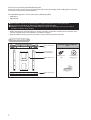
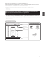
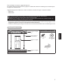
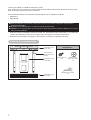
Included in the component
bag
Component list
Wall mounting unit
(A)
Wall mounting unit
(B)
Wall mounting unit
(C)
Plasma monitor
mounting bracket
M6x18 screws
x 10
Flat washer for
M5–6 screws
x 8
Cable clamp
x 2

2
ENGLISH
1. Always follow the instructions set forth in this manual when installing the plasma monitor
using this wall mounting unit.
Improper or inadequate installation could cause the plasma monitor to fall and injure someone.
2. Two or more persons are required to install and remove the plasma monitor.
If two or more persons are not present, the plasma monitor may fall and injure someone.
3. The installation must be secure enough to bear the weight of the plasma monitor, the wall
mounting unit, and other hardware indefinitely, and must also be secure enough to withstand
vibration. (Total weight of the plasma monitor and wall mounting unit is approximately 37kg
(81 lbs. 9 oz.))
The plasma monitor may fall and injure someone if the installation is inadequate.
4. To ensure safety, tighten all bolts and screws securely.
Loose screws could cause the plasma monitor to fall and injure someone.
5. Use only the parts provided with the wall mounting unit, and any other parts that are specified
in this manual.
Using other parts could cause the plasma monitor to fall and injure someone.
6. Do not modify the wall mounting unit or the parts provided with the mounting unit.
Modifying the wall mounting unit or the other parts could cause the plasma monitor to fall and injure
someone.
7. Be sure to leave enough open space around the unit to allow heat generated by the plasma
monitor. Maintain at least 10 cm (3-15/16 inches) at the top, bottom and sides of the plasma
monitor.
The plasma monitor has air intake holes and outlet holes. Failure to provide adequate space around
the unit may cause a fire.
8. Do not install the plasma monitor in a location near an air conditioning vent or in a location
subject to vibration.
Such conditions could have an adverse effect on the monitor, and could cause a fire or electric shock.
9. Do not install the plasma monitor in a location that is subject to high levels of dust or humidity.
Dust accumulating inside the plasma monitor could cause a short circuit that in turn could cause a fire
or electric shock.
10. Do not install the plasma monitor face up, sideways or upside down, or inclined on an angle.
Doing so may cause heat to build up inside the monitor, and may cause a fire.
• The wall mounting unit is for use in installing the plasma monitor on a vertical wall. Do not install the unit
on an inclined surface.
•To ensure correct operation of the plasma monitor, do not install it in any of the following places.
–Next to sprinklers or sensors
– Locations subject to vibration or shocks
– Close to high–voltage wires or electric motors
– Locations in direct contact with air expelled from heating devices
• When installing this wall mounting unit, use a fixing method appropriate to the type of wall.
• Do not install plasma monitor in locations with a temperature above.
Caution
SAFETY INSTRUCTIONS
Precautions for installation

3
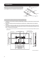
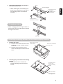
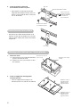
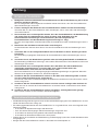
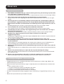
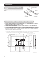
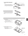
Using 4 M6x18 screws, assemble the wall mounting unit.
1. Prepare 4 sets of screws or anchors (commercially available) to suit the wall you wish to mount
the unit on.
2. Read this installation manual thoroughly, then decide on a suitable location for the plasma
monitor.
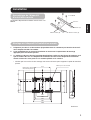
3. The position of the outer edge and screen of the plasma monitor and screw holes on the wall
mounting unit are depicted in the diagram below. Anchor the wall mounting unit and drill screw
holes as indicated in the diagram.
• Check that the wall and screws you want to mount this unit on are strong enough to hold the plasma
monitor unit.
Installation
4 M6x18 screws
Wall mounting unit
(C)
Wall mounting unit
(B)
Wall mounting unit
(A)
Notch
Assembling the wall mounting unit
Attaching the wall mounting unit to a wall
414 (16-5/16)
266 (10-1/2)
300 (11-13/16)
300 (11-13/16)
51(2)
249 (9-13/16)
318 (12-1/2)
636 (25-1/16)
69 (2-11/16)
126 (4-15/16)
35
(1-3/8)
400 (15-3/4)
1030 (40-9/16)
450 (17-11/16)
500 (19-11/16)
Plasma monitor
external dimensions
Screw holes 7x20
Screen
center
Unit: mm (inches)

4
ENGLISH
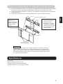
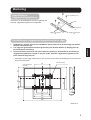
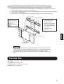
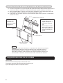
4. Attach the wall mounting unit firmly to
the surface of the wall.
• When attaching the wall mounting unit,
drill at least 2 deep holes in the wall for
the mounting screws to a balanced
mounting.
• When arranging power and signal cables on
the rear of the unit, use cable clips to prevent
damage to the cables.
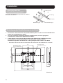
1. Remove the stand
(1) Remove the 4 screws from the rear of
the plasma monitor and then remove
the stand.
(2) Remove the 4 continuous thread
screws attaching the earth on the rear
cover.
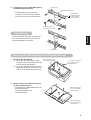
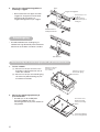
2. Attaching the plasma monitor mounting
bracket.
• Use 4 M6x18 screws to attach the
monitor mounting rack to the plasma
monitor.
Notch
Wall mounting unit
Ensure that you are
attaching the
mounting unit to a
strong support.
Use the washers
included as necessary.
Cable clip
Arranging cables
Attaching mounting fixtures to the plasma display monitor
Remove the 4 continous
thread screws
Remove the 4 screws
and the stand
Second hole from
the top of the
monitor mounting
bracket
Fifth hole from the
top of the monitor
mounting bracket

5
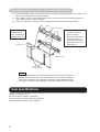
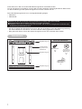
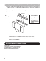
(1) Insert the hooked section on the top of the plasma monitor mounting bracket into the notch in the
top of the wall mounting unit and pull it down.
(2) Use 2 M6x18 screws inserted through the holes in the underside of the mounting bracket to
attach it firmly to the wall mounting unit.
(3) Check that the plasma monitor is firmly attached to the wall, then connect the cables.
Note
Connect speaker cables to the speaker terminals on the rear of the plasma
monitor prior to mounting it in the wall mounting unit. Connect the speaker
cables to the speakers after mounting the monitor in the mounting unit. For
instructions on attaching the speakers, refer to the speaker owner’s manual.
Weight : 2.5 kg (5 lbs. 8 oz.)
Main construction material : Steel plate
Surface treatment : Black electrostatic painting
Angle adjustment: Vertical screen position
Mounting the plasma monitor to the wall mounting unit
Check that the
hooked section is
firmly seated in the
wall mounting unit.
• Always use at least 2
people to carry the
plasma monitor.
• Remove all the cables
and cords from the
plasma monitor before
mounting it in the wall
mounting unit.
Notch
Wall mounting unit
Hooked section
2 M6x18 screws
Plasma monitor
mounting bracket
Item specifications

1
FRANÇAIS
Merci d’avoir porté votre choix sur cet dispositif d’installation murale.
Veuillez lire entièrement ce mode d’emploi afin d’utiliser correctement le produit. Conservez ensuite ce
mode d’emploi en lieu sûr afin de pouvoir le consulter ultérieurement.
Cet dispositif d’installation murale est conçu exclusivement pour les modèles suivants:
• PDM-4210
• PDM-4210E
•Pour monter correctement cet dispositif d’installation murale, veuillez lire entièrement et attentivement
ces instructions ainsi que le mode d’emploi du moniteur plasma haute définition avant de commencer
l’installation.
• Après l’installation, remettez cette documentation au client en lui demandant de la conserver pour toute
référence ultérieure.
■
Tout travail d’installation doit être exécuté par un technicien qualifié ou par un revendeur agréé.
■
Le client ne doit jamais tenter d’effectuer lui-même cette installation.
■
YAMAHA rejette toute responsabilité pour tout dommage ou blessure résultant d’une installation ou
manipulation inappropriée.
Contenu du sachet fourni
Liste des éléments
Attache murale (A)
Attache murale (B)
Attache murale (C)
Support de mon-
tage pour moniteur
plasma
Vis M6x18
x 10
Rondelle plate
pour vis M5-6
x8
Porte-câble
x2

2
1. Suivez scrupuleusement les consignes énoncées dans ce manuel pour monter le moniteur
plasma avec cet dispositif d’installation murale.
Toute erreur de montage pourrait entraîner la chute du moniteur plasma et occasionner des blessures.
2. L’installation et le démontage du moniteur plasma requièrent au moins deux personnes.
Sans la présence d’au moins deux personnes, le moniteur plasma risque de tomber et d’occasionner
des blessures.
3. Le montage doit supporter le poids du moniteur plasma, de l’dispositif d’installation murale et
de tout autre matériel à long terme. Le montage doit en outre résister aux vibrations. (Le poids
total du moniteur plasma et de l’dispositif d’installation murale est d’environ 37kg.)
Si le montage est incorrect, le moniteur plasma risque de tomber et d’occasionner des blessures.
4. Serrez fermement tous les boulons et vis pour obtenir un montage sûr.
Des vis ou boulons mal serrés pourraient provoquer la chute du moniteur plasma et occasionner des
blessures.
5. Utilisez exclusivement les pièces fournies avec l’dispositif d’installation murale et toute autre
pièce spécifiée dans ce manuel.
L’utilisation d’autres pièces pourrait provoquer la chute du moniteur plasma et occasionner des bles-
sures.
6. Ne modifiez pas l’dispositif d’installation murale ni aucune des pièces l’accompagnant.
Toute modification de l’dispositif d’installation murale ou des autres pièces pourrait provoquer la chute
du moniteur plasma et occasionner des blessures.
7. Veillez à conserver un espace suffisant autour du moniteur plasma pour permettre la
dissipation de la chaleur produite par l’appareil. Gardez un espace libre d’au moins 10cm sur
le dessus, le dessous et les côtés du moniteur plasma.
Le moniteur plasma est doté d’orifices d’entrée et de sortie d’aération. Toute insuffisance d’espace
libre autour du moniteur pourrait causer un incendie.
8. N’installez pas le moniteur plasma à proximité de l’évent d’une climatisation ni dans un endroit
soumis à des vibrations.
Ces facteurs pourraient nuire au moniteur et causer un incendie ou une électrocution.
9. N’installez pas le moniteur plasma dans un endroit excessivement humide ou poussiéreux.
L’accumulation de poussière à l’intérieur du moniteur plasma pourrait provoquer un court-circuit cons-
tituant un risque d’incendie ou d’électrocution.
10. N’installez pas le moniteur plasma en orientant son écran vers le haut ou en biais. Ne l’inclinez
pas et ne l’installez pas à l’envers.
Cela pourrait provoquer une accumulation de chaleur à l’intérieur du moniteur et causer un incendie.
•L’dispositif d’installation murale est conçu pour fixer le moniteur plasma à un mur vertical. Ne l’installez
pas sur une surface inclinée.
•Pour garantir un fonctionnement correct du moniteur plasma, ne l’installez jamais dans des endroits:
–à proximité de capteurs ou de crépine d’incendie
– soumis à des vibrations ou des chocs
–à proximité de câbles haute tension ou de moteurs électriques
–à proximité directe du flux d’air chaud produit par des appareils de chauffage
• Montez cet dispositif d’installation murale en utilisant une méthode adaptée au type de mur en question.
• N’installez jamais le moniteur plasma à proximité d’une source de chaleur.
Attention
CONSIGNES DE SÉCURITÉ
Précautions pour l’installation

3
FRANÇAIS
Assemblez l’dispositif d’installation murale avec 4 vis
M6x18.
1. Préparez 4 jeux de vis ou de crochets (disponibles dans le commerce) en fonction du mur où
vous comptez installer l’ensemble.
2. Lisez complètement ce manuel d’installation et choisissez l’emplacement de montage
approprié pour le moniteur plasma.
3. Le schéma ci-dessous illustre la position du périmètre extérieur et de l’écran du moniteur ainsi
que les orifices des vis sur l’dispositif d’installation murale. Posez l’dispositif d’installation
murale et forez des trous pour les vis comme spécifié sur le schéma.
• Vérifiez que le mur et les vis de montage sont assez résistants pour supporter le poids du moniteur
plasma.
Installation
4 vis M6x18
Attache murale (C)Attache murale (B)
Attache murale (A)
Encoche
Assemblage de l’dispositif
d’installation murale
Montage de l’dispositif d’installation murale
414
266
300
300
51249
318
636
69
126
35
400
1030
450
500
Dimensions externes
du moniteur plasma
Orifices pour vis de 7x20
Centre de
l’écran
Unité: mm

4
4. Fixez fermement l’dispositif
d’installation murale à la paroi.
•Pour obtenir un montage correct de
l’dispositif d’installation murale, forez au
moins 2 trous profonds dans le mur pour
les vis de fixation.
• Acheminez les câbles d’alimentation et de
signaux au dos de l’ensemble en les serrant
avec les porte-câbles pour éviter tout endom-
magement.
1. Retirez le socle.
(1) Desserrez les 4 vis au dos du moniteur
plasma et retirez le socle.
(2) Retirez les 4 vis à pas continu au dos
du moniteur.
2. Fixez le support de montage pour
moniteur plasma.
• Fixez le support de montage sur le
moniteur plasma à l’aide de 4 vis M6x18.
Encoche
Dispositif d’installation murale
Assurez-vous que
la surface recevant
l’dispositif d’installa-
tion murale est
assez résistante.
Si nécessaire, utilisez
les rondelles fournies.
Porte-câble
Acheminement des câbles
Montage des fixations sur l’écran plasma
Retirez les 4 vis à pas
continu.
Desserrez les 4 vis et
ôtez le socle.
Deuxième orifice à
partir du haut du
support de mon-
tage du moniteur
Cinquième orifice à
partir du haut du
support de mon-
tage du moniteur

5
FRANÇAIS
(1) Glissez les extrémités crochues (sur le dessus du support de montage du moniteur plasma) dans
les encoches (en haut de l’dispositif d’installation murale) et tirez le support vers le bas.
(2) Vissez fermement 2 vis M6x18 sur le dessous du support de montage pour le fixer à l’dispositif
d’installation murale.
(3) Vérifiez que le moniteur plasma est correctement fixé au mur et branchez les câbles.
Remarque
Branchez les câbles d’enceintes aux prises prévues à cet effet sur le dos du
moniteur plasma avant de le fixer à l’dispositif d’installation murale Branchez
l’autre extrémité de ces câbles aux enceintes une fois que le moniteur est fixé à
l’dispositif d’installation murale. Pour en savoir plus sur le montage des encein-
tes, voyez leur mode d’emploi.
Poids: 2,5kg
Matériau principal: plaque en acier
Traitement: peinture noire électrostatique
Angle de montage: écran en position verticale
Montage du moniteur plasma sur l’dispositif d’installation murale
Vérifiez que les
extrémités cro-
chues sont bien en
place sur l’disposi-
tif d’installation
murale.
• Il faut au moins 2 per-
sonnes pour porter le
moniteur plasma.
• Retirez tous les câbles
et cordons du moniteur
plasma avant de le mon-
ter sur l’dispositif d’ins-
tallation murale.
Encoche
Dispositif d’installation murale
Extrémité crochue
2 vis M6x18
Support de montage
pour moniteur plasma
Spécifications

1
Vielen Dank, dass Sie sich für diese Wandhalterungseinheit entschieden haben.
Um sie sachgerecht zu installieren, müssen Sie sich diese Anleitung vollständig durchlesen. Bitte bewah-
ren Sie die Anleitung für die spätere Bezugnahme an einem sicheren Ort auf.
Diese Wandhalterungseinheit ist nur für folgende Modelle geeignet:
• PDM-4210
• PDM-4210E
•Vor der Installation der Wandhalterung müssen Sie sich die Anleitung sowie die Bedienungsanleitung
des Plasmabildschirms durchlesen, um die Installation ordnungsgemäß auszuführen.
• Bitte geben Sie dieses Heft für die spätere Bezugnahme nach der Installation dem Kunden.
■
Überlassen Sie die Installation einem qualifizierten Installateur oder Ihrem Händler.
■
Anwender dürfen die Installation auf keinen Fall selbst vornehmen.
■
YAMAHA haftet nicht für Verletzungen oder Schäden, die auf eine unsachgemäße Installation oder
Handhabung zurückzuführen sind.
Inhalt der Zubehörtüte
Zubehörteile
Wandhalterung (A)
Wandhalterung (B)
Wandhalterung (C)
Installationshalte-
rung für den Plas-
mabildschirm
M6x18-Schrau-
ben
x10
Flache Unter-
legscheibe für
M5-6-Schrau-
ben
x8
Kabelbinder
x2

2
DEUTSCH
1. Befolgen Sie für die Installation des Plasmabildschirms mit dieser Wandhalterung alle in dieser
Anleitung erwähnten Schritte.
Eine unsachgemäße oder mangelhafte Installation könnte dazu führen, dass der Plasmabildschirm
fällt und Verletzungen verursacht.
2. Für das Anbringen oder Entfernen des Plasmabildschirms werden zwei Personen benötigt.
Versuchen Sie nie, den Plasmabildschirm allein anzubringen, weil er sonst fallen und Verletzungen
verursachen könnte.
3. Die Installation muss so durchgeführt werden, dass der Plasmabildschirm, die Wandhalterung
und andere Teile für unbegrenzte Zeit sicher verankert sind. Außerdem muss die
Gesamteinheit Erschütterungen aushalten können. (Das Gesamtgewicht des
Plasmabildschirms und der Wandhalterungseinheit beträgt ca. 37kg.)
Bei einer unsachgemäßen Installation könnte der Plasmabildschirm fallen und Verletzungen verursa-
chen.
4. Bitte drehen Sie alle Muttern und Schrauben vollständig fest.
Lockere Schrauben könnten dazu führen, dass der Plasmabildschirm fällt und Verletzungen verur-
sacht.
5. Verwenden Sie nur das beiliegende Zubehör bzw. ausdrücklich in dieser Anleitung erwähnte
Zusatzteile.
Bei Verwendung ungeeigneter Teile könnte der Plasmabildschirm fallen und Verletzungen verursa-
chen.
6. Versuchen Sie nie, die Wandhalterungseinheit oder das beiliegende Zubehör zu modifizieren.
Bei Verwendung modifizierter Halterungs- oder anderer Teile könnte der Plasmabildschirm fallen und
Verletzungen verursachen.
7. Die Installation muss so durchgeführt werden, dass die Wärme des Plasmabildschirms
ungehindert entweichen kann. Lassen Sie über, unter und an beiden Seiten des
Plasmabildschirms einen Freiraum von mindestens 10cm.
Der Plasmabildschirm ist mit Lüftungseingängen und Entlüftungsöffnungen ausgestattet. Wenn die
Warmluft nicht abgeführt werden kann, besteht Brandgefahr.
8. Installieren Sie den Plasmabildschirm niemals in der Nähe einer Klimaanlage oder an einem
Ort, der starken Erschütterungen ausgesetzt ist.
Das könnte nämlich die Funktionstüchtigkeit des Bildschirms beeinflussen und zu Brand bzw. einem
Stromschlag führen.
9. Installieren Sie den Plasmabildschirm niemals an einem extrem staubigen oder feuchten Ort.
Staub, der sich im Inneren des Plasmabildschirms ansammelt, könnte zu Brand bzw. einem Strom-
schlag führen.
10. Installieren Sie den Plasmabildschirm niemals umgekehrt, seitlich gedreht oder geneigt.
Sonst wird er nämlich zu heiß, und dann besteht Brandgefahr.
• Die Wandhalterungseinheit eignet sich nur für die vertikale Befestigung des Plasmabildschirms an einer
Wand. Die Wand darf nicht schräg sein.
• Ein ordnungsgemäßer Betrieb des Plasmabildschirms ist nur gewährleistet, wenn man folgende Instal-
lationsorte meidet.
– In der Nähe von Sprühvorrichtungen oder Sensoren
–Orte, die starken Schwingungen oder Erschütterungen ausgesetzt sind
– In der Nähe von Hochspannungskabeln oder elektrischen Motoren
– In der Nähe von Warmluftschächten eines Heizsystems
• Wählen Sie für die Installation der Wandhalterung ein Befestigungssystem das für die Wandbeschaffen-
heit geeignet ist.
•Bringen Sie den Plasmabildschirm niemals in der Nähe einer Wärmequelle an.
Achtung
SICHERHEITSHINWEISE
Vorsichtsmaßnahmen für die Installation

3
Bauen Sie die Wandhalterungseinheit mit 4 M6x18-
Schrauben zusammen.
1. Bereiten Sie 4 Schraubensätze oder (handelsübliche) Haken vor, die sich für die Wandbeschaf-
fenheit des Installationsortes eignen.
2. Lesen Sie sich diese Installationsanleitung sorgfältig durch, um einen geeigneten
Installationsort für den Plasmabildschirm zu wählen.
3. In dem Schema unten sehen Sie die Anordnung des Außenrandes und Bildschirms des
Plasmamonitors sowie der Bohrungen für die Schrauben. Verankern Sie die
Wandhalterungseinheit und bohren Sie an den gezeigten Stellen Löcher in die Wand.
•Kontrollieren Sie, ob die Wand und Schrauben das Gewicht des Plasmabildschirms aushalten.
Installation
4 M6x18-Schrau-
ben
Wandhalterung (C)Wandhalterung (B)
Wandhalterung (A)
Aussparung
Zusammenbau der
Wandhalterungseinheit
Befestigung der Wandhalterung an der Wand
414
266
300
300
51249
318
636
69
126
35
400
1030
450
500
Außenabmessungen
des Plasmabildschirms
Bohrungen 7x20
Bildschirm-
mitte
Einheit: mm

4
DEUTSCH
4. Sorgen Sie für eine stabile Befestigung
der Wandhalterungseinheit.
• Für die Wandmontage sollten Sie
mindestens zwei tiefe Löcher bohren,
um einen festen Sitz zu gewährleisten.
• Für die Installation des Netz- und Signalka-
bels an der Rückseite der Einheit müssen
Sie die Kabelbinder verwenden.
1. Entfernen Sie den Ständer
(1) Lösen Sie die 4 Schrauben an der
Rückseite des Plasmabildschirms und
entnehmen Sie den Ständer.
(2) Lösen Sie die 4 Schrauben mit durch-
gehendem Gewinde, mit welchen der
Sockel an der Rückplatte befestigt ist.
2. Bringen Sie die Installationshalterung
am Plasmabildschirm an
•Verwenden Sie 4 M6x18-Schrauben für
die Befestigung der
Installationshalterung am
Plasmabildschirm.
Aussparung
Wandhalterungseinheit
Die Wandhalte-
rungseinheit muss
fest in der Wand
verankert werden.
Verwenden Sie bei
Bedarf auch die beilie-
Kabelbinder
Kabelführung
Anbringen des Montagebügels am Plasmabildschirm
Lösen Sie die 4 Schrau-
ben mit durchgehen-
dem Gewinde
Die 4 Schrauben und
den Ständer entfernen
Zweite Bohrung von
oben in der Installa-
tionshalterung
Fünfte Bohrung von
oben in der Installa-
tionshalterung

5
(1) Schieben Sie die Halterungsbügel an der Oberseite der Plasmabildschirm-Installationshalterung
in die Aussparungen an der Oberseite der Wandhalterungseinheit und ziehen Sie den Bildschirm
nach unten.
(2) Verwenden Sie 2 M6x18-Schrauben, die Sie von unten in die Wandhalterungseinheit drehen, für
die Arretierung des Bildschirms an der Wandhalterungseinheit.
(3) Kontrollieren Sie, ob der Plasmabildschirm auch wirklich fest sitzt. Schließen Sie danach die
Kabel an.
Achtung
Vor der Verankerung in der Wandhalterungseinheit müssen Sie die Lautspre-
cherkabel auf der Rückseite des Plasmabildschirms anschließen. Verbinden Sie
die Lautsprecherkabel erst nach der Verankerung des Bildschirms in der Halte-
rungseinheit mit den Boxen. Hinweise zur Installation der Boxen finden Sie in der
Bedienungsanleitung der Boxen.
Gewicht: 2,5kg
Hauptsächlich verwendetes Material: Stahlplatte
Verarbeitung: Schwarze elektrostatische Farbe
Einbauwinkel: Vertikale Bildschirmposition
Befestigung des Plasmabildschirms an der Wandhalterungseinheit
Die
Halterungsbügel
müssen fest in der
Wandhalterungsei
nheit sitzen.
• Der Plasmabildschirm
muss von mindestens 2
Personen gehalten und
abgestützt werden.
• Lösen Sie alle Kabel
des Plasmabildschirms,
bevor Sie ihn auf die
Wandhalterungseinheit
schieben.
Aussparung
Wandhalterungseinheit
Halterungsbügel
2 M6x18-Schrauben
Installationshalterung für
den Plasmabildschirm
Technische Daten des Produkts

1
SVENSKA
Tack för inköpet av Yamahas väggmonteringssats.
Läs igenom denna monteringsanvisning noga för att tillförsäkra korrekt användning. Spara monteringsan-
visningen för framtida behov.
Väggmonteringssatsen PWK-242 är endast avsedd att användas till någon av följande modeller:
• PDM-4210
• PDM-4210E
• Se till att läsa igenom denna monteringsanvisning och plasmaskärmens bruksanvisning noggrant, innan
väggmonteringssatsen används, för att tillförsäkra korrekt montering.
•Överlämna monteringsanvisningen till kunden för eventuellt framtida behov efter att monteringen är klar.
■ Allt monteringsarbete måste utföras av en kvalificerad leverantör eller återförsäljare.
■ Kunden bör aldrig själv försöka utföra detta monteringsarbete.
■ YAMAHA påtar sig inget som helst ansvar för eventuella personskador eller materiella skador som
uppstått till följd av felaktig montering eller hantering.
Inkluderat i tillbehörspåsen
Medföljande delar
Väggmonteringsplåt
(A)
Väggmonteringsplåt
(B)
Väggmonteringsplåt
(C)
Monteringsplåt för
plasmaskärmen
Skruv (M6x18)
x 10
Platt bricka till
skruv (M5–M6)
x 8
Kabelklämma
x 2

2
1. Följ alltid de instruktioner som ges i denna monteringsanvisning vid montering av plasmaskär-
men med hjälp av väggmonteringssatsen.
Felaktig eller bristfällig montering kan resultera i att plasmaskärmen ramlar ner och att någon skadas.
2. Minst två personer krävs för montering och demontering av plasmaskärmen.
Om inte två personer finns tillgängliga kan det hända att plasmaskärmen ramlar ner och att någon
skadas.
3. Monteringen måste vara tillräckligt stadig för att kunna bära den sammanlagda tyngden hos
plasmaskärmen, väggmonteringssatsen och övriga tillbehör på obestämd tid och dessutom
kunna motstå vibrationer. (Plasmaskärmen och monteringssatsen väger tillsammans cirka 37
kg.)
Bristfällig montering kan resultera i att plasmaskärmen ramlar ner och att någon skadas.
4. Dra åt alla bultar och skruvar ordentligt för att tillförsäkra säkerheten.
Löst sittande skruvar kan resultera i att plasmaskärmen ramlar ner och att någon skadas.
5. Använd endast de delar som följer med väggmonteringssatsen och andra delar som anges i
denna monteringsanvisning.
Användning av andra delar kan resultera i att plasmaskärmen ramlar ner och att någon skadas.
6. Modifiera inte väggmonteringssatsen eller någon av de delar som följer med
väggmonteringssatsen.
Modifiering av väggmonteringssatsen eller någon medföljande del kan resultera i att plasmaskärmen
ramlar ner och att någon skadas.
7. Se till att lämna tillräckligt stort utrymme runt plasmaskärmen för den värme som
plasmaskärmen avger. Lämna minst 10 centimeters mellanrum ovanför, under och vid sidorna
av plasmaskärmen.
Plasmaskärmen har ventilationsöppningar för intagning och utsläppning av luft. Underlåtenhet att
sörja för tillräckligt stort ventilationsutrymme runt plasmaskärmen kan förorsaka brand.
8. Montera inte plasmaskärmen intill en luftkonditioneringsventil eller på en plats som utsätts för
vibrationer.
Sådana förhållanden kan ha skadlig effekt på plasmaskärmen och kan förorsaka brand eller elektriska
stötar.
9. Montera inte plasmaskärmen på en plats där det är mycket dammigt eller fuktigt.
Damm som samlas inuti plasmaskärmen kan förorsaka kortslutning som i sin tur kan orsaka brand
eller elektriska stötar.
10. Montera inte plasmaskärmen vänd uppåt, åt sidan eller uppochner eller i lutande läge.
Sådan montering kan leda till överhettning inuti plasmaskärmen, vilket kan orsaka brand.
• Väggmonteringssatsen är avsedd för montering av plasmaskärmen på en lodrät vägg. Montera inte
plasmaskärmen på en lutande yta.
• Undvik att montera plasmaskärmen på någon av följande platser för att tillförsäkra dess korrekta funk-
tion:
– intill en sprinkler eller en sensor,
– på en plats där den kan utsättas för vibrationer eller stötar,
–i närheten av en högspänningsledning eller en elmotor,
– på en plats där den utsätts för varm luft från en värmekälla.
•Använd en lämplig fästmetod enligt väggtypen ifråga vid montering av väggmonteringssatsen på väg-
gen.
• Montera inte plasmaskärmen på en alltför varm plats.
Observera
Säkerhetsföreskrifter
Försiktighetsåtgärder vid montering

3
SVENSKA
Använd fyra av de medföljande skruvarna (M6x18) och
sätt ihop väggmonteringsplåtarna enligt bilden.
1. Förbered fyra stycken skruvar eller ankarbultar (tillval) som passar för den vägg som plasma-
skärmen ska monteras på.
2. Läs noggrant igenom denna monteringsanvisning och bestäm därefter en lämplig plats för
plasmaskärmens montering.
3. Plasmaskärmens ytterkanter och själva skärmens placering i förhållande till skruvhålen på
väggmonteringsplåtarna framgår av skissen nedan. Förankra väggmonteringsplåtarna och
borra skruvhål enligt skissen.
•Kontrollera att den vägg och de skruvar som är tänkta att användas är tillräckligt starka för att kunna
bära plasmaskärmen.
Montering
Skruv (M6x18) (4 st.)
Väggmonteringsplåt
(C)
Väggmonteringsplåt
(B)
Väggmonteringsplåt
(A)
Skåra
Hopsättning av
väggmonteringsplåtarna
Fastsättning av väggmonteringsplåtarna på en vägg
414
266
300
300
51249
318
636
69
126
35
400
1030
450
500
Plasmaskärmens
yttermått
Skruvhål (7x20)
Skärmens
mitt
Enhet: mm

4
4. Skruva fast väggmonteringsplåtarna
ordentligt i väggen.
• Borra åtminstone två djupa skruvhål i
väggen för att uppnå en balanserad
montering vid fastsättning av
väggmonteringsplåtarna på väggen.
•Använd kabelklämmor vid dragning av
nätkabel och signalkabel till plasmaskärmens
baksida för att undvika att kablarna skadas.
1. Ta loss sockeln.
(1) Skruva loss de fyra skruvarna från
baksidan på plasmaskärmen och ta
sedan loss sockeln.
(2) Skruva loss de fyra återstående gäng-
skruvarna för jordanslutning på plas-
maskärmens baksida.
2. Skruva fast monteringsplåtarna på
plasmaskärmen.
•Använd fyra av de medföljande
skruvarna (M6x18) och fäst
monteringsplåtarna på plasmaskärmen
enligt bilden.
Skåra
Väggmonteringsplåtar
Ensure that you are
Se till att
väggmonterings-
plåtarna fästs på en
stadig yta.
Använd vid behov
medföljande brickor.
Kabelklämma
Kabeldragning
Fastsättning av monteringsplåtar på plasmaskärmen
Skruva loss de fyra
återstående gäng-
skruvarna.
Skruva loss de fyra
skruvarna och ta
loss sockeln.
Second hole from
Andra hålet uppi-
från på monterings-
plåten
Femte hålet uppifrån
på monteringsplåten
Sayfa yükleniyor...
Sayfa yükleniyor...
Sayfa yükleniyor...
Sayfa yükleniyor...
Sayfa yükleniyor...
Sayfa yükleniyor...
Sayfa yükleniyor...
-
 1
1
-
 2
2
-
 3
3
-
 4
4
-
 5
5
-
 6
6
-
 7
7
-
 8
8
-
 9
9
-
 10
10
-
 11
11
-
 12
12
-
 13
13
-
 14
14
-
 15
15
-
 16
16
-
 17
17
-
 18
18
-
 19
19
-
 20
20
-
 21
21
-
 22
22
-
 23
23
-
 24
24
-
 25
25
-
 26
26
-
 27
27


Yamaha PWK-242 El kitabı
- Kategori
- Düz panel duvar askı aparatları
- Tip
- El kitabı
diğer dillerde
- español: Yamaha PWK-242 El manual del propietario
- français: Yamaha PWK-242 Le manuel du propriétaire
- italiano: Yamaha PWK-242 Manuale del proprietario
- svenska: Yamaha PWK-242 Bruksanvisning
- Deutsch: Yamaha PWK-242 Bedienungsanleitung
- English: Yamaha PWK-242 Owner's manual
- dansk: Yamaha PWK-242 Brugervejledning
- suomi: Yamaha PWK-242 Omistajan opas
- Nederlands: Yamaha PWK-242 de handleiding
- română: Yamaha PWK-242 Manualul proprietarului