Whirlpool AKR 769 AV Program Chart
- Kategori
- Oyuncaklar
- Tip
- Program Chart
Bu kılavuz aynı zamanda aşağıdakiler için de uygundur:

5019 318 33077
AKR 604-605-606-769
AKR 770-771-772
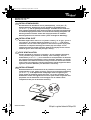
INSTALLATIONSANGABEN
Mindestabstand zur Kochfläche: 65 cm (Elektroplatten), 75 cm (Gas-, Öl-,
Kohlekochplatten). Befolgen Sie bei der Installation die Nummerierung
(1
Ö
2
Ö
3
Ö
.....) und die jeweiligen Anleitungen. Schließen Sie das Gerät erst
nach erfolgter Installation an die Stromversorgung an. Achtung! Das Auslassrohr
und die Befestigungsmanschetten sind nicht im Lieferumfang inbegriffen und
müssen gesondert erworben werden. Der Polystyrolstreifen im Fettfilter-
Halterungsrahmen muss entfernt werden (siehe nachfolgende Abbildung).
INSTALLATION SHEET
Minimum height above cooker: 65 cm (electric cookers), 75 cm (gas, gas oil or
coal cookers). To assemble follow the numbers (1
Ö
2
Ö
3
Ö
.....) and relative
instructions. Do not connect the appliance to the electrical power supply until
installation is completed. Warning! The exhaust pipe and clamps are not
supplied and must be bought separately. Remove the polystyrene bar located
inside the grease filters surround (see figure below).
FICHE D'INSTALLATION
Distance minimale par rapport à la cuisinière : 65 cm (cuisinière électrique),
75 cm (cuisinière à gaz, mazout ou charbon). Pour le montage, suivez la
numérotation (1
Ö
2
Ö
3
Ö
.....) et les instructions correspondantes. Ne branchez
pas l'appareil tant que l'installation n'est pas terminée. Attention ! Le conduit
d'évacuation et les colliers de fixation ne sont pas fournis et doivent être achetés
à part. La barre en polystyrène, située à l'intérieur du cadre du support des filtres
à graisses, doit être démontée (voir illustration ci-dessous).
INSTALLATIEKAART
Minimumafstand tot het kooktoestel: 65 cm (elektrische kooktoestellen), 75 cm
(kooktoestellen op gas, gasolie of kolen). Volg voor de montage de nummering
(1
Ö
2
Ö
3
Ö
.....) en de bijbehorende aanwijzingen. Geef het apparaat geen
stroom totdat de installatie geheel voltooid is. Let op! De afvoerbuis en de
klembanden worden niet bijgeleverd en moeten apart worden aangeschaft. Het
piepschuim aan de binnenkant van de draaglijst van de vetfilters moet
verwijderd worden (zie de illustratie hieronder).
D
GB
F
NL
31833077.fm Page 1 Wednesday, April 9, 2003 11:13 AM

5019 318 33077
AKR 604-605-606-769
AKR 770-771-772
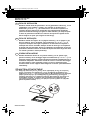
FICHA DE INSTALACIÓN
Distancia mínima desde los quemadores: 65 cm (quemadores eléctricos), 75 cm
(quemadores a gas, gasóleo o carbón). Para efectuar el montaje siga la
numeración (1
Ö
2
Ö
3
Ö
.....) y las instrucciones. No conecte el aparato a la
corriente eléctrica hasta que la instalación esté completamente finalizada.
¡Atención! El tubo de descarga y las guías no están incluidas y se compran aparte.
La barra de poliestireno situada en el interior del soporte de sujeción de los
filtros antigrasa se quita (via la figura de más abajo).
FICHA DE INSTALAÇÃO
Distância mínima dos fogões: 65 cm (fogões eléctricos), 75 cm (fogões a gás,
óleo ou carbono). Para a montagem, siga a numeração (1
Ö
2
Ö
3
Ö
.....) e as
respectivas instruções. Não ligue o aparelho à corrente eléctrica enquanto a
instalação não estiver concluída. Atenção! O tubo de descarga e as braçadeiras
de fixação não são fornecidos. Devem ser adquiridos separadamente. A barra de
poliestireno situada no interior do caixilho de suporte dos filtros de gordura deve
ser retirada (consulte a ilustração abaixo).
SCHEDA INSTALLAZIONE
Distanza minima dai fuochi: 65 cm (fuochi elettrici), 75 cm (fuochi a gas,
gasolio o carbone). Per il montaggio seguire la numerazione (1
Ö
2
Ö
3
Ö
.....) e le
istruzioni relative. Non dare corrente allapparecchio finché linstallazione non è
totalmente completata. Attenzione! Il tubo di scarico e le fascette di fissaggio
non sono fornite e vanno acquistate a parte. La barra in polistirolo posta
all'interno della cornice supporto filtri antigrasso va rimossa (vedi illustrazione
sottostante).
ùüùü+ùùùþ
ü$12.)12.1.)2"0120"FP02!"0120"FP0120"
.0! #02!0. #0! #.+.22 21. #1202
.!1
Ö
Ö
Ö
.2"1$02" /0"2! 3 / 2020002!)
!0*.21#10#!2 !&12"0.212.1"! 1 $
1&."..&".2. !.120!&1"/0/.202..!0.
. 2 *$&!12 .1 .) #12#! #!102.12
01&20!)2" !."12!"2&32!&.!0..3.!00
0.!.2&0).
E
P
I
GR
31833077.fm Page 2 Wednesday, April 9, 2003 11:13 AM

5019 318 33077
AKR 604-605-606-769
AKR 770-771-772
31833077.fm Page 3 Wednesday, April 9, 2003 11:13 AM

5019 318 33077
AKR 604-605-606-769
AKR 770-771-772
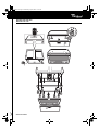
SCHEDA PRODOTTO
1. Pannello comandi.
2. Filtri antigrasso (1 o 2 pezzi).
3. Plafoniera (AKR 772: lampade alogene).
4. Cornice supporto filtri antigrasso.
Per togliere e sostituire o lavare il filtro
antigrasso:
1. Scollegare la cappa dalla rete elettrica.
2. Togliere il filtro antigrasso sporco tirando la
maniglia prima verso dietro, poi verso il basso
(Fig. 1).
3. Dopo aver lavato il filtro antigrasso procedere nel
senso inverso per il montaggio assicurandosi che
esso copra l'intera superficie di aspirazione.
Sostituzione delle lampadine
1. Scollegare la cappa dalla rete elettrica.
2. Togliere il filtro antigrasso (Fig. 1) e rimuovere la
cornice supporto filtri antigrasso
(Fig. 2 - sequenza a-b).
3. Rimuovere la lampada da sostituire.
4. Usare solo lampade da 40 W max E14.
Per il modello AKR 772 prevedere lampade
alogene da 20 W (GU5.3 - Ø 50 mm).
5. Rimontare la cornice supporto filtri antigrasso.
Per montare o sostituire il filtro al
carbone:
1. Scollegare la cappa dalla rete elettrica.
2. Togliere il filtro antigrasso (Fig. 1) e rimuovere la
cornice supporto filtri antigrasso
(Fig. 2 - sequenza a-b).
3. Se i filtri al carbone sono già montati (uno o due
filtri, a seconda del modello in Vs. possesso,
montati a copertura delle griglie di protezione
della girante del motore) e devono essere
sostituiti girare la maniglia centrale (Fig. 3 - c)
in senso antiorario sino allo sbloccaggio degli
stessi.
4. Se i filtri al carbone non sono montati applicarli
a copertura delle griglie di protezione della
girante del motore (due griglie di protezione -
due filtri al carbone, una griglia di protezione -
un filtro al carbone) dopodiché girare la maniglia
centrale (Fig. 3 - c) dei filtri in senso orario.
5. Rimontare la cornice e il filtro antigrasso.
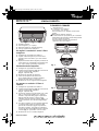
IL PANNELLO COMANDI
Interruttore luce.
Il tasto luce ha 2 posizioni
(luci spente - luci accese).
Per accendere le luci: spostare il tasto verso
destra.
Interruttore selezione velocità.
Il tasto motore ha più posizioni per il controllo
delle potenze di aspirazione in base alle quantita
di fumi e vapori da aspirare.
Per aumentare la potenza di aspirazione:
spostare il tasto verso destra.
Fig. 3
Fig. 1
Fig. 2
D F NL E
GB
P I GR
31833077.fm Page 11 Wednesday, April 9, 2003 11:13 AM
-
 1
1
-
 2
2
-
 3
3
-
 4
4


Whirlpool AKR 769 AV Program Chart
- Kategori
- Oyuncaklar
- Tip
- Program Chart
- Bu kılavuz aynı zamanda aşağıdakiler için de uygundur:
diğer dillerde
- español: Whirlpool AKR 769 AV
- italiano: Whirlpool AKR 769 AV
- Deutsch: Whirlpool AKR 769 AV
- English: Whirlpool AKR 769 AV
- Nederlands: Whirlpool AKR 769 AV
İlgili makaleler
-
Whirlpool AKR 772 GY Program Chart
-
-
-
-
-
Whirlpool AKR 770 GY Program Chart
-
Whirlpool AKR 959 IX Program Chart
-
-
-