
ISTRUZIONI PER L’INSTALLAZIONE E LA MANUTENZIONE
INSTRUCTIONS FOR INSTALLATION AND MAINTENANCE
INSTRUCTIONS POUR L’INSTALLATION ET L’ENTRETIEN
BEDIENUNGS- UND WARTUNGSANWEISUNGEN
GEBRUIKS- EN ONDERHOUDSAANWIJZINGEN
ИНСТРУКЦИИ ПО МОНТАЖУ И ТЕХОБСЛУЖИВАНИЮ
ASENNUS- JA HUOLTO-OHJEET
INSTALLATIONS - OCH UNDERHÅLLSANVISNING
INSTRUCTIUNI DE INSTALARE SI INTRETINERE
ΟΔΗΓΙΕΣ ΕΓΚΑΤΑΣΤΑΣΗΣ ΚΑΙ ΣΥΝΤΗΡΗΣΗΣ
INSTRUCCIONES PARA LA INSTALACIÓN Y EL MANTENIMIENTO
KURULUM VE BAKIM TALİMATI
INSTRUKCJA MONTAŻU I KONSERWACJI

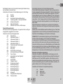
3’’
x4
+ +

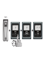
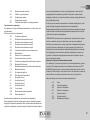
PUMP 1
5’’

PUMP 2
5’’

IT - ITALIANO pag 6
GB - ENGLISH page 12
FR - FRANÇAIS page 18
DE - DEUTSCH seite 24
NL - NEDERLANDS bladz 30
RU - РУССКИЙ стр. 36
FI - SUOMI sivu 42
SE - SVENSKA sida 48
RO - ROMANA pag. 54
GR - ΕΛΛΗΝΙΚΑ σελ. 60
ES - ESPAÑOL pág 66
TR - TÜRÇE say 72
PL - POLSKI str 78

ITALIANO
IT
6
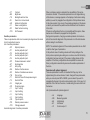
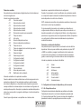
INDICE
1 Gruppi Multipli 4
1.1 Introduzione ai sistemi multi pompa 4
1.2 Realizzazione di un impianto multi pompa 4
1.3 Primo avvio sistema multi pompa 4
1.4 AS: Associazione dispositivi 4
1.5 Regolazione multi pompa 5
1.6 Assegnazione dell’ordine di partenza 6
1.7 Tempo massimo di lavoro 6
1.8 Raggiungimento del tempo massimo di inattività 6
1.9 Riserve e numero di dispositivi che partecipano al pompaggio 6
1.10 Parametri di interesse per il multi pompa 6
2. Impostazione del numero di dispositivi e delle riserve 8
2.1 NA: Dispositivi attivi 8
2.2 NC: Dispositivi contemporanei 8
2.3 IC: Congurazione della riserva 8
2.3.1 Esempi di congurazione per impianti multi pompa 8
2.4 ET: Tempo di scambio 9
1 - Gruppi Multipli
1.1 - Introduzione ai sistemi multi pompa
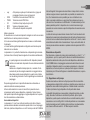
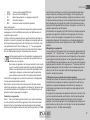
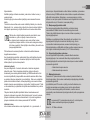
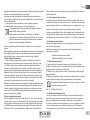
Per sistema multi pompa si intende un gruppo di pompaggio formato
da un insieme di pompe le cui mandate conuiscono su un collettore
comune. I dispositivi comunicano tra loro attraverso l’apposita connes-
sione (wireless).
Il numero massimo di dispositivi che si possono inserire a formare il
gruppo è 4.
Un sistema multi pompa viene utilizzato principalmente per:
• Aumentare le prestazioni idrauliche rispetto al singolo dispositivo
• Assicurare la continuità di funzionamento in caso di guasto ad
un dispositivo
• Frazionare la potenza massima
1.2 - Realizzazione di un impianto multi pompa
L’impianto idraulico deve essere realizzato in maniera più simmetrica
possibile per realizzare un carico idraulico uniformemente distribuito su
tutte le pompe.
Le pompe devono essere connesse tutte ad un unico collettore di mandata.
Per il buon funzionamento del gruppo di pressurizzazione
devono essere uguali per ogni dispositivo:
• i collegamenti idraulici
• la velocità massima
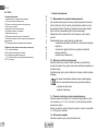
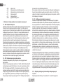
1.3 Primo avvio sistema multi pompa
Eseguire i collegamenti elettrici ed idraulici di tutto il sistema come de-
scritto al par 2.1.1, 2.2.1 e al par 3.1. (vedi Istruzione per l’installazione e
la manutenzione e.sybox)
Accendere i dispositivi e creare le associazioni come descritto al para-
grafo 1.6 - AS: Associazione dispositivi.
1.4 - AS: Associazione dispositivi
Permette di entrare in modalità connessione/disconnessione con i
seguenti dispositivi:

ITALIANO
IT
7
• e.sy Altra pompa e.sybox per funzionamento in gruppo di
pompaggio formato al max da 4 elementi
• COM Centralina di comunicazione PWM Com
• TERM Terminale remoto PWM Term
• I/O Centralina di input output e.sybox I/O
• RPR Sensore di pressione remoto
• DEV Altri eventuali dispositivi compatibili
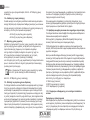
Menù connessioni
Si visualizzano le icone dei vari dispositivi collegati con sotto un acronimo
identicativo e la relativa potenza di ricezione.
Un’ icona accesa ssa signica dispositivo connesso e correttamente
funzionante;
un’ icona barrata signica dispositivo congurato come facente parte
della rete ma non rilevato.
La pressione di +/- permette di selezionare un dispositivo già connesso
(funzione attiva al rilascio) facendo apparire l’icona relativa sottolineata;
In questa pagina non si visualizzano tutti i dispositivi presenti
nell’etere ma solamente i dispositivi che sono stati associati alla
nostra rete.
Vedere solo i dispositivi della propria rete, consente il funzi-
onamento di più reti analoghe coesistenti nel raggio d’azione
del wireless senza creare ambiguità, in questo modo l’utente
non visualizza gli elementi che non appartengono al sistema di
pompaggio.
Da questa pagina di menù si permette di associare e dissociare un
elemento dalla rete wireless personale.
All’avvio della macchina la voce di menù AS non presenta alcuna
connessione perché nessun dispositivo è associato. Solo un’azione
dell’operatore permette di aggiungere o togliere dispositivi con le opera-
zioni di associazione e dissociazione.
Associazione dispositivi
La pressione di ‘+’ per 5 sec mette la macchina nello stato di ricerca
per associazione wireless comunicando questo stato con un lampeggio
dell’icona (relativa al dispositivo su cui si fa l’azione) e del led COMM ad
ITALIANO
IT
intervalli regolari. Non appena due macchine in campo utile di comuni-
cazione vengono messe in questo stato, se possibile, si associano tra
loro. Se l’associazione non è possibile per una o entrambe le mac-
chine, la procedura termina e su ogni macchina compare una pop up
che comunica “associazione non effettuabile”. Un’associazione può non
essere possibile perché il dispositivo che si cerca di associare è già
presente nel numero massimo o perché il dispositivo da associare non è
riconosciuto.
Lo stato di ricerca per associazione rimane attivo no al rilevamento del
dispositivo da associare (indipendentemente dall’esito dell’associazione);
se non si riesce a vedere nessun dispositivo nell’arco di 1 minuto, si esce
automaticamente dallo stato di associazione. Si può uscire dallo stato di
ricerca per associazione wireless in qualsiasi momento premendo SET o
MODE.
Dissociazione dispositivi
Per dissociare un elemento si deve prima selezionarlo con i tasti “+” o “-”,
poi premere – per 5 s; questo porta il sistema in modalità dissociazione
dispositivo selezionato nella quale l’icona del dispositivo evidenziato e
il led COMM iniziano a lampeggiare velocemente ad indicare che sarà
cancellato il dispositivo scelto. La successiva pressione di – dissocia il
dispositivo, se invece si preme un qualunque tasto oppure si lasciano
trascorrere più di 30 sec dall’ingresso in modalità dissociazione, la proce-
dura termina.
1.5 - Regolazione multi pompa
Quando si accende un sistema multi pompa viene fatto in automatico
un’assegnazione degli indirizzi e tramite un algoritmo viene nominato un
dispositivo come leader della regolazione. Il leader decide la velocità e
l’ordine di partenza di ogni dispositivo che fa parte della catena.
La modalità di regolazione è sequenziale (i dispositivi partono uno alla
volta). Quando si vericano le condizioni di partenza, parte il primo
dispositivo, quando questo è arrivato alla sua velocità massima, parte il
successivo e così via tutti gli altri. L’ordine di partenza non è necessaria-
mente crescente secondo l’indirizzo della macchina, ma dipende dalle
ore di lavoro effettuate vedi 2.4 - ET: Max tempo di scambio.

ITALIANO
IT
8
1.6 - Assegnazione dell’ordine di partenza
Ad ogni accensione del sistema viene associato ad ogni dispositivo un
ordine di partenza. In base a questo si generano le partenze in succes-
sione dei dispositivi.
L’ordine di partenza viene modicato durante l’utilizzo secondo la neces-
sità da parte dei due algoritmi seguenti:
• Raggiungimento del tempo massimo di lavoro
• Raggiungimento del tempo massimo di inattività
1.7 - Tempo massimo di lavoro
In base al parametro ET (tempo massimo di lavoro), ogni dispositivo ha
un contatore del tempo di lavoro, ed in base a questo si aggiorna l’ordine
di ripartenza secondo il seguente algoritmo:
se si è superato almeno metà del valore di ET si attua lo scambio di prior-
ità al primo spegnimento dell’inverter (scambio allo standby).
se si raggiunge il valore di ET senza mai arrestarsi, si spegne incondizio-
natamente l’inverter e si porta questo alla priorità minima di ripartenza
(scambio durante la marcia).
Se il parametro ET (tempo massimo di lavoro), è posto a 0, si
ha lo scambio ad ogni ripartenza.
Vedi 2.4 - ET: Max tempo di scambio.
1.8 - Raggiungimento del tempo massimo di inattività
Il sistema multi pompa dispone di un algoritmo di antiristagno che ha
come obiettivo quello di mantenere in perfetta efcienza le pompe e
mantenere l’integrità del liquido pompato. Funziona permettendo una ro-
tazione nell’ordine di pompaggio in modo da far erogare a tutte le pompe
almeno un minuto di usso ogni 23 ore. Questo avviene qualunque sia
la congurazione del dispositivo (enable o riserva). Lo scambio di priorità
prevede che il dispositivo fermo da 23 ore venga portato a priorità massi-
ma nell’ordine di partenza. Questo comporta che appena si renda neces-
sario l’erogazione di usso sia il primo ad avviarsi. I dispositivi congurati
come riserva hanno la precedenza sugli altri. L’algoritmo termina la sua
azione quando il dispositivo ha erogato almeno un minuto di usso.
Terminato l’intervento dell’antiristagno, se il dispositivo è congurato
come riserva, viene riportato a priorità minima in modo da preservarsi
dall’usura.
1.9 - Riserve e numero di dispositivi che partecipano al pompaggio
Il sistema multi pompa legge quanti elementi sono connessi in comunica-
zione e chiama questo numero N.
In base poi ai parametri NA ed NC decide quanti e quali dispositivi
devono lavorare ad un certo istante.
NA rappresenta il numero di dispositivi che partecipano al pompaggio.
NC rappresenta il massimo numero di dispositivi che possono lavorare
contemporaneamente.
Se in una catena ci sono NA dispositivi attivi e NC dispositivi contempo-
ranei con NC minore di NA signica che al massimo partiranno contem-
poraneamente NC dispositivi e che questi dispositivi si scambieranno tra
NA elementi. Se un dispositivo è congurato come preferenza di riserva,
sarà messo per ultimo come ordine di partenza, quindi se ad esempio ho
3 dispositivi e uno di questi congurato come riserva, la riserva partirà per
terzo elemento, se invece imposto NA=2 la riserva non partirà a meno
che uno dei due attivi non vada in fault.
Vedi anche la spiegazione dei parametri
2.1 - NA: Dispositivi attivi;
2.2 NC: Dispositivi contemporanei;
2.3 IC: Congurazione della riserva.
1.10 Parametri di interesse per il multi pompa
Parametri con signicato locale
Sono parametri che possono essere diversi tra i vari dispositivi ed in
alcuni casi è proprio necessario che siano diversi. Per questi parametri
non è permesso allineare automaticamente la congurazione tra i vari
dispositivi. Nel caso ad esempio di assegnazione manuale degli indirizzi,
questi dovranno obbligatoriamente essere diversi l’uno dall’altro.
Elenco dei parametri con signicato locale al dispositivo:
• CT Contrasto
• BK Luminosità

ITALIANO
IT
9
• TK Tempo di accensione retroilluminazione
• RI Giri/min in modalità manuale
• AD Congurazione indirizzo
• IC Congurazione riserva
• RF Azzeramento fault e warning
Parametri sensibili
Sono dei parametri che devono necessariamente essere allineati su tutta
la catena per ragioni di regolazione.
Elenco dei parametri sensibili:
• SP Pressione di Setpoint
• P1 Setpoint ausiliario ingresso 1
• P2 Setpoint ausiliario ingresso 2
• P3 Setpoint ausiliario ingresso 3
• P4 Setpoint ausiliario ingresso 4
• RP Diminuzione di pressione per ripartenza
• ET Tempo di scambio
• AY Anticycling
• NA Numero di dispositivi attivi
• NC Numero di dispositivi contemporanei
• TB Tempo di dry run
• T1 Tempo di spegnimento dopo il segnale
bassa pressione
• T2 Tempo di spegnimento
• GI Guadagno integrale
• GP Guadagno proporzionale
• I1 Impostazione ingresso 1
• I2 Impostazione ingresso 2
• I3 Impostazione ingresso 3
• I4 Impostazione ingresso 4
• OD Tipo di impianto
• PR Sensore di pressione Remoto
• PW Modica password
Allineamento automatico dei parametri sensibili
Quando viene rilevato un sistema multi pompa, viene fatto un controllo
sulla congruenza dei parametri impostati. Se i parametri sensibili non
sono allineati tra tutti i dispositivi, sul display di ogni dispositivo compare
un messaggio in cui si chiede se si desidera propagare a tutto il sistema
la congurazione di quel particolare dispositivo. Accettando, i parametri
sensibili del dispositivo su cui si è risposto alla domanda, vengono distri-
buiti a tutti i dispositivi della catena.
Nei casi in cui ci siano congurazioni incompatibili con il sistema, non si
consente da questi dispositivi la propagazione della congurazione.
Durante il normale funzionamento, la modica di un parametro sensibile
su un dispositivo, comporta l’allineamento automatico del parametro su
tutti gli altri dispositivi senza richiedere conferma.
NOTA: L’allineamento automatico dei parametri sensibili non ha alcun
effetto su tutti gli altri tipi di parametri.
Nel caso particolare di inserzione nella catena di un dispositivo con
impostazioni di fabbrica (caso di un dispositivo che sostituisce uno
esistente oppure un dispositivo che esce da un ripristino della congura-
zione di fabbrica), se le congurazioni presenti eccetto le congurazioni
di fabbrica sono congruenti, il dispositivo con congurazione di fabbrica
assume automaticamente i parametri sensibili della catena.
Parametri con allineamento facoltativo
Sono parametri per i quali si tollera che possano essere non allineati
tra i diversi dispositivi. Ad ogni modica di questi parametri, arrivati alla
pressione di SET o MODE, si chiede se propagare la modica all’intera
catena in comunicazione. In questo modo se la catena è uguale in tutti
suoi elementi, si evita di impostare gli stessi dati su tutti i dispositivi.
Elenco dei parametri con allineamento facoltativo:
• LA Lingua
• MS Sistema di misura
• AE Antibloccaggio
• AF AntiFreeze
• O1 Funzione uscita 1
• O2 Funzione uscita 2
• RM Velocità Massima

ITALIANO
IT
10
2 - Impostazione del numero di dispositivi e delle riserve
2.1 - NA: Dispositivi attivi
Imposta il numero massimo di dispositivi che partecipano al pompaggio.
Può assumere valori tra 1 e ed il numero di dispositivi presenti (max 4). Il
valore di default per NA è N, cioè il numero dei dispositivi presenti nella
catena; questo signica che se si inseriscono o si tolgono dispositivi dalla
catena, NA assume sempre il valore pari al numero di dispositivi presenti
rilevati automaticamente. Impostando un valore diverso da N si ssa sul
numero impostato il massimo numero di dispositivi che possono parte-
cipare al pompaggio.
Questo parametro serve nei casi in cui si abbia un limite di pompe da
potere o voler tenere accese e nel caso ci si voglia preservare uno o più
dispositivi come riserva (vedi 2.3 IC: Congurazione della riserva e gli
esempi a seguire).
In questa stessa pagina di menù si possono vedere (senza poterli modi-
care) anche gli altri due parametri del sistema legati a questo, cioè N,
numero di dispositivi presenti rilevato in automatico dal sistema, e NC,
numero massimo di dispositivi contemporanei.
2.2 NC: Dispositivi contemporanei
Imposta il numero massimo di dispositivi che possono lavorare contem-
poraneamente.
Può assumere valori tra 1 e NA. Come default NC assume il valore NA,
questo signica che comunque cresca NA, NC assume il valore di NA.
Impostando un valore diverso da NA ci si svincola da NA e si ssa sul nu-
mero impostato il massimo numero di dispositivi contemporanei. Questo
parametro serve nei casi in cui si ha un limite di pompe da potere o voler
tenere accese (vedi 2.3 IC: Congurazione della riserva e gli esempi a
seguire).
In questa stessa pagina di menù si possono vedere (senza poterli
modicare) anche gli altri due parametri del sistema legati a questo cioè
N, numero di dispositivi presenti letto in automatico dal sistema e NA,
numero di dispositivi attivi.
2.3 IC: Congurazione della riserva
Congura il dispositivo come automatico o riserva. Se impostato su auto
(default) il dispositivo partecipa al normale pompaggio, se congurato
come riserva, gli viene associato la minima priorità di partenza, ovvero il
dispositivo su cui si effettua tale impostazione partirà sempre per ultimo.
Se si imposta un numero di dispositivi attivi inferiore di uno rispetto al
numero di dispositivi presenti e si imposta un elemento come riserva,
l’effetto che si realizza è che se non ci sono inconvenienti, il dispositivo
riserva non partecipa al regolare pompaggio, nel caso invece uno dei
dispositivi che partecipano al pompaggio abbia un guasto (può essere
la mancanza di alimentazione, l’intervento di una protezione etc), parte il
dispositivo di riserva.
Lo stato di congurazione riserva è visibile nei seguenti modi: nella
pagina Sistema Multi pompa, la parte superiore dell’icona compare color-
ata; nelle pagine AD e principale, l’icona della comunicazione rafgurante
l’indirizzo del dispositivo appare con il numero su sfondo colorato. I dis-
positivi congurati come riserva posso essere anche più di uno all’interno
di un sistema di pompaggio.
I dispositivi congurati come riserva anche se non partecipano al normale
pompaggio vengono comunque tenuti efcienti dall’algoritmo di anti
ristagno. L’algoritmo antiristagno provvede una volta ogni 23 ore a scam-
biare la priorità di partenza e far accumulare almeno un minuto continu-
ativo di erogazione del usso ad ogni dispositivo. Questo algoritmo mira
ad evitare il degrado dell’acqua all’interno della girante e mantenere
efcienti gli organi in movimento; è utile per tutti i dispositivi ed in parti-
colare per i dispositivi congurati come riserva che in condizioni normali
non lavorano.
2.3.1 - Esempi di congurazione per impianti multi pompa
Esempio 1:
Un gruppo di pompaggio composto da 2 dispositivi (N=2 rilevato au-
tomaticamente) di cui 1 impostato attivo (NA=1), uno contemporaneo
(NC=1 oppure NC=NA poiché NA=1 ) e uno come riserva (IC=riserva su
uno dei due dispositivi).
L’effetto che si avrà è il seguente: il dispositivo non congurato come
riserva partirà e lavorerà da solo (anche se non riesce a sostenere
il carico idraulico e la pressione realizzata è troppo bassa). Nel caso
questo abbia un guasto entra in funzione il dispositivo di riserva.

ITALIANO
IT
11
ITALIANO
IT
Esempio 2:
Un gruppo di pompaggio composto da 2 dispositivi (N=2 rilevato
automaticamente) in cui tutti i dispositivi sono attivi e contemporanei (im-
postazioni di fabbrica NA=N e NC=NA) e uno come riserva (IC=riserva su
uno dei due dispositivi).
L’effetto che si avrà è il seguente: parte per primo sempre il dispositivo
che non è congurato come riserva, se la pressione realizzata è troppo
bassa parte anche il secondo dispositivo congurato come riserva. In
questo modo si cerca sempre e comunque di preservare l’utilizzo di un
dispositivo in particolare (quello congurato riserva), ma questo ci può
venire in soccorso in caso di necessità quando si presenta un carico
idraulico maggiore.
2.4 - ET: Max tempo di scambio
Imposta il tempo massimo di lavoro continuativo di un dispositivo
all’interno di un gruppo. Ha signicato solamente su gruppi di pompaggio
con dispositivi interconnessi tra loro. Il tempo può essere impostato tra
1min e 9 ore; l’impostazione di fabbrica è di 2 ore.
Quando il tempo ET di un dispositivo è scaduto si riassegna l’ordine
di partenza del sistema in modo da portare il dispositivo con il tempo
scaduto alla priorità minima. Questa strategia ha lo scopo di utilizzare di
meno il dispositivo che ha già lavorato ed equilibrare il tempo di lavoro tra
le varie macchine che compongono il gruppo. Se nonostante il disposi-
tivo sia stato messo all’ultimo posto come ordine di partenza, il carico
idraulico necessita comunque dell’intervento del dispositivo in questione,
questo partirà per garantire la pressurizzazione dell’impianto.
La priorità di partenza viene riassegnata in due condizioni in base al
tempo ET:
1- Scambio durante il pompaggio: quando la pompa sta accesa
ininterrottamente no al superamento del tempo massimo assoluto di
pompaggio.
2- Scambio allo standby: quando la pompa è in standby ma si
è superato il 50% del tempo ET.
Nel caso in cui venga impostato ET uguale 0, si ha lo scambio allo
standby. Ogni volta che una pompa del gruppo si ferma al successivo
riavvio partirà un pompa diversa.
Se il parametro ET (tempo massimo di lavoro), è posto a 0, si
ha lo scambio ad ogni ripartenza, indipendentemente dal tempo
di lavoro effettivo della pompa.

ENGLISH
GB
12
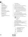
INDEX
1 Multiple Sets 10
1.1 Introduction to multipump systems 10
1.2 Making a multipump system 10
1.3 First start of the multipump system 10
1.4 AS: Association of devices 10
1.5 Multipump adjustment 11
1.6 Assigning the starting order 12
1.7 Maximum work time 12
1.8 Reaching the maximum inactivity time 12
1.9 Reserves and number of devices that participate in pumping 12
1.10 Parameters linked to multipump operation 12
2 Setting the number of devices and of reserves 14
2.1 NA: Active devices 14
2.2 NC: Simultaneous devices 14
2.3 IC: Conguration of the reserve 14
2.3.1 Examples of conguration for multipump systems 14
2.4 ET: Exchange time 15
1 - Multiple Sets
1.1 - Introduction to multipump systems
By multipump systems we mean a pump set made up of a number of
pumps whose deliveries all ow into a common manifold. The devices
communicate with one another by means of the connection provided
(wireless).
The group may be made up of a maximum of 4 devices.
A multipump system is used mainly for:
• Increasing hydraulic performance in comparison with a single
device
• Ensuring continuity of operation in the event of a device devel-
oping a fault
• Sharing out the maximum power
1.2 - Making a multipump system
The hydraulic plant must be created as symmetrically as possible to
obtain a hydraulic load uniformly distributed over all the pumps.
The pumps must all be connected to a single delivery manifold:
For good operation of the pressure boosting set, the following
must be the same for each device:
• hydraulic connections
• maximum speed
1.3 First start of the multipump system
Make the electric and hydraulic connections of the whole system as
described in par 2.1.1, 2.2.1 and par 3.1. (see Instructions for installation
and maintenance e.sybox).
Switch on the devices and create the associations as described in para-
graph 1.4 – AS: Association of devices.
1.4 - AS: Association of devices
Allows connection/disconnection with the following devices
• e.sy Other e.sybox pump for operation in a pump set
• composed of max 4 elements

ENGLISH
GB
13
• COM PWM Com communication control unit
• TERM PWM Term remote control terminal
• I/O e.sybox I/O input output control unit
• RPR Remote pressure sensor
• DEV Any other compatible devices
Connections menu
The icons of the various connected devices are displayed with below an
identifying acronym and the respective reception power.
An icon lit with a xed light means that the device is connected and work-
ing correctly; a stroked through icon means the device is congured as
part of the network but is not found.
Pressing “+” or “-” allows you to select a device that is already connected
(function active on release) making the respective icon appear in reverse;
when the device is selected, a description of the selected device appears
underlined.
All the devices present over the air are not displayed on this
page but only the devices that have been associated with our
network.
Seeing only the devices in your own network allows the opera-
tion of several similar networks existing within the radius of
action of the wireless without creating ambiguity; in this way
the user does not see the elements that do not belong to his
pumping system.
From this menu page it is possible to associate and disassociate an ele-
ment from your personal wireless network.
When the machine starts the AS menu item does not show any connec-
tion because no device is associated. Only an action by the operator can
allow devices to be added or removed with the operations of association
and disassociation.
Association of devices
Pressing ‘+’ for 5 sec puts the machine into the mode where it searches
for wireless association, communicating this status by the blinking of the
icon (related to the device on which the action is carried out) and of the
ENGLISH
GB
COMM leds at regular intervals. As soon as two machines in a working
communication range are put into this status, if possible, they are associ-
ated with each other. If the association is not possible for one or both
machines, the procedure ends and a pop-up appears on each machine
saying “association not possible”. An association may not be possible
because the device you are trying to associate is already present in the
maximum number or because the device to be associated is not recog-
nised.
The search status for association remains active until the device to be
associated is detected (irrespective of the result of association); if not
device can be seen within the space of 1 minutes, the machine auto-
matically leaves association status. You can leave the search status for
wireless association at any time by pressing SET or MODE.
Disassociation of devices
To disassociate an element you must rst select it with the “+” or “-” keys,
then press - for 5 s; this puts the system into device disassociation mode
in which the icon of the selected device and the COMM led start to ash
rapidly, indicating that the device chosen will be cancelled. The next time
- is pressed the device will be disassociated; instead, if you press any
key or let more than 30 sec elapse from entering disassociation mode,
the procedure will be terminated.
1.5 Multipump adjustment
When a multipump system is switched on, the addresses are automati-
cally assigned and an algorithm selects one device as the adjustment
leader. The leader decides the speed and starting order of each device in
the chain.
The adjustment mode is sequential (the devices start one at a time).
When starting conditions occur, the rst device starts, when it has
reached maximum speed the next one starts, and then the others in
sequence. The starting order is not necessarily in ascending order ac-
cording to the machine address, but it depends on the working hours
done see 2.4 - ET: Max. switching time

ENGLISH
GB
14
1.6 - Assigning the starting order
Each time the system is switched on a starting order is associated with
each device. Depending on this, the sequential starts of the devices are
decided.
The starting order is modied during use as necessary by the following
two algorithms:
• Reaching the maximum work time
• Reaching the maximum inactivity time
1.7 - Maximum work time
Depending on the parameter ET (maximum work time), each device
has a working time counter, and depending on this the starting order is
updated with the following algorithm:
- if at least half of the ET value has been exceeded, the priority
is exchanged the rst time the inverter switches off (exchange
to standby).
- if the ET value is reached without ever stopping, the inverter is
switched off unconditionally and is taken to minimum restarting
priority (exchange during running).
If the parameter ET (maximum work time) is set at 0, there is an
exchange at each restart.
See 2.4 - ET: Max. switching time.
1.8 - Reaching the maximum inactivity time
The multipump system has an anti-stagnation algorithm, the aim of which
is to keep the pumps in perfect working order and to maintain the integrity
of the pumped uid. It works by allowing a rotation in the pumping order
so as to make all the pumps supply at least one minute of ow every
23 hours. This happens whatever the device conguration (enabled or
reserve). The exchange of priority requires that the device that has been
stopped for 23 hours be given maximum priority in the starting order. This
means that as soon as it is necessary to supply ow, it will be the rst to
start. The devices congured as reserve have precedence over the oth-
ers. The algorithm ends its action when the device has supplied at least
one minute of ow.
When the intervention of the anti-stagnation algorithm is over, if the
device is congured as reserve, it is returned to minimum priority to
preserve it from wear.
1.9 - Reserves and number of devices that participate in pumping
The multipump system reads how many elements are connected in com-
munication and calls this number N.
Then depending on the parameters NA and NC it decides how many and
which devices must work at a certain time.
NA represents the number of devices that participate in pumping. NC rep-
resents the maximum number of devices that can work at the same time.
If there are NA active devices in a chain and NC simultaneous devices
with NC smaller than NA, it means that at the most NC devices will start
at the same time and that these devices will exchange with NA elements.
If a device is congured with reserve preference, it will be the last in the
starting order, so for example if I have 3 devices and one of these is con-
gured as reserve, the reserve will be the third element to start, whereas
if I set NA=2 the reserve will not start unless one of the two active ones
develops a fault.
See also the explanation of the parameters
2.1 - NA: Active devices;
2.2 NC: Simultaneous devices;
2.3 IC: Conguration of the reserve.
1.10 Parameters concerning multipump
Parameters with local signicance
These are parameters that can be divided among the various devices and
in some cases it is necessary for them to be different. For these param-
eters it is not allowed to align the conguration automatically among the
various devices. For example, in the case of manual assignment of the
addresses, these must absolutely be different one from the other.
List of parameters with local signicance for the device:

ENGLISH
GB
15
• CT Contrast
• BK Brightness
• TK Backlight switch-on time
• RI Revs/min in manual mode
• AD Address Conguration
• IC Reserve conguration
• RF Reset fault and warning
• PW Set Password
Sensitive parameters
These are parameters which must necessarily be aligned over the whole
chain for adjustment reasons.
List of sensitive parameters:
• SP Setpoint pressure
• P1 Auxiliary setpoint input 1
• P2 Auxiliary setpoint input 2
• P3 Auxiliary setpoint input 3
• P4 Auxiliary setpoint input 4
• RP Pressure decrease to restart
• ET Exchange time
• AY Anticycling
• NA Number of active devices
• NC Number of simultaneous devices
• TB Dry run time
• T1 Switch-off time after low pressure signal
• T2 Switch-off time
• GI Integral gain
• GP Proportional gain
• I1 Input 1 setting
• I2 Input 2 setting
• I3 Input 3 setting
• I4 Input 4 setting
• OD Type of system
• PR Remote pressure sensor
• PW Change password
Automatic alignment of sensitive parameters
When a multipump system is detected, the compatibility of the set pa-
rameters is checked. If the sensitive parameters are not aligned among
all the devices, a message appears on the display of each device asking
whether you want to propagate the conguration of that particular device
to the whole system. If you accept, the sensitive parameters of the device
on which you answered the question will be distributed to all the devices
in the chain.
If there are congurations that are not compatible with the system, these
devices are not allowed to propagate their conguration.
During normal operation, changing a sensitive parameter of a device re-
sults in the automatic alignment of the parameter on all the other devices
without asking for conrmation.
NOTE: The automatic alignment of the sensitive parameters has no effect
on all the other types of parameters.
In the particular case of inserting a device with factory settings in the
chain (a device replacing an existing one or a device on which the factory
conguration has been restored), if the present congurations with the
exception of the factory congurations are compatible, the device with
factory conguration automatically assumes the sensitive parameters of
the chain.
Parameters with optional alignment
These are parameters for which it is tolerated that they may not be
aligned among the various devices. At each change of these parameters,
when you come to press SET or MODE, you are asked if you want to
propagate the change to the entire communication chain. In this way, if all
elements of the chain are the same, it avoids setting the same data on all
the devices
List of parameters with optional alignment:
• LA Language
• MS Measuring system
• AE Anti-blocking
• AF AntiFreeze
• O1 Function output 1

ENGLISH
GB
16
• O2 Function output 2
• RM Maximum speed
2 - Setting the number of devices and of reserves
2.1 - NA: Active devices
Sets the maximum number of devices that participate in pumping.
It may have values between 1 and the number of devices present (max
4). The default value for NA is N, that is the number of devices present
in the chain; this means that if devices are added to or removed from
the chain, NA always has the value of the number of devices present,
automatically detected. If a number different from N is set, this xes
the maximum number of devices that can participate in pumping at the
number set.
This parameter is used in cases where there is a limit on the pumps you
can or want to be able to keep running, and if you want to keep one or
more devices as a reserve (see 2.3 IC: Conguration of the reserve and
other examples below).
On the same menu page you can also see (but not change) the other two
system parameters linked to this, that is N, the number of devices pres-
ent, acquired automatically by the system, and NC, the maximum number
of simultaneous devices.
2.2 NC: Simultaneous devices
Sets the maximum number of devices that can work at the same time.
It may have values between 1 and NA. The default value of NC is NA, this
means that even if NA increases, NC will have the value NA. If a number
different from NA is set, this releases you from NA and xes the maximum
number of simultaneous devices at the number set. This parameter is
used in cases where there is a limit on the pumps you can or want to be
able to keep running (see 2.3 IC: Conguration of the reserve and other
examples below).
On the same menu page you can also see (but not change) the other
two system parameters linked to this, that is N, the number of devices
present, read automatically by the system, and NA, the number of active
devices.
2.3 IC: Conguration of the reserve
Congures the device as automatic or reserve. If set on auto (default)
the device participates in normal pumping, if congured as reserves,
minimum starting priority is associated with it, this means that the device
with this setting will always start last. If a number of active devices is set
that is one lower than the number of devices present and if one element
is set as reserve, the effect obtained is that, if there are no problems, the
reserve device does not participate in regular pumping; instead, if one of
the devices that participates in pumping develops a fault (maybe loss of
power supply, tripping of a protection, etc.), the reserve device will start.
The state of conguration as a reserve can be seen as follows: on the
Multi-pump System page, the top of the icon is coloured; on the AD and
main pages, the communication icon representing the address of the
device appears with the number on a coloured background. There may
be more than one device congured as reserve in a pumping system.
Even though the devices congured as reserve do not participate in nor-
mal pumping, they are nevertheless kept efcient by the anti-stagnation
algorithm. The anti-stagnation algorithm changes the starting priority
once every 23 hours and allows the accumulation of at least one continu-
ous minute of supply of ow from each device. The aim of this algorithm
is to avoid the deterioration of the water inside the impeller and to keep
the moving parts efcient; it is useful for all devices and especially for
those congured as reserve, which do not work in normal conditions.
2.3.1 - Examples of conguration for multipump systems
Example 1:
A pump set composed of 2 devices (N=2 detected automatically) of which
1 set active (NA=1), one simultaneous (NC=1 or NC=NA since NA=1)
and one as reserve (IC=reserve on one of the two devices).
The result obtained is the following: the device not congured as a
reserve will start and work by itself (even though it does not manage to
bear the hydraulic load and the pressure achieved is too low). If it has a
fault, the reserve device steps in.
Example 2:
A pump set composed of 2 devices (N=2 detected automatically) in which
all the devices are active and simultaneous (factory settings NA=N and

ENGLISH
GB
17
NC=NA) and one as reserve (IC=reserve on one of the two devices).
The result obtained is the following: the device that is not congured
as reserve always starts rst, if the pressure detected is too low the
second device, congured as reserve, also starts. In this way we always
try to preserve the use of one device in particular (the one congured
as reserve), but this may be useful in case of necessity when a greater
hydraulic load occurs.
2.4 - ET: Max. switching time
Sets the maximum continuous working time of a device in a set. It is
signicant only on pump sets with interconnected devices. The time can
be set between 1 min and 9 hours; the factory setting is 2 hours.
When the ET of a device has elapsed the system starting order is reas-
signed so as to give minimum priority to the device on which the time
has elapsed. The aim of this strategy is to use less the device that has
already worked and to balance the working time between the various
machines that make up the set. If the hydraulic load still requires the in-
tervention of the device, even though it has been put last in starting order,
it will start to guarantee pressure boosting of the system.
The starting priority is reassigned in two conditions based on the ET time:
1. Exchange during pumping: when the pump remains on without
interruption until the absolute maximum pumping time has been
exceeded
2. Exchange to standby: when the pump is on standby but 50% of the
ET time has been exceeded
If ET has been set at 0 there will be exchange to standby. Whenever
a pump in the set stops, a different pump will start rst next time it is
restarted.
If the parameter ET (maximum work time) is set at 0, there will
be exchange at each restart, irrespective of the pump’s actual
work time.

FRANÇAIS
FR
18
SOMMAIRE
1 Groupes multiples 16
1.1 Introduction au système à pompes multiples 16
1.2 Réalisation d’un système à pompes multiples 16
1.3 Premier démarrage du système à pompes multiples 16
1.4 AS: Association de dispositifs 16
1.5 Réglage du système à pompes multiples 17
1.6 Attribution de l’ordre de démarrage 17
1.7 Temps de travail maximum 18
1.8 Atteinte du temps d’inactivité maximum 18
1.9 Réserves et nombre de dispositifs participant au pompage 18
1.10 Paramètres d’intérêt pour le système à pompes multiples 18
2 Réglage du nombre de dispositifs et des réserves 20
2.1 NA : Dispositifs actifs 20
2.2 NC : Dispositifs simultanés 20
2.3 IC : Conguration de la réserve 20
2.3.1: Exemples de conguration pour les systèmes à pompes multiples 20
2.4 ET : Temps d’échange 21
1 - Groupes multiples
1.1 - Introduction au système à pompes multiples
L’on entend par système à pompes multiples un groupe de pompage
formé d’un ensemble de pompes dont les distributions conuent sur un
collecteur commun. Les dispositifs communiquent entre eux à travers la
connexion prévue (sans l).
Le nombre maximum de dispositifs pouvant former un groupe est de 4.
Un système à pompes multiples est principalement utilisé pour :
• Augmenter les prestations hydrauliques par rapport au dispositif simple
• Assurer la continuité du fonctionnement en cas de panne d’un dispositif
• Fractionner la puissance maximum
1.2 - Réalisation d’un système à pompes multiples
L’installation hydraulique doit être réalisée de la manière la plus symétrique
possible, an de réaliser une charge hydraulique répartie de manière uni-
forme sur toutes les pompes.
Les pompes doivent toutes être reliées à un seul collecteur de distribution.
Pour le bon fonctionnement du groupe de pressurisation, tout le
dispositif doit comprendre les mêmes:
• branchements hydrauliques
• vitesse maximale
1.3 - Premier démarrage du système à pompes multiples
Effectuer les branchements électriques et hydrauliques de tout le système
suivant les indications des parag. 2.1.1, 2.2.1 et 3.1. (voir Instructions pour
l’installation et l’entretien e.sybox). 1.4 AS : Association de dispositifs.
1.4 - AS: Association de dispositifs
Permet d’entrer en modalité connexion/déconnexion avec les
dispositifs suivants:
• e.sy Autre pompe e.sybox pour le fonctionnement en
groupe de pompage formé de 4 éléments au maximum
• COM Centrale de communication PWM Com
• TERM Terminal distant PWM Term

FRANÇAIS
FR
19
• I/O Centrale d’entrée/sortie e.sybox I/O
• RPR Capteur de pression distant
• DEV Autres dispositifs compatibles éventuels
Menu connexions
Les icônes des différents dispositifs branchés sont afchées. Sous
celles-ci gurent un acronyme identicateur et la puissance de
réception pertinente.
Une icône allumée xe indique que le dispositif branché fonctionne
correctement; une icône barrée indique que le dispositif est conguré
comme faisant partie du réseau mais que sa présence n’est pas relevée.
La pression de +/- permet de sélectionner un dispositif déjà branché (fonction
active au relâchement) et afche l’icône qui y correspond soulignée;
Cette page n’afche pas tous les dispositifs présents, mais
uniquement ceux qui sont associés à notre réseau.
Le fait de ne voir que les dispositifs de son propre réseau
permet de faire fonctionner plusieurs réseaux analogues
coexistants
dans le rayon d’action du système sans l sans créer
d’ambiguïté. Ainsi, l’utilisateur ne voit pas les dispositifs qui ne
correspondent pas au système de pompage.
Cette page de menu permet d’associer et de dissocier un élément du
réseau sans l personnel.
Lorsque la machine est démarrée, la mention du menu AS ne présente
aucune connexion, car aucun dispositif n’est associé. Seule une
action de l’opérateur permet d’ajouter ou d’éliminer des dispositifs par les
opérations d’association et de dissociation.
Association de dispositifs
La pression de « + » pendant 5 secondes met la machine en état de
recherche par association sans l. Cet état est indiqué par l’icône
(du dispositif sur lequel l’action est effectuée) et le DEL COMM cligno-
tants à intervalles réguliers. Dès que deux machines du champ de
communication utile sont mises dans cet état, si cela est possible elles
s’associent entre elles. Si l’association n’est pas possible pour
une machine ou pour les deux, la procédure se termine et une fenêtre
pop-up apparaît sur chaque machine, indiquant « association
non faisable ». Une association peut ne pas être possible car le dispositif
que l’on essaie d’associer est déjà présent dans le nombre
maximum ou parce que le dispositif à associer n’est pas reconnu.
L’état de recherche par association reste actif jusqu’au relevage du dis-
positif à associer (indépendamment du résultat de l’association) ;
si aucun dispositif n’est trouvé en 1 minute, le système sort automatique-
ment de l’état d’association. L’utilisateur peut sortir à tout moment
de l’état de recherche par association sans l en appuyant sur SET ou
MODE.
Dissociation de dispositifs
Pour dissocier un élément, il faut d’abord le sélectionner à l’aide des
touches « + » ou « - », puis appuyer sur - pendant 5 sec. ; cela porte
le système en modalité de dissociation du dispositif sélectionné. L’icône
du dispositif sélectionné et le DEL COMM commencent alors à
clignoter rapidement an d’indiquer que le dispositif choisi sera effacé. La
pression successive sur - dissocie le dispositif. En appuyant
sur une autre touche, quelle qu’elle soit, ou en laissant passer plus de 30
sec. à partir du moment de l’entrée en modalité dissociation, la
procédure est terminée.
1.5 - Réglage du système à pompes multiples
Lorsqu’un système à pompes multiples s’allume, l’attribution des adress-
es est effectuée automatiquement et un algorithme nomme un dispositif
comme leader du réglage. Le leader décide la vitesse et l’ordre de départ
de chaque dispositif faisant partie de la chaîne.
La modalité de réglage est séquentielle (les dispositifs démarrent l’un
après l’autre). Lorsque les conditions de départ sont présentes le premier
dispositif démarre ; quand il arrive à sa vitesse maximale, le second
démarre, et ainsi de suite pour tous les suivants. L’ordre de départ n’est
pas nécessairement croissant en fonction de l’adresse de la machine,
mais il dépend des heures de travail effectuées. Voir le parag. 2.4 - ET :
Temps d’échange max.
1.6 - Attribution de l’ordre de démarrage

FRANÇAIS
FR
20
Un ordre de démarrage est attribué à chaque dispositif à chaque mise en
marche du système. La succession des démarrages des dispositifs est
générée en fonction de cela.
L’ordre de démarrage est modié durant l’utilisation en fonction du besoin
des algorithmes suivants:
• Atteinte du temps de travail maximum
• Atteinte du temps d’inactivité maximum
1.7 - Temps de travail maximum
En fonction du paramètre ET (temps de travail maximum), chaque dis-
positif a un contacteur de temps de travail, en fonction duquel l’ordre de
redémarrage est mis en jour suivant l’algorithme suivant:
si au moins la moitié de la valeur de ET est dépassée, l’échange de pri-
orité est effectué au premier arrêt de l’inverseur (échange en veille).
si la valeur de ET est atteinte sans.
Si le paramètre ET (temps de travail maximum) est sur 0,
l’échange a lieu à chaque remise en marche.
Voir 2.4 - ET : Temps d’échange max.
1.8 - Raggiungimento del tempo massimo di inattività
Le système à pompes multiples dispose d’un algorithme anti-stase qui a
pour objectif de maintenir les pompes en état d’efcacité parfaite et de
maintenir l’intégrité du liquide pompé. Il fonctionne en permettant une
rotation de l’ordre de pompage de telle manière que toutes les pompes
distribuent au moins une minute de débit toutes les 23 heures. Cela
advient quelle que soit la conguration du dispositif (activé ou réserve).
L’échange de priorité prévoit que le dispositif arrêté depuis 23 heures soit
porté à une priorité maximum dans l’ordre de démarrage. Cela implique
qu’il démarre le premier dès que la distribution de débit est nécessaire.
Les dispositifs congurés comme réserve ont la priorité sur les autres.
L’algorithme termine son action lorsque le dispositif a distribué le débit
pendant au moins une minute.
Au terme de l’intervention de l’anti-stase, si le dispositif est conguré
comme réserve, il est ramené à la priorité minimale an d’être préservé
de l’usure.
1.9 - Réserves et nombre de dispositifs participant au pompage
Le système à pompes multiples lit le nombre d’éléments reliés en com-
munication et appelle ce nombre N.
Ensuite, en fonction des paramètres NA et NC, il décide combien de
dispositifs, et lesquels, doivent travailler à un instant donné.
NA représente le nombre de dispositifs participant au pompage. NC
représente le nombre maximum de dispositifs pouvant travailler simul-
tanément.
Si une chaîne comprend NA dispositifs actifs et NC dispositifs simul-
tanés dont le NC est inférieur à NA, cela entend que NC dispositifs au
maximum démarreront et que ces dispositifs s’échangeront entre NA élé-
ments. Si un dispositif est conguré comme préférence de réserve, il sera
placé en dernier dans l’ordre de démarrage. Ainsi, si l’on dispose de 3
dispositifs dont un est conguré comme réserve, la réserve démarrera le
troisième. Au contraire, si NA=2 est paramétré, la réserve ne démarrera
pas, sauf si l’un des deux éléments actifs sera en panne.
Voir également l’explication des paramètres
2.1 - NA : Dispositifs actifs;
2.2 NC : Dispositifs simultanés;
2.3 IC : Conguration de la réserve.
1.10 Paramètres d’intérêt pour le système à pompes multiples
Paramètres à signication locale
Il s’agit de paramètres qui peuvent être différents suivant les différents
dispositifs. Dans certains cas, il est nécessaire qu’ils soient différents.
Pour ces paramètres, il n’est pas permis d’aligner automatiquement
la conguration des différents dispositifs. Par exemple, dans le cas de
l’attribution manuelle des adresses, ils devront obligatoirement être dif-
férents les uns des autres.
Liste des paramètres avec leur signication locale pour le dispositi:
• CT Contraste
• BK Luminosité
• TK Temps d’allumage de l’éclairage de fond
Sayfa yükleniyor...
Sayfa yükleniyor...
Sayfa yükleniyor...
Sayfa yükleniyor...
Sayfa yükleniyor...
Sayfa yükleniyor...
Sayfa yükleniyor...
Sayfa yükleniyor...
Sayfa yükleniyor...
Sayfa yükleniyor...
Sayfa yükleniyor...
Sayfa yükleniyor...
Sayfa yükleniyor...
Sayfa yükleniyor...
Sayfa yükleniyor...
Sayfa yükleniyor...
Sayfa yükleniyor...
Sayfa yükleniyor...
Sayfa yükleniyor...
Sayfa yükleniyor...
Sayfa yükleniyor...
Sayfa yükleniyor...
Sayfa yükleniyor...
Sayfa yükleniyor...
Sayfa yükleniyor...
Sayfa yükleniyor...
Sayfa yükleniyor...
Sayfa yükleniyor...
Sayfa yükleniyor...
Sayfa yükleniyor...
Sayfa yükleniyor...
Sayfa yükleniyor...
Sayfa yükleniyor...
Sayfa yükleniyor...
Sayfa yükleniyor...
Sayfa yükleniyor...
Sayfa yükleniyor...
Sayfa yükleniyor...
Sayfa yükleniyor...
Sayfa yükleniyor...
Sayfa yükleniyor...
Sayfa yükleniyor...
Sayfa yükleniyor...
Sayfa yükleniyor...
Sayfa yükleniyor...
Sayfa yükleniyor...
Sayfa yükleniyor...
Sayfa yükleniyor...
Sayfa yükleniyor...
Sayfa yükleniyor...
Sayfa yükleniyor...
Sayfa yükleniyor...
Sayfa yükleniyor...
Sayfa yükleniyor...
Sayfa yükleniyor...
Sayfa yükleniyor...
Sayfa yükleniyor...
Sayfa yükleniyor...
Sayfa yükleniyor...
Sayfa yükleniyor...
Sayfa yükleniyor...
Sayfa yükleniyor...
Sayfa yükleniyor...
Sayfa yükleniyor...
-
 1
1
-
 2
2
-
 3
3
-
 4
4
-
 5
5
-
 6
6
-
 7
7
-
 8
8
-
 9
9
-
 10
10
-
 11
11
-
 12
12
-
 13
13
-
 14
14
-
 15
15
-
 16
16
-
 17
17
-
 18
18
-
 19
19
-
 20
20
-
 21
21
-
 22
22
-
 23
23
-
 24
24
-
 25
25
-
 26
26
-
 27
27
-
 28
28
-
 29
29
-
 30
30
-
 31
31
-
 32
32
-
 33
33
-
 34
34
-
 35
35
-
 36
36
-
 37
37
-
 38
38
-
 39
39
-
 40
40
-
 41
41
-
 42
42
-
 43
43
-
 44
44
-
 45
45
-
 46
46
-
 47
47
-
 48
48
-
 49
49
-
 50
50
-
 51
51
-
 52
52
-
 53
53
-
 54
54
-
 55
55
-
 56
56
-
 57
57
-
 58
58
-
 59
59
-
 60
60
-
 61
61
-
 62
62
-
 63
63
-
 64
64
-
 65
65
-
 66
66
-
 67
67
-
 68
68
-
 69
69
-
 70
70
-
 71
71
-
 72
72
-
 73
73
-
 74
74
-
 75
75
-
 76
76
-
 77
77
-
 78
78
-
 79
79
-
 80
80
-
 81
81
-
 82
82
-
 83
83
-
 84
84


DAB E.SYTWIN Kullanma talimatları
- Tip
- Kullanma talimatları
- Bu kılavuz aynı zamanda aşağıdakiler için de uygundur:
diğer dillerde
- français: DAB E.SYTWIN Mode d'emploi
- italiano: DAB E.SYTWIN Istruzioni per l'uso
- Deutsch: DAB E.SYTWIN Bedienungsanleitung
- Nederlands: DAB E.SYTWIN Handleiding
- română: DAB E.SYTWIN Instrucțiuni de utilizare
İlgili makaleler
-
DAB E.SYBOX Instruction For Installation And Maintenance
-
-
-
-
DAB ACTIVE J102 Instruction For Installation And Maintenance
-
-
-
-
-