Bauknecht DKE 3360 IN Program Chart
- Kategori
- Ocak davlumbazları
- Tip
- Program Chart

5019 100 75187
DKEL 3760-3790 / DKR 3760-3790
DKE 3360-3361-3390 / MSK 3760-3790
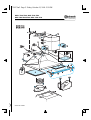
INSTALLATIONSANGABEN
Mindestabstand zur Kochfläche: 60 cm (Elektrokochplatten), 75 cm (Gas-, Öl-
oder Kohlekochplatten). Folgen Sie bei der Installation der Nummerierung
(1
Ö
2
Ö
3
Ö
.....)
. Das Auslassrohr (13A) wird nicht mitgeliefert und muss gesondert
erworben werden Das Gerät darf erst nach erfolgter Installation an die
Stromversorgung angeschlossen werden. Der Stecker der Dunstabzugshaube
muss mit einer normgerechten und gut zugänglichen Steckdose verbunden
werden. Wenn die Dunstabzugshaube nicht mit einem Stecker versehen ist
(direkter Netzanschluss), muss ein zweipoliger, normgerechter, gut zugänglicher
Schalter eingebaut werden, dessen Kontakte einen Abstand von mindestens
3 mm aufweisen.
Überprüfen Sie die korrekte Wandbefestigung der Dunstabzugshaube (8).
INSTALLATION SHEET
Minimum height above cooker: 60 cm (electric cookers), 75 cm (gas, gas oil or
coal cookers). To install follow points
(1
Ö
2
Ö
3
Ö
.....)
. The exhaust pipe (13A) is not
provided and should be bought separately. Do not connect the appliance to the
electrical power supply until installation is completed. The power plug of the
hood must be connected to a socket that complies with current regulations,
located in an easily accessible point. If the hood is not fitted with a plug (direct
connection to the power supply), fit a two-pole switch in compliance with
regulations, with minimum break distance between contacts of 3 mm (easily
accessible).
Ensure the hood is fitted to the wall (8).
FICHE D'INSTALLATION
Distance minimale par rapport à la cuisinière : 60 cm (cuisinière électrique), 75 cm
(cuisinière à gaz, mazout ou charbon). Pour le montage, suivez la numérotation
(1
Ö
2
Ö
3
Ö
.....)
. Le tuyau d'évacuation (13A) n'est pas fourni avec l'appareil et doit
être acheté à part. Ne branchez pas l'appareil tant que l'installation n'est pas
terminée. La fiche de la hotte doit être branchée dans une prise conforme aux
normes en vigueur, placée dans un endroit accessible. Si la hotte est branchée
sans fiche (branchement direct sur le réseau), appliquez un interrupteur bipolaire
conforme aux normes ayant une distance minimale de 3 mm entre les contacts
(accessible).
Assurez-vous d'avoir fixé la hotte à la paroi (8).
INSTALLATIEKAART
Minimumafstand tot het kooktoestel: 60 cm (elektrische kooktoestellen), 75 cm
(kooktoestellen op gas, olie of kolen). Volg voor de montage de nummering
(1
Ö
2
Ö
3
Ö
.....)
. De afvoerleiding (13A) wordt niet geleverd en dient aangeschaft te
worden. Geef het apparaat geen stroom totdat de installatie geheel voltooid is. De
stekker van de kap moet op een goed toegankelijk stopcontact aangesloten
worden dat aan de geldende veiligheidsvoorschriften voldoet. In het geval dat de
kap geen stekker heeft (directe aansluiting op het elektriciteitsnet) dient u een
tweepolige schakelaar te gebruiken met een afstand tussen de contacten van
minstens 3 mm (toegankelijk).
Controleer of de wasemkap aan de muur (8) is bevestigd.
D
GB
F
NL
75187.fm5 Page 1 Friday, October 13, 2000 5:59 PM

5019 100 75187
DKEL 3760-3790 / DKR 3760-3790
DKE 3360-3361-3390 / MSK 3760-3790
FICHA DE INSTALACIÓN
Distancia mínima de los quemadores: 60 cm (quemadores eléctricos), 75 cm
(quemadores de gas, gasóleo o carbón). Para el montaje, siga la numeración
(1
Ö
2
Ö
3
Ö
.....)
. El tubo de descarga (13A) no se suministra con la campana y se
debe comprar por separado. No se debe enchufar el aparato hasta que su
instalación no esté terminada. Si el aparato está provisto de clavija, enchúfelo en
una toma de corriente conforme a las normas vigentes que esté colocada en una
zona accesible. Si el aparato viene sin clavija porque se debe conectar
directamente a la red hay que instalar en un punto accesible un interruptor
bipolar conforme a las normas vigentes en el que la distancia entre contactos
abiertos no sea inferior a 3 mm.
Asegúrese de haber fijado la campana a la pared (8).
FICHA DE INSTALAÇÃO
Distância mínima dos fogões: 60 cm (fogões eléctricos), 75 cm (fogões a gás,
óleo ou carbono). Para a montagem siga a numeração
(1
Ö
2
Ö
3
Ö
.....)
. O tubo de
descarga (13A) não é fornecido com o aparelho pelo que deve ser adquirido. Não
ligue o aparelho à corrente eléctrica até a instalação estar concluída. A ficha
eléctrica do exaustor deve estar ligada a uma tomada em conformidade com as
normas em vigor, e colocada num sítio acessível. Se o exaustor não estiver
equipado com uma ficha (ligação directa com a rede eléctrica) aplique um
interruptor bipolar segundo as normas com uma distância dos contactos à
abertura não inferior a 3 mm (acessível).
Certifique-se de ter fixado bem o exaustor à parede (8).
SCHEDA INSTALLAZIONE
Distanza minima dai fuochi: 60 cm (fuochi elettrici), 75 cm (fuochi a gas, gasolio
o carbone). Per il montaggio seguire la numerazione
(1
Ö
2
Ö
3
Ö
.....)
. Il tubo di
scarico (13A) non è fornito e va acquistato. Non dare corrente all’apparecchio
finché l’installazione non è totalmente completata. La spina elettrica della cappa
deve essere allacciata ad una presa conforme alle norme vigenti posta in zona
accessibile. Se la cappa è sprovvista di spina (collegamento diretto alla rete)
applicare un interruttore bipolare a norme con una distanza dei contatti in
apertura non inferiore a 3 mm (accessibile).
Assicurarsi di aver fissato la cappa alla parete (8).
ùüùü+ùùùþ
ü$12.)12.1.)2"0120"FP02!"0120"FP0120"
.0! #02!0. #0! # +.22 21. #1202
.!1
Ö
Ö
Ö
1&."..&"$/0/.202.02
. !! 32!..!0.. 20$&!122! 3 / 20200
02!)!0*.21#10#!2 !&12"0.212.1"
02!)3"2 #. !! 32!.!0.1#/0010!.102 #
1$* 2 ". 1 *2 0210! 101 10 ü
. !! 32!."/0/.203".0 #0."1*/0102 /2# 2 02120
./ )/.)2102&. 1+00$12 .02.*2&
0.3+ PP10! 101 10
ú0.&020.2120!&12 #. !! 32!.12 2 $
E
P
I
GR
75187.fm5 Page 2 Friday, October 13, 2000 5:59 PM

5019 100 75187
DKEL 3760-3790 / DKR 3760-3790
DKE 3360-3361-3390 / MSK 3760-3790
75187.fm5 Page 3 Friday, October 13, 2000 5:59 PM

5019 100 75187
DKEL 3760-3790 / DKR 3760-3790
DKE 3360-3361-3390 / MSK 3760-3790
75187.fm5 Page 4 Friday, October 13, 2000 5:59 PM

5019 100 75187
DKEL 3760-3790 / DKR 3760-3790
DKE 3360-3361-3390 / MSK 3760-3790
75187.fm5 Page 5 Friday, October 13, 2000 5:59 PM

5019 100 75187
DKEL 3760-3790 / DKR 3760-3790
DKE 3360-3361-3390 / MSK 3760-3790
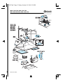
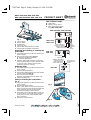
1.
Control panel.
2.
Grease filters.
3.
Lighting unit.
4.
Telescopic flue.
5.
Grease filter release-replace handle.
6.
Ladle holder (only DKR 3760-3790).
Removing and renewing or cleaning the
grease filter:
1.
Unplug the appliance or disconnect the mains
power supply.
2.
Remove the grease filters
(Fig. 1)
:
a
- push the handles backwards
b
- and then downwards.
3.
After the grease filter has been replaced or
cleaned (depending on model), refit the parts
in reverse order, making sure the entire
extraction surface is covered.
Replacing bulbs
1.
Unplug the appliance or disconnect the mains
power supply.
2.
Remove the grease filters.
3.
Remove the lighting unit from the clips that fix
it to the hood body
(Fig. 2)
.
4.
Remove the burnt-out bulb.
Replace using 40W max (E14) bulbs only.
5.
Refit the lighting unit.
Fitting or renewing the carbon filter -
Fig. 3:
1.
Unplug the appliance or disconnect the mains
power supply.
2.
Remove the grease filters.
3.
If the carbon filters are already mounted (two
filters covering the motor protection grille) and
need renewing, turn the central handle
anticlockwise until the filters release.
4.
If the filters are not already fitted, locate one
on each side to cover both motor protection
grilles, then turn the central handle of the
filters clockwise.
5.
Replace the grease filters.
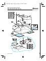
THE CONTROL PANEL
A.
Light switch.
B.
Speed selector switch.
C.
Valve open/closed switch
(only
MSK 3760-3790
).
DKE 3360-3390 / DKR 3760-3790
Fig. 1
Fig. 2
Fig. 3
small amount of
steam and fumes
medium amount of
steam and fumes
large
amount
of steam
and
fumes
DKEL 3760
DKEL 3790
MSK 3760
MSK 3790
valve closed
valve open
medium amount of
steam and fumes
small amount of
steam and fumes
large amount
of steam and
fumes
PRODUCT SHEET
DKE 3361
F NL E PGBD GRI
75187.fm5 Page 8 Friday, October 13, 2000 5:59 PM
-
 1
1
-
 2
2
-
 3
3
-
 4
4
-
 5
5
-
 6
6


Bauknecht DKE 3360 IN Program Chart
- Kategori
- Ocak davlumbazları
- Tip
- Program Chart
diğer dillerde
- español: Bauknecht DKE 3360 IN
- français: Bauknecht DKE 3360 IN
- italiano: Bauknecht DKE 3360 IN
- Deutsch: Bauknecht DKE 3360 IN
- português: Bauknecht DKE 3360 IN
- English: Bauknecht DKE 3360 IN
- Nederlands: Bauknecht DKE 3360 IN
İlgili makaleler
-
Bauknecht DKR 3760 SW Program Chart
-
-
-
-
-
-
-
Bauknecht DKEL 3860 IN Program Chart
-
Bauknecht DNHE 3760 IN Program Chart
-
