Dell PowerConnect 7024P Hızlı başlangıç Kılavuzu
- Kategori
- Ağ anahtarları
- Tip
- Hızlı başlangıç Kılavuzu

Dell PowerConnect
7000 Series Switch
Getting Started Guide
使用入门指南
入門指南
Guide de mise en route
Handbuch zum Einstieg
Panduan Pengaktifan
はじめに
시작 안내서
Guía de introducción
Başlangıç Kılavuzu
Guia de Primeiros Passos
Regulatory models: PC7024, PC7024P,
PC7024F, PC7048, PC7048P, and PC7048R


Dell PowerConnect
7000 Series Switch
Getting Started Guide
Regulatory Models: PC7024, PC7024P,
PC7024F, PC7048, PC7048P, PC7048R,
and PC7048R-RA

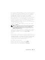
Notes, Cautions, and Warnings
NOTE: A NOTE indicates important information that helps you make better use
of your computer.
CAUTION: A CAUTION indicates potential damage to hardware or loss of data
if instructions are not followed.
WARNING: A WARNING indicates a potential for property damage, personal
injury, or death.
____________________
Information in this publication is subject to change without notice.
© 2011 Dell Inc. All rights reserved.
Reproduction of these materials in any manner whatsoever without the written permission of Dell Inc.
is strictly forbidden.
Trademarks used in this text: Dell™, the DELL logo, PowerConnect™, and OpenManage™ are
trademarks of Dell Inc. Microsoft
®
, Windows
®
, Windows Server
®
, MS-DOS
®
and Windows Vista
®
are either trademarks or registered trademarks of Microsoft Corporation in the United States and/or
other countries.
Other trademarks and trade names may be used in this publication to refer to either the entities claiming
the marks and names or their products. Dell Inc. disclaims any proprietary interest in trademarks and
trade names other than its own.
Regulatory Models: PC7024, PC7024P, PC7024F, PC7048, PC7048P, PC7048R, and PC7048R-RA
March 2011 P/N D3R71 Rev. A00

Contents 3
Contents
1 Introduction . . . . . . . . . . . . . . . . . . . . . . . . 5
PowerConnect 7000 Series Overview . . . . . . . . . . . 5
2 Hardware Overview. . . . . . . . . . . . . . . . . . 6
PowerConnect 7000 Series Front Panel . . . . . . . . . . 6
Switch Ports
. . . . . . . . . . . . . . . . . . . . . 9
Console Port
. . . . . . . . . . . . . . . . . . . . . 9
Out-of-Band Management Port
. . . . . . . . . . 10
USB Port
. . . . . . . . . . . . . . . . . . . . . . 10
Reset Button
. . . . . . . . . . . . . . . . . . . . 10
Port and System LEDs
. . . . . . . . . . . . . . . 10
Stack Master LED and Stack
Number Display
. . . . . . . . . . . . . . . . . . . 11
PowerConnect 7000 Series Back Panel
. . . . . . . . . 11
Expansion Slots for Plug-in Modules
. . . . . . . . 12
Power Supplies
. . . . . . . . . . . . . . . . . . . 12
Ventilation System
. . . . . . . . . . . . . . . . . 13
Locator LED
. . . . . . . . . . . . . . . . . . . . . 13

4 Contents
3Installation. . . . . . . . . . . . . . . . . . . . . . . 14
Site Preparation . . . . . . . . . . . . . . . . . . . . . 14
Unpacking the Switch
. . . . . . . . . . . . . . . . . . 14
Package Contents
. . . . . . . . . . . . . . . . . . 14
Unpacking Steps
. . . . . . . . . . . . . . . . . . 15
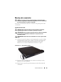
Mounting the Switch
. . . . . . . . . . . . . . . . . . . 15
Installing in a Rack
. . . . . . . . . . . . . . . . . 15
Installing as a Free-standing Switch
. . . . . . . . 17
Stacking Multiple Switches
. . . . . . . . . . . . . . . 17
Creating a Switch Stack
. . . . . . . . . . . . . . 17
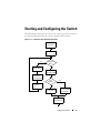
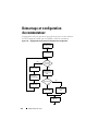
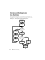
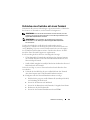
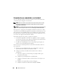
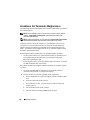
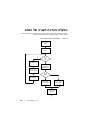
4 Starting and Configuring the Switch . . . 19
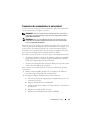
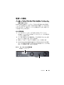
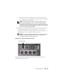
Connecting a Switch to a Terminal . . . . . . . . . . . 20
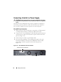
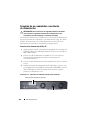
Connecting a Switch to a Power Supply
. . . . . . . . 22
AC and DC Power Connection
. . . . . . . . . . . 22
Booting the Switch
. . . . . . . . . . . . . . . . . . . . 23
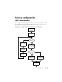
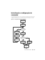
Performing the Initial Configuration
. . . . . . . . . . . 23
Enabling Remote Management
. . . . . . . . . . . 24
Initial Configuration Procedure
. . . . . . . . . . . 24
Example Session
. . . . . . . . . . . . . . . . . . 25
Next Steps
. . . . . . . . . . . . . . . . . . . . . 29
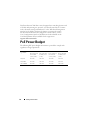
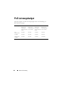
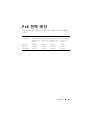
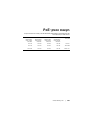
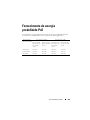
5 PoE Power Budget . . . . . . . . . . . . . . . . . 30

Getting Started Guide 5
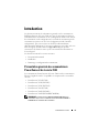
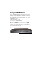
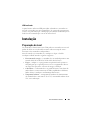
Introduction
This document provides basic information about the Dell PowerConnect
7000 Series switches, including how to install a switch and perform the initial
configuration. For information about how to configure and monitor switch
features, see the User’s Configuration Guide, which is available on your User
Documentation CD, or check the Dell Support website at support.dell.com
for the latest updates on documentation and firmware.
This document contains the following sections:
• Hardware Overview
• Installation
• Starting and Configuring the Switch
PowerConnect 7000 Series Overview
The PowerConnect 7000 Series switches are stackable Layer 3 Gigabit
Ethernet switches and include the following six models:
• PowerConnect 7024 (PC7024)
• PowerConnect 7024P (PC7024P)
• PowerConnect 7024F (PC7024F)
• PowerConnect 7048 (PC7048)
• PowerConnect 7048P (PC7048P)
• PowerConnect 7048R (PC7048R/PC7048R-RA)
NOTE: The PowerConnect 7048R (PC7048R/PC7048R-RA) is a top-of-rack switch.
The difference between the PC7048R and PC7048R-RA models is the air-flow
direction.

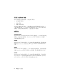
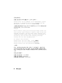
6 Getting Started Guide
Hardware Overview
This section contains information about device characteristics and modular
hardware configurations for the PowerConnect 7000 Series switches.
All models are 1U, rack mountable switches with the following physical
dimensions:
• 440 x 460 x 44 mm (W x D x H).
• 17.3 x 18.1 x 1.7 inch (W x D x H).
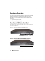
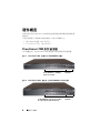
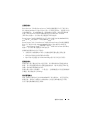
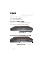
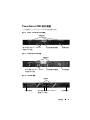
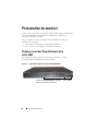
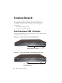
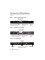
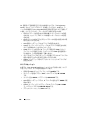
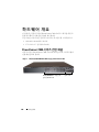
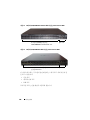
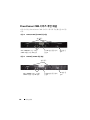
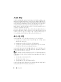
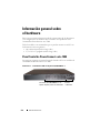
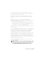
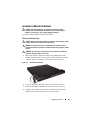
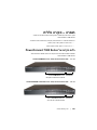
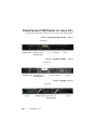
PowerConnect 7000 Series Front Panel
The following images show the front panels of the six switch models in the
PowerConnect 7000 Series.
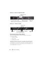
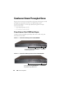
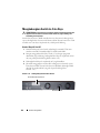
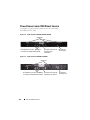
Figure 1-1. PowerConnect 7024 with 24 10/100/1000BASE-T Ports
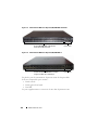
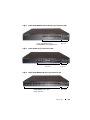
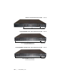
Figure 1-2. PowerConnect 7024P with 24 10/100/1000BASE-T PoE Plus Ports
Combo Ports10/100/1000BASE-T Auto-sensing
Full Duplex RJ-45 Ports
Combo Ports10/100/1000BASE-T RJ-45 PoE Plus Ports
Providing up to 30W per Port

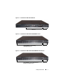
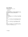
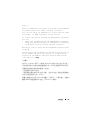
Getting Started Guide 7
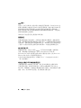
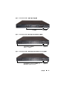
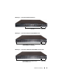
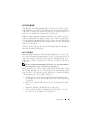
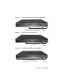
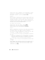
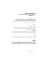
Figure 1-3. PowerConnect 7024F with 24 SFP Ports
Figure 1-4. PowerConnect 7048 with 48 10/100/1000BASE-T Ports
Figure 1-5. PowerConnect 7048P with 48 10/100/1000BASE-T PoE Plus Ports
SFP Ports Combo Ports
Combo Ports10/100/1000BASE-T Auto-sensing
Full Duplex RJ-45 Ports
Combo Ports10/100/1000BASE-T RJ-45 PoE Plus Ports
Providing up to 30W per Port

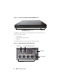
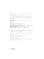
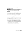
8 Getting Started Guide
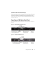
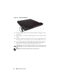
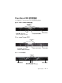
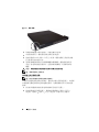
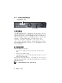
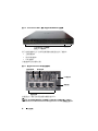
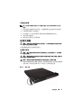
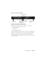
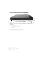
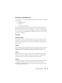
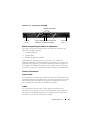
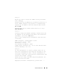
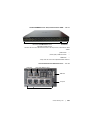
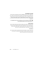
Figure 1-6. PowerConnect 7048R with 48 10/100/1000BASE-T Ports
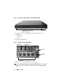
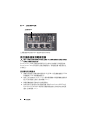
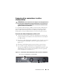
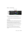
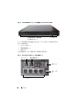
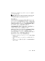
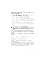
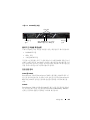
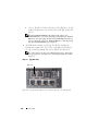
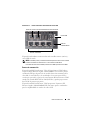
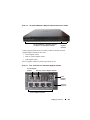
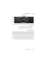
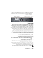
In addition to the switch ports, the front panel of each model in the series
includes the following ports:
• Console port
• Out-of-band management port
• USB port
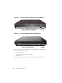
The additional ports are on the right side of the front panel.
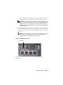
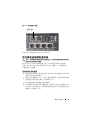
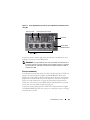
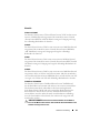
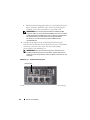
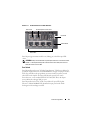
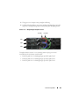
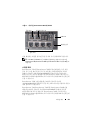
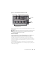
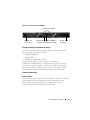
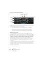
Figure 1-7. Additional PowerConnect 7000 Series Ports
Combo Ports
10/100/1000BASE-T Auto-sensing
Full Duplex RJ-45 Ports
Combo Ports
Reset Button
USB Port
Console Port Out-of-Band Management Port

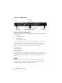
Getting Started Guide 9
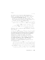
The front panel also contains a reset button (pinhole) and several status
LEDs.
NOTE: The port LEDs and system LEDs on the front panel are not the same for all
models. Figure 1-7 shows the LEDs on the PowerConnect 7024, PowerConnect
7024F, and PowerConnect 7048 switches.
Switch Ports
The PowerConnect 7024 and PowerConnect 7024P front panel provides
24 Gigabit Ethernet (10/100/1000BASE-T) RJ-45 ports with four SFP combo
ports that have an auto-sensing mode for speed, flow control, and duplex
mode. SFP transceivers are sold separately. The PowerConnect 7024P switch
ports are IEEE 802.3at-2009-compliant (PoE Plus) and can provided up to
30W of power per port.
The PowerConnect 7024F front panel provides 20 Gigabit Ethernet
(10/100/1000BASE-FX) SFP ports plus 4 combo ports for copper or SFP
media support.
The PowerConnect 7048, PowerConnect 7048P, and PowerConnect 7048R
front panel provides 48 Gigabit Ethernet (10/100/1000BASE-T) RJ-45 ports
with four SFP combo ports. The PowerConnect 7048P switch ports are
IEEE 802.3at-2009-compliant (PoE Plus) and can provided up to 30W of
power per port.
The front-panel switch ports have the following characteristics:
• The switch automatically detects the difference between crossed and
straight-through cables on RJ-45 ports.
• SFP ports support both SX and LX modules.
• RJ-45 ports support half- and full-duplex mode 10/100/1000 Mbps.
Console Port
The console port is for management through a serial interface. This port
provides a direct connection to the switch and allows you to access the CLI
from a console terminal connected to the port through the provided serial
cable (RJ-45 to female DB-9 connectors).
The console port supports asynchronous data of eight data bits, one stop bit, no
parity bit, and no flow control. The default baud rate is 9600 bps.

10 Getting Started Guide
Out-of-Band Management Port
The Out-of-Band (OOB) management port is a 10/100/1000BASE-T
Ethernet port dedicated to remote switch management. Traffic on this port is
segregated from operational network traffic on the switch ports and cannot be
switched or routed to the operational network.
USB Port
The Type-A, female USB port supports a USB 2.0-compliant flash memory
drive. The PowerConnect switch can read or write to a flash drive formatted
as FAT-32. You can use a USB flash drive to copy switch configuration files
and images between the USB flash drive and the switch. You can also use the
USB flash drive to move and copy configuration files and images from one
switch to other switches in the network.
The USB port does not support any other type of USB device.
Reset Button
The reset button is accessed through the pinhole and allows you to perform a
hard reset on the switch. To use the reset button, insert an unbent paper clip
or similar tool into the pinhole. When the switch completes the boot process
after the reset, it resumes operation with the most recently saved
configuration. Any changes made to the running configuration that were not
saved to the startup configuration prior to the reset are lost.
Port and System LEDs
The front panel contains light emitting diodes (LEDs) that indicate the
status of port links, power supplies, fans, stacking, and the overall system.
Additionally, the PowerConnect 7024P and PowerConnect 7048P switches
contain LEDs that provide information about Power over Ethernet Plus
(PoE+) status and activity on the ports.
For information about the status that the LEDs indicate, see the User’s
Configuration Guide.

Getting Started Guide 11
Stack Master LED and Stack Number Display
When a switch within a stack is the master unit, the stack master LED, which
is labeled M, is solid green. If the M LED is off, the stack member is not the
master unit. The Stack No. panel displays the unit number for the stack
member. If a switch is not part of a stack, the M LED is illuminated and the
stack unit number is 1.
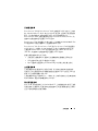
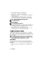
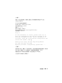
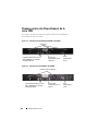
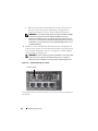
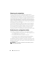
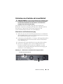
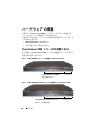
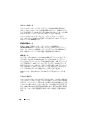
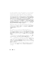
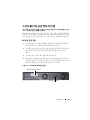
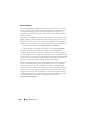
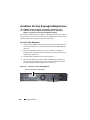
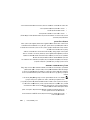
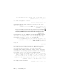
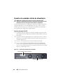
PowerConnect 7000 Series Back Panel
The following images show the back panel of the PowerConnect 7000 Series
switches.
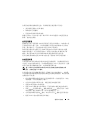
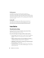
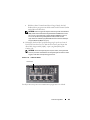
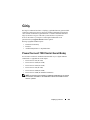
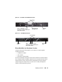
Figure 1-8. PC7024, PC7024F, and PC7048 Back Panel
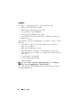
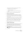
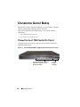
Figure 1-9. PC7024P and PC7048P Back Panel
Dual 10G Slots for SFP+, 10GBASE-T,
or Stacking/10GbE Modules
AC Power
Receptacle
Redundant DC Power
Supply Receptacle
Fan Vents
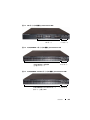
AC Power
Receptacle
External DC Power
Supply Receptacle
Fan Vents
Dual 10G Slots for SFP+, 10GBASE-T,
or Stacking/10 GbE Modules

12 Getting Started Guide
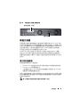
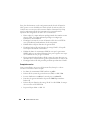
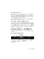
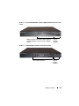
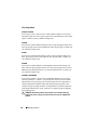
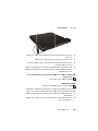
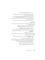
Figure 1-10. PC7048R Back Panel
Expansion Slots for Plug-in Modules
Two expansion slots are located on the back of the switch and can support the
following modules:
• 10GBASE-T module
• SFP+ module
• Stacking/10 GbE module
Each plug-in module has two ports. The Stacking/10GbE modules can be
configured to operate as either 16-Gigabit stacking ports or 10-Gigabit
Ethernet switch ports. The plug-in modules include hot-swap support, so you
do not need to reboot the switch after you install a new module.
Power Supplies
PC7024 and PC7024F
PowerConnect 7024 and PowerConnect 7024F switches have an internal
180-watt power supply. The additional external power supply (PowerConnect
RPS720) provides 180 watts of power and gives full redundancy for the
switch.
PC7024P
PowerConnect 7024P switches have an internal 1000-watt power supply.
The additional external power supply (PowerConnect MPS1000) provides
1000 Watts and gives full redundancy for the switch.
AC Power
Receptacle
Fan Trays
AC Power
Receptacle
Dual 10G Slots for SFP+, 10GBASE-T,
or Stacking/10GbE Modules

Getting Started Guide 13
PC7048
PowerConnect 7048 switches have an internal 180-watt power supply.
The additional external power supply (PowerConnect RPS720) provides
180 watts and gives full redundancy for the switch.
PC7048P
PowerConnect 7048P switches have an internal 1000-watt power supply
which can support up to 24 ports of PoE. The additional external power
supply (PowerConnect MPS1000) allows all 48 ports of PoE, or 24 ports of
PoE and full redundancy for the switch.
PC7048R and PC7048R-RA
PowerConnect 7048R and PowerConnect 7048R-RA switches are designed as
top-of-rack switches and include two internal, replaceable, AC power supplies
for redundant or load-sharing operation. Each power supply can provide
300 watts and includes hot-swap support. This means you do not need to
power-down the switch to remove or replace one power supply while the other
power supply is operating normally. However, it is necessary to remove power
from the power supply that is being removed or replaced.
CAUTION: Remove the power cable from the modules prior to removing the
module itself. Power must not be connected prior to insertion in the chassis.
Ventilation System
Three fans cool the PowerConnect 7024, PowerConnect 7024F, and
PowerConnect 7048. The PowerConnect 7024P and PowerConnect 7048P
each have two fans, with a third fan in the internal power supply.
The PowerConnect 7048R has two hot-swappable fan trays with one fan each.
Locator LED
The back panel includes an LED to help identify the switch within a rack or
room full of switches. From your remote management system, you can set the
LED to blink to help you or a local technician identify the physical location of
the switch.

14 Getting Started Guide
Installation
Site Preparation
PowerConnect 7000 Series switches can be mounted in a standard 48.26-cm
(19-inch) rack or left freestanding (placed on a flat surface) and function as
stand-alone switches.
Before installing the switch or switches, make sure that the chosen
installation location meets the following site requirements:
•
Power
— The switch is installed near an easily accessible 100–240 VAC,
50–60 Hz outlet.
•
Clearance
— There is adequate front and rear clearance for operator
access. Allow clearance for cabling, power connections, and ventilation.
•
Cabling
— The cabling is routed to avoid sources of electrical noise such
as radio transmitters, broadcast amplifiers, power lines, and fluorescent
lighting fixtures.
•
Ambient Temperature
— The ambient switch operating temperature
range is 0 to 45ºC (32 to 113ºF) at a relative humidity of up to 95 percent,
non-condensing.
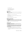
Unpacking the Switch
Package Contents
When unpacking each switch, make sure that the following items are
included:
• One PowerConnect switch
• One AC power cable (two AC power cables for the PowerConnect 7048R)
• One RJ-45 to DB-9 female cable
• One rack-mount kit for rack installation (two mounting brackets, bolts,
and cage nuts)
• One set of self-adhesive rubber pads for the free-standing switch (four pads
are included)
•
User Documentation
CD

Getting Started Guide 15
• Getting Started Guide
• Safety and Regulatory Information
• Warranty and Support Information
• Software License Agreement
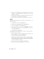
Unpacking Steps
NOTE: Before unpacking the switch, inspect the container and immediately report
any evidence of damage.
1
Place the container on a clean, flat surface and cut all straps securing the
container.
2
Open the container or remove the container top.
3
Carefully remove the switch from the container and place it on a secure
and clean surface.
4
Remove all packing material.
5
Inspect the product and accessories for damage.
Mounting the Switch
WARNING: Read the safety information in the Safety and Regulatory Information
as well as the safety information for other switches that connect to or support the
switch.
The AC power connector is on the back panel of the switch.
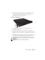
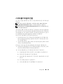
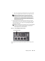
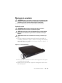
Installing in a Rack
WARNING: Do not use rack mounting kits to suspend the switch from under a
table or desk, or attach it to a wall.
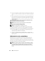
CAUTION: Disconnect all cables from the switch before continuing. Remove all
self-adhesive pads from the underside of the switch, if they have been attached.
CAUTION: When mounting multiple switches into a rack, mount the switches
from the bottom up.
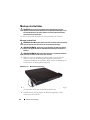
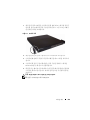
1
Place the supplied rack-mounting bracket on one side of the switch,
ensuring that the mounting holes on the switch line up to the mounting
holes in the rack-mounting bracket. Figure 1-11 illustrates where to mount
the brackets.

16 Getting Started Guide
Figure 1-11. Attaching the Brackets
2
Insert the supplied bolts into the rack-mounting holes and tighten with a
screwdriver.
3
Repeat the process for the rack-mounting bracket on the other side of the
switch.
4
Insert the switch into the 48.26 cm (19 inch) rack, ensuring that the rack-
mounting holes on the switch line up to the mounting holes in the rack.
5
Secure the switch to the rack with either the rack bolts or cage nuts and
cage-nut bolts with washers (depending on the kind of rack you have).
Fasten the bolts on bottom before fastening the bolts on top.
CAUTION: Make sure that the supplied rack bolts fit the pre-threaded holes in the
rack.
NOTE: Make sure that the ventilation holes are not obstructed.

Getting Started Guide 17
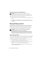
Installing as a Free-standing Switch
NOTE: We strongly recommend mounting the switch in a rack.
Install the switch on a flat surface if you are not installing it in a rack.
The surface must be able to support the weight of the switch and the switch
cables. The switch is supplied with four self-adhesive rubber pads.
1
Attach the self-adhesive rubber pads on each location marked on the
bottom of the switch.
2
Set the switch on a flat surface, and make sure that it has proper
ventilation by leaving 5 cm (2 inches) on each side and 13 cm (5 inches) at
the back.
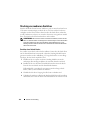
Stacking Multiple Switches
You can stack PowerConnect PowerConnect 7000 Series switches up to
12 switches high, supporting up to 576 front panel ports. When multiple
switches are connected together through the stack ports, they operate as a
single unit with a larger port count. The stack operates and is managed as a
single entity.
NOTE: If you are installing a stack of switches, you need to assemble and cable the
stack before powering up and configuring it. When a stack is powered up for the
first time, the switches elect a Master Switch, which may occupy any location in
the stack. The Master LED on the front panel is illuminated on the master unit.
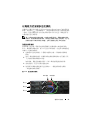
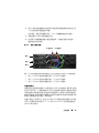
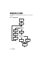
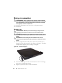
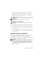
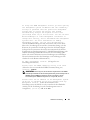
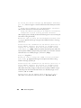
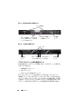
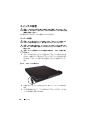
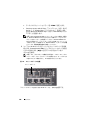
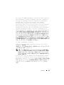
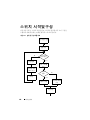
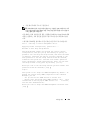
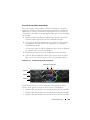
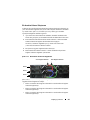
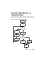
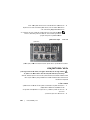
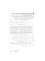
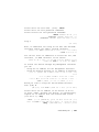
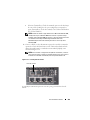
Creating a Switch Stack
Create a stack by connecting adjacent units using the stacking ports on the
back panel of the switch. Stacking modules are sold separately. Figure 1-12
shows the switches connected in a ring topology, which is the recommended
topology for a stack.
1
Install a separately purchased stacking module in one of the rear expansion
slots for each of the switches in the stack.
2
Connect one of the short stacking cables into either of the stacking ports
of the top switch and the switch directly below it.
If necessary, use a separately purchased, long (3 meter) stacking cable to
connect the switches.

18 Getting Started Guide
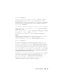
3
Repeat this process until all of the devices are connected.
4
Use the remaining stacking cable to connect the remaining free ports,
one each on the top and bottom switches.
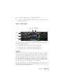
Figure 1-12. Connecting a Stack of Switches
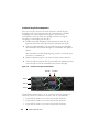
The stack in Figure 1-12 is connected in a ring topology and has the following
physical connections between the switches:
• The XG1 port on Unit 1 is connected to the XG2 port on Unit 2.
• The XG1 port on Unit 2 is connected to the XG4 port on Unit 3.
• The XG3 port on Unit 3 is connected to the XG2 port on Unit 1.
Stacking Standby
The stacking feature supports a Standby or backup unit that assumes the
Master unit role if the Master unit in the stack fails. As soon as a Master
failure is detected in the stack, the Standby unit initializes the control plane
and enables all other stack units with the current configuration. The Standby
unit maintains a synchronized copy of the running configuration for the
stack. During switchover, all the ports are brought down and brought up to
avoid possible loops and to get new master software applications to a
consistent state.
The Standby unit is pre-configured in the stack; however, you can use the CLI
to select a different stack member as Standby. See the User’s Configuration
Guide or the CLI Reference Guide for more information.
Unit 1
Unit 2
Unit 3
XG1 Port XG2 Port
Sayfa yükleniyor...
Sayfa yükleniyor...
Sayfa yükleniyor...
Sayfa yükleniyor...
Sayfa yükleniyor...
Sayfa yükleniyor...
Sayfa yükleniyor...
Sayfa yükleniyor...
Sayfa yükleniyor...
Sayfa yükleniyor...
Sayfa yükleniyor...
Sayfa yükleniyor...
Sayfa yükleniyor...
Sayfa yükleniyor...
Sayfa yükleniyor...
Sayfa yükleniyor...
Sayfa yükleniyor...
Sayfa yükleniyor...
Sayfa yükleniyor...
Sayfa yükleniyor...
Sayfa yükleniyor...
Sayfa yükleniyor...
Sayfa yükleniyor...
Sayfa yükleniyor...
Sayfa yükleniyor...
Sayfa yükleniyor...
Sayfa yükleniyor...
Sayfa yükleniyor...
Sayfa yükleniyor...
Sayfa yükleniyor...
Sayfa yükleniyor...
Sayfa yükleniyor...
Sayfa yükleniyor...
Sayfa yükleniyor...
Sayfa yükleniyor...
Sayfa yükleniyor...
Sayfa yükleniyor...
Sayfa yükleniyor...
Sayfa yükleniyor...
Sayfa yükleniyor...
Sayfa yükleniyor...
Sayfa yükleniyor...
Sayfa yükleniyor...
Sayfa yükleniyor...
Sayfa yükleniyor...
Sayfa yükleniyor...
Sayfa yükleniyor...
Sayfa yükleniyor...
Sayfa yükleniyor...
Sayfa yükleniyor...
Sayfa yükleniyor...
Sayfa yükleniyor...
Sayfa yükleniyor...
Sayfa yükleniyor...
Sayfa yükleniyor...
Sayfa yükleniyor...
Sayfa yükleniyor...
Sayfa yükleniyor...
Sayfa yükleniyor...
Sayfa yükleniyor...
Sayfa yükleniyor...
Sayfa yükleniyor...
Sayfa yükleniyor...
Sayfa yükleniyor...
Sayfa yükleniyor...
Sayfa yükleniyor...
Sayfa yükleniyor...
Sayfa yükleniyor...
Sayfa yükleniyor...
Sayfa yükleniyor...
Sayfa yükleniyor...
Sayfa yükleniyor...
Sayfa yükleniyor...
Sayfa yükleniyor...
Sayfa yükleniyor...
Sayfa yükleniyor...
Sayfa yükleniyor...
Sayfa yükleniyor...
Sayfa yükleniyor...
Sayfa yükleniyor...
Sayfa yükleniyor...
Sayfa yükleniyor...
Sayfa yükleniyor...
Sayfa yükleniyor...
Sayfa yükleniyor...
Sayfa yükleniyor...
Sayfa yükleniyor...
Sayfa yükleniyor...
Sayfa yükleniyor...
Sayfa yükleniyor...
Sayfa yükleniyor...
Sayfa yükleniyor...
Sayfa yükleniyor...
Sayfa yükleniyor...
Sayfa yükleniyor...
Sayfa yükleniyor...
Sayfa yükleniyor...
Sayfa yükleniyor...
Sayfa yükleniyor...
Sayfa yükleniyor...
Sayfa yükleniyor...
Sayfa yükleniyor...
Sayfa yükleniyor...
Sayfa yükleniyor...
Sayfa yükleniyor...
Sayfa yükleniyor...
Sayfa yükleniyor...
Sayfa yükleniyor...
Sayfa yükleniyor...
Sayfa yükleniyor...
Sayfa yükleniyor...
Sayfa yükleniyor...
Sayfa yükleniyor...
Sayfa yükleniyor...
Sayfa yükleniyor...
Sayfa yükleniyor...
Sayfa yükleniyor...
Sayfa yükleniyor...
Sayfa yükleniyor...
Sayfa yükleniyor...
Sayfa yükleniyor...
Sayfa yükleniyor...
Sayfa yükleniyor...
Sayfa yükleniyor...
Sayfa yükleniyor...
Sayfa yükleniyor...
Sayfa yükleniyor...
Sayfa yükleniyor...
Sayfa yükleniyor...
Sayfa yükleniyor...
Sayfa yükleniyor...
Sayfa yükleniyor...
Sayfa yükleniyor...
Sayfa yükleniyor...
Sayfa yükleniyor...
Sayfa yükleniyor...
Sayfa yükleniyor...
Sayfa yükleniyor...
Sayfa yükleniyor...
Sayfa yükleniyor...
Sayfa yükleniyor...
Sayfa yükleniyor...
Sayfa yükleniyor...
Sayfa yükleniyor...
Sayfa yükleniyor...
Sayfa yükleniyor...
Sayfa yükleniyor...
Sayfa yükleniyor...
Sayfa yükleniyor...
Sayfa yükleniyor...
Sayfa yükleniyor...
Sayfa yükleniyor...
Sayfa yükleniyor...
Sayfa yükleniyor...
Sayfa yükleniyor...
Sayfa yükleniyor...
Sayfa yükleniyor...
Sayfa yükleniyor...
Sayfa yükleniyor...
Sayfa yükleniyor...
Sayfa yükleniyor...
Sayfa yükleniyor...
Sayfa yükleniyor...
Sayfa yükleniyor...
Sayfa yükleniyor...
Sayfa yükleniyor...
Sayfa yükleniyor...
Sayfa yükleniyor...
Sayfa yükleniyor...
Sayfa yükleniyor...
Sayfa yükleniyor...
Sayfa yükleniyor...
Sayfa yükleniyor...
Sayfa yükleniyor...
Sayfa yükleniyor...
Sayfa yükleniyor...
Sayfa yükleniyor...
Sayfa yükleniyor...
Sayfa yükleniyor...
Sayfa yükleniyor...
Sayfa yükleniyor...
Sayfa yükleniyor...
Sayfa yükleniyor...
Sayfa yükleniyor...
Sayfa yükleniyor...
Sayfa yükleniyor...
Sayfa yükleniyor...
Sayfa yükleniyor...
Sayfa yükleniyor...
Sayfa yükleniyor...
Sayfa yükleniyor...
Sayfa yükleniyor...
Sayfa yükleniyor...
Sayfa yükleniyor...
Sayfa yükleniyor...
Sayfa yükleniyor...
Sayfa yükleniyor...
Sayfa yükleniyor...
Sayfa yükleniyor...
Sayfa yükleniyor...
Sayfa yükleniyor...
Sayfa yükleniyor...
Sayfa yükleniyor...
Sayfa yükleniyor...
Sayfa yükleniyor...
Sayfa yükleniyor...
Sayfa yükleniyor...
Sayfa yükleniyor...
Sayfa yükleniyor...
Sayfa yükleniyor...
Sayfa yükleniyor...
Sayfa yükleniyor...
Sayfa yükleniyor...
Sayfa yükleniyor...
Sayfa yükleniyor...
Sayfa yükleniyor...
Sayfa yükleniyor...
Sayfa yükleniyor...
Sayfa yükleniyor...
Sayfa yükleniyor...
Sayfa yükleniyor...
Sayfa yükleniyor...
Sayfa yükleniyor...
Sayfa yükleniyor...
Sayfa yükleniyor...
Sayfa yükleniyor...
Sayfa yükleniyor...
Sayfa yükleniyor...
Sayfa yükleniyor...
Sayfa yükleniyor...
Sayfa yükleniyor...
Sayfa yükleniyor...
Sayfa yükleniyor...
Sayfa yükleniyor...
Sayfa yükleniyor...
Sayfa yükleniyor...
Sayfa yükleniyor...
Sayfa yükleniyor...
Sayfa yükleniyor...
Sayfa yükleniyor...
Sayfa yükleniyor...
Sayfa yükleniyor...
Sayfa yükleniyor...
Sayfa yükleniyor...
Sayfa yükleniyor...
Sayfa yükleniyor...
Sayfa yükleniyor...
Sayfa yükleniyor...
Sayfa yükleniyor...
Sayfa yükleniyor...
Sayfa yükleniyor...
Sayfa yükleniyor...
Sayfa yükleniyor...
Sayfa yükleniyor...
Sayfa yükleniyor...
Sayfa yükleniyor...
Sayfa yükleniyor...
Sayfa yükleniyor...
Sayfa yükleniyor...
Sayfa yükleniyor...
Sayfa yükleniyor...
Sayfa yükleniyor...
Sayfa yükleniyor...
Sayfa yükleniyor...
Sayfa yükleniyor...
Sayfa yükleniyor...
Sayfa yükleniyor...
Sayfa yükleniyor...
Sayfa yükleniyor...
Sayfa yükleniyor...
Sayfa yükleniyor...
Sayfa yükleniyor...
Sayfa yükleniyor...
Sayfa yükleniyor...
Sayfa yükleniyor...
Sayfa yükleniyor...
Sayfa yükleniyor...
Sayfa yükleniyor...
Sayfa yükleniyor...
Sayfa yükleniyor...
Sayfa yükleniyor...
Sayfa yükleniyor...
Sayfa yükleniyor...
Sayfa yükleniyor...
Sayfa yükleniyor...
Sayfa yükleniyor...
Sayfa yükleniyor...
Sayfa yükleniyor...
Sayfa yükleniyor...
Sayfa yükleniyor...
Sayfa yükleniyor...
Sayfa yükleniyor...
Sayfa yükleniyor...
Sayfa yükleniyor...
Sayfa yükleniyor...
Sayfa yükleniyor...
Sayfa yükleniyor...
Sayfa yükleniyor...
Sayfa yükleniyor...
Sayfa yükleniyor...
Sayfa yükleniyor...
Sayfa yükleniyor...
Sayfa yükleniyor...
Sayfa yükleniyor...
Sayfa yükleniyor...
Sayfa yükleniyor...
Sayfa yükleniyor...
Sayfa yükleniyor...
Sayfa yükleniyor...
Sayfa yükleniyor...
Sayfa yükleniyor...
Sayfa yükleniyor...
Sayfa yükleniyor...
Sayfa yükleniyor...
Sayfa yükleniyor...
Sayfa yükleniyor...
Sayfa yükleniyor...
Sayfa yükleniyor...
Sayfa yükleniyor...
Sayfa yükleniyor...
Sayfa yükleniyor...
Sayfa yükleniyor...
Sayfa yükleniyor...
Sayfa yükleniyor...
Sayfa yükleniyor...
Sayfa yükleniyor...
Sayfa yükleniyor...
Sayfa yükleniyor...
Sayfa yükleniyor...
Sayfa yükleniyor...
Sayfa yükleniyor...
Sayfa yükleniyor...
Sayfa yükleniyor...
Sayfa yükleniyor...
Sayfa yükleniyor...
Sayfa yükleniyor...
Sayfa yükleniyor...
Sayfa yükleniyor...
Sayfa yükleniyor...
Sayfa yükleniyor...
Sayfa yükleniyor...
Sayfa yükleniyor...
Sayfa yükleniyor...
Sayfa yükleniyor...
Sayfa yükleniyor...
Sayfa yükleniyor...
Sayfa yükleniyor...
Sayfa yükleniyor...
Sayfa yükleniyor...
Sayfa yükleniyor...
Sayfa yükleniyor...
Sayfa yükleniyor...
Sayfa yükleniyor...
Sayfa yükleniyor...
Sayfa yükleniyor...
Sayfa yükleniyor...
Sayfa yükleniyor...
Sayfa yükleniyor...
Sayfa yükleniyor...
Sayfa yükleniyor...
Sayfa yükleniyor...
Sayfa yükleniyor...
Sayfa yükleniyor...
Sayfa yükleniyor...
Sayfa yükleniyor...
Sayfa yükleniyor...
Sayfa yükleniyor...
Sayfa yükleniyor...
Sayfa yükleniyor...
Sayfa yükleniyor...
Sayfa yükleniyor...
Sayfa yükleniyor...
Sayfa yükleniyor...
Sayfa yükleniyor...
Sayfa yükleniyor...
Sayfa yükleniyor...
Sayfa yükleniyor...
Sayfa yükleniyor...
Sayfa yükleniyor...
Sayfa yükleniyor...
Sayfa yükleniyor...
Sayfa yükleniyor...
-
 1
1
-
 2
2
-
 3
3
-
 4
4
-
 5
5
-
 6
6
-
 7
7
-
 8
8
-
 9
9
-
 10
10
-
 11
11
-
 12
12
-
 13
13
-
 14
14
-
 15
15
-
 16
16
-
 17
17
-
 18
18
-
 19
19
-
 20
20
-
 21
21
-
 22
22
-
 23
23
-
 24
24
-
 25
25
-
 26
26
-
 27
27
-
 28
28
-
 29
29
-
 30
30
-
 31
31
-
 32
32
-
 33
33
-
 34
34
-
 35
35
-
 36
36
-
 37
37
-
 38
38
-
 39
39
-
 40
40
-
 41
41
-
 42
42
-
 43
43
-
 44
44
-
 45
45
-
 46
46
-
 47
47
-
 48
48
-
 49
49
-
 50
50
-
 51
51
-
 52
52
-
 53
53
-
 54
54
-
 55
55
-
 56
56
-
 57
57
-
 58
58
-
 59
59
-
 60
60
-
 61
61
-
 62
62
-
 63
63
-
 64
64
-
 65
65
-
 66
66
-
 67
67
-
 68
68
-
 69
69
-
 70
70
-
 71
71
-
 72
72
-
 73
73
-
 74
74
-
 75
75
-
 76
76
-
 77
77
-
 78
78
-
 79
79
-
 80
80
-
 81
81
-
 82
82
-
 83
83
-
 84
84
-
 85
85
-
 86
86
-
 87
87
-
 88
88
-
 89
89
-
 90
90
-
 91
91
-
 92
92
-
 93
93
-
 94
94
-
 95
95
-
 96
96
-
 97
97
-
 98
98
-
 99
99
-
 100
100
-
 101
101
-
 102
102
-
 103
103
-
 104
104
-
 105
105
-
 106
106
-
 107
107
-
 108
108
-
 109
109
-
 110
110
-
 111
111
-
 112
112
-
 113
113
-
 114
114
-
 115
115
-
 116
116
-
 117
117
-
 118
118
-
 119
119
-
 120
120
-
 121
121
-
 122
122
-
 123
123
-
 124
124
-
 125
125
-
 126
126
-
 127
127
-
 128
128
-
 129
129
-
 130
130
-
 131
131
-
 132
132
-
 133
133
-
 134
134
-
 135
135
-
 136
136
-
 137
137
-
 138
138
-
 139
139
-
 140
140
-
 141
141
-
 142
142
-
 143
143
-
 144
144
-
 145
145
-
 146
146
-
 147
147
-
 148
148
-
 149
149
-
 150
150
-
 151
151
-
 152
152
-
 153
153
-
 154
154
-
 155
155
-
 156
156
-
 157
157
-
 158
158
-
 159
159
-
 160
160
-
 161
161
-
 162
162
-
 163
163
-
 164
164
-
 165
165
-
 166
166
-
 167
167
-
 168
168
-
 169
169
-
 170
170
-
 171
171
-
 172
172
-
 173
173
-
 174
174
-
 175
175
-
 176
176
-
 177
177
-
 178
178
-
 179
179
-
 180
180
-
 181
181
-
 182
182
-
 183
183
-
 184
184
-
 185
185
-
 186
186
-
 187
187
-
 188
188
-
 189
189
-
 190
190
-
 191
191
-
 192
192
-
 193
193
-
 194
194
-
 195
195
-
 196
196
-
 197
197
-
 198
198
-
 199
199
-
 200
200
-
 201
201
-
 202
202
-
 203
203
-
 204
204
-
 205
205
-
 206
206
-
 207
207
-
 208
208
-
 209
209
-
 210
210
-
 211
211
-
 212
212
-
 213
213
-
 214
214
-
 215
215
-
 216
216
-
 217
217
-
 218
218
-
 219
219
-
 220
220
-
 221
221
-
 222
222
-
 223
223
-
 224
224
-
 225
225
-
 226
226
-
 227
227
-
 228
228
-
 229
229
-
 230
230
-
 231
231
-
 232
232
-
 233
233
-
 234
234
-
 235
235
-
 236
236
-
 237
237
-
 238
238
-
 239
239
-
 240
240
-
 241
241
-
 242
242
-
 243
243
-
 244
244
-
 245
245
-
 246
246
-
 247
247
-
 248
248
-
 249
249
-
 250
250
-
 251
251
-
 252
252
-
 253
253
-
 254
254
-
 255
255
-
 256
256
-
 257
257
-
 258
258
-
 259
259
-
 260
260
-
 261
261
-
 262
262
-
 263
263
-
 264
264
-
 265
265
-
 266
266
-
 267
267
-
 268
268
-
 269
269
-
 270
270
-
 271
271
-
 272
272
-
 273
273
-
 274
274
-
 275
275
-
 276
276
-
 277
277
-
 278
278
-
 279
279
-
 280
280
-
 281
281
-
 282
282
-
 283
283
-
 284
284
-
 285
285
-
 286
286
-
 287
287
-
 288
288
-
 289
289
-
 290
290
-
 291
291
-
 292
292
-
 293
293
-
 294
294
-
 295
295
-
 296
296
-
 297
297
-
 298
298
-
 299
299
-
 300
300
-
 301
301
-
 302
302
-
 303
303
-
 304
304
-
 305
305
-
 306
306
-
 307
307
-
 308
308
-
 309
309
-
 310
310
-
 311
311
-
 312
312
-
 313
313
-
 314
314
-
 315
315
-
 316
316
-
 317
317
-
 318
318
-
 319
319
-
 320
320
-
 321
321
-
 322
322
-
 323
323
-
 324
324
-
 325
325
-
 326
326
-
 327
327
-
 328
328
-
 329
329
-
 330
330
-
 331
331
-
 332
332
-
 333
333
-
 334
334
-
 335
335
-
 336
336
-
 337
337
-
 338
338
-
 339
339
-
 340
340
-
 341
341
-
 342
342
-
 343
343
-
 344
344
-
 345
345
-
 346
346
-
 347
347
-
 348
348
-
 349
349
-
 350
350
-
 351
351
-
 352
352
-
 353
353
-
 354
354
-
 355
355
-
 356
356
-
 357
357
-
 358
358
-
 359
359
-
 360
360
-
 361
361
-
 362
362
-
 363
363
-
 364
364
-
 365
365
-
 366
366
-
 367
367
-
 368
368
-
 369
369
-
 370
370
-
 371
371
-
 372
372
-
 373
373
-
 374
374
-
 375
375
-
 376
376
-
 377
377
-
 378
378
-
 379
379
-
 380
380
-
 381
381
-
 382
382
-
 383
383
-
 384
384
-
 385
385
-
 386
386
-
 387
387
-
 388
388
-
 389
389
-
 390
390
-
 391
391
-
 392
392
-
 393
393
-
 394
394
-
 395
395
-
 396
396
-
 397
397
-
 398
398
-
 399
399
-
 400
400
-
 401
401
-
 402
402


Dell PowerConnect 7024P Hızlı başlangıç Kılavuzu
- Kategori
- Ağ anahtarları
- Tip
- Hızlı başlangıç Kılavuzu