
English Français Deutsch Svenska Italiano Español Nederlands Русский
G
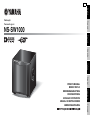
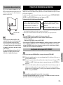
Subwoofer
Caisson de grave
NS-SW1000
OWNER’S MANUAL
MODE D’EMPLOI
BEDIENUNGSANLEITUNG
BRUKSANVISNING
MANUALE DI ISTRUZIONI
MANUAL DE INSTRUCCIONES
GEBRUIKSAANWIJZING

i En
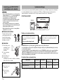
Thank you for selecting this Yamaha product.
Please read the following operating precautions before use.
Yamaha will not be held responsible for any damage and/or
injury caused by not following the cautions below.
• To assure the finest performance, please read this manual
carefully. Keep it in a safe place for future reference.
• Install this unit in a cool, dry, clean place - away from
windows, heat sources, sources of excessive vibration, dust,
moisture and cold. Avoid sources of humming
(transformers, motors). To prevent fire or electrical shock,
do not expose this unit to rain or water.
• The voltage to be used must be the same as that specified on
the rear panel. Using this unit with a higher voltage than
specified is dangerous and may cause a fire and/or electric
shock.
• Do not use force on switches, controls or connection wires.
When moving the unit, first disconnect the power plug and
the wires connected to other equipment. Never pull the
wires themselves.
• When not planning to use this unit for a long period (ie.,
vacation, etc.), disconnect the AC power plug from the wall
outlet.
• To prevent lightning damage, disconnect the AC power plug
when there is an electric storm.
• Since this unit has a built-in power amplifier, heat will
radiate from the rear panel. Place the unit apart from the
walls, allowing at least 20 cm of space above, behind and on
both sides of the unit to prevent fire or damage.
Furthermore, do not position with the rear panel facing
down on the floor or other surfaces.
• Do not cover the rear panel of this unit with a newspaper, a
tablecloth, a curtain, etc., in order not to obstruct heat
radiation. If the temperature inside the unit rises, it may
cause fire, damage to the unit and/or personal injury.
• Do not place the following objects on this unit:
- Glass, china, small metallic, etc.
If glass, etc., falls as a result of vibrations and breaks, it
may cause bodily injury.
- A burning candle etc.
If the candle falls as a result of vibration, it may cause fire
and bodily injury.
- A vessel containing water
If the vessel falls as a result of vibration and water spills,
it may cause damage to the speaker, and/or you may get an
electric shock.
• Do not place this unit where foreign material, such as
dripping water. It might cause fire, damage to this unit, and/
or personal injury.
• Never put a hand or a foreign object into the YST port
located on the right side of this unit. When moving this unit,
do not hold the port, as it might cause personal injury and/or
damage to this unit.
• Never place a fragile object near the YST port of this unit. If
the object falls or drops as a result of the air pressure, it may
cause damage to the unit and/or personal injury.
• Never open the cabinet. It might cause an electric shock,
since this unit uses a high voltage. It might also cause
personal injury and/or damage to this unit. If something
drops into the set, contact your dealer.
• When using a humidifier, be sure to avoid condensation
inside this unit by allowing enough space around this unit or
avoiding excess humidification. Condensation might cause
fire, damage to this unit, and/or electric shock.
• Super-bass frequencies reproduced by this unit may cause a
turntable to generate a howling sound. In such a case, move
this unit away from the turntable.
• This unit may be damaged if certain sounds are
continuously output at high volume level. For example, if
20 Hz-100 Hz sine waves from a test disc, bass sounds from
electronic instruments, etc., are continuously output, or
when the stylus of a turntable touches the surface of a disc,
reduce the volume level to prevent this unit from being
damaged.
• If you hear distortion (i.e., unnatural, intermittent “rapping”
or “hammering” sounds) coming from this unit, reduce the
volume level. Extremely loud playing of a movie
soundtrack’s low frequency, bass-heavy sounds or similarly
loud popular music passages can damage this speaker
system.
• Vibration generated by super-bass frequencies may distort
images on a TV. In such a case, move this unit away from
the TV set.
• Do not attempt to clean this unit with chemical solvents as
this might damage the finish. Use a clean, dry cloth.
• Be sure to read the “TROUBLESHOOTING” section
regarding common operating errors before concluding that
the unit is faulty.
• Install this unit near the wall outlet and where the AC power
plug can be reached easily.
• Secure placement or installation is the owner’s
responsibility. Yamaha shall not be liable for any
accident caused by improper placement or installation
of speakers.
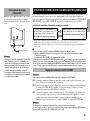
CAUTION: Read this before operating your unit
WARNING
TO REDUCE THE RISK OF FIRE OR ELECTRIC SHOCK, DO
NOT EXPOSE THIS APPLIANCE TO RAIN OR MOISTURE.
This unit is not disconnected from the AC power source as
long as it is connected to the wall outlet, even if this unit
itself is turned off. In this state, this unit is designed to
consume a very small quantity of power.

ii En
English
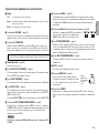
For U.K. customers
If the socket outlets in the home are not suitable for the plug
supplied with this appliance, it should be cut off and an
appropriate 3 pin plug fitted. For details, refer to the
instructions described below.
Note: The plug severed from the mains lead must be
destroyed, as a plug with bared flexible cord is hazardous if
engaged in a live socket outlet.
SPECIAL INSTRUCTIONS FOR U.K. MODEL
FEATURES......................................................................1
SUPPLIED ACCESSORY..............................................1
PLACEMENT .................................................................2
Subwoofer orientation ................................................2
CONTROLS AND THEIR FUNCTIONS.....................3
CONNECTIONS.............................................................5
Connecting to line output (pin jack) terminal(s)
of the amplifier ......................................................5
Connecting to speaker output terminals
of the amplifier ......................................................6
Connecting to the INPUT1/OUTPUT terminals of the
subwoofer
....................................................................7
System connections ....................................................7
Connecting the power cable........................................8
AUTOMATIC POWER-SWITCHING FUNCTION
...........8
Setting the AUTO STANDBY switch........................8
ADJUSTING THE BALANCE......................................9
Subwoofer frequency characteristics........................11
ADVANCED YAMAHA ACTIVE SERVO
TECHNOLOGY II .......................................................12
Twisted Flare Port.........................................................12
TROUBLESHOOTING................................................13
SPECIFICATIONS.......................................................14
IMPORTANT:
THE WIRES IN MAINS LEAD ARE COLOURED IN
ACCORDANCE WITH THE FOLLOWING CODE:
Blue: NEUTRAL
Brown: LIVE
As the colours of the wires in the mains lead of this
apparatus may not correspond with the coloured
markings identifying the terminals in your plug, proceed
as follows: The wire which is coloured BLUE must be
connected to the terminal which is marked with the letter
N or coloured BLACK. The wire which is coloured
BROWN must be connected to the terminal which is
marked with the letter L or coloured RED. Make sure that
neither wire is connected to the earth terminal of a three
pin plug.
Information for Users on Collection and Disposal of Old
Equipment
This symbol on the products, packaging,
and/or accompanying documents means
that used electrical and electronic products
should not be mixed with general
household waste.
For proper treatment, recovery and
recycling of old products, please take them
to applicable collection points, in
accordance with your national legislation
and the Directives 2002/96/EC.
By disposing of these products correctly,
you will help to save valuable resources
and prevent any potential negative effects
on human health and the environment
which could otherwise arise from
inappropriate waste handling.
For more information about collection and
recycling of old products, please contact
your local municipality, your waste
disposal service or the point of sale where
you purchased the items.
[Information on Disposal in other
Countries outside the European Union]
This symbol is only valid in the European
Union. If you wish to discard these items,
please contact your local authorities or
dealer and ask for the correct method of
disposal.
Taking care of the speaker
To maintain the spotless glossy surface of the polished
finish, wipe it with a soft, dry cloth. To avoid damage to the
finish, do not apply chemical solvents, such as alcohol,
benzine, thinner, insecticide, etc. Also, do not use a damp
cloth, or any type of cloth that contains chemical solvents,
or place a plastic or vinyl sheet on top of the speaker.
Otherwise, the finish may peel, the color may fade, or the
sheet may stick to the surface.
Yamaha recommends that you use a Yamaha Unicon cloth
(sold separately). For heavy dirt, use a Yamaha Piano Unicon
(sold separately). You can purchase a Yamaha Unicon cloth
and Piano Unicon at your nearest Yamaha dealer.
CONTENTS
1
2

1 En
• Equipped with the high 1,000 W dynamic power Yamaha digital amplifier
• This subwoofer system employs Advanced Yamaha Active Servo
Technology II for a higher quality super-bass sound.
• Connect with 2 types of input terminals
The subwoofer can be connected through the subwoofer output terminal or the speaker
output terminal, enabling unlimited audio system combinations.
• Achieve the best super-bass sound through controls
For effective use of the subwoofer, the subwoofer’s super-bass sound should be matched
to the sounds of your front speakers. You can create the best sound quality for various
listening conditions by using the HIGH CUT control and the PHASE switch.
• Automatically switch the power to ON/STANDBY
With the AUTO STANDBY (HIGH/LOW/OFF) switch setting, automatically switches
ON/STANDBY by deciphering whether there are signals output from the amplifier. The
Automatic power-switching function saves you the trouble of pressing the ON/
STANDBY button to turn the power on and off.
• The subwoofer can be linked to a Yamaha component for simultaneous
power on/off operation.
Use the supplied system control cable to connect the subwoofer to a Yamaha component
that features a system connector jack. When you turn on or off the power of the
connected component, the subwoofer will also be turned on or off.
• Equipped with the smooth super-bass reproducing Twisted Flare Port
The flared, gently twisting shape diffuses the vortex of air generated around the edge of
the port, creating a smooth flow of air. This reduces extraneous noise not present in the
original input signal, and provides clear, accurate low frequency reproduction.
• Reproduces bass sounds appropriate for the source
The subwoofer can also reproduce a bass sound that is appropriate for the source.
It features a B.A.S.S. switch that enables you to select a bass effect that is suitable for the
source.
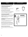
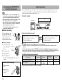
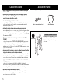
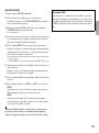
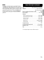
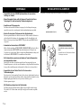
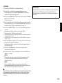
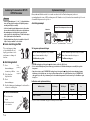
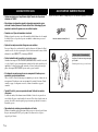
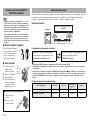
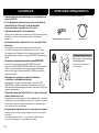
After unpacking, check that the following accessory is contained.
FEATURES SUPPLIED ACCESSORY
Be sure to have another person support it.
The unit may fall and cause injuries.
System control cable (5 m x 1) Power cable
CAUTION
Notes when unpacking

2 En
English
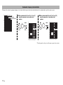
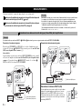
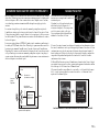
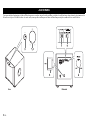
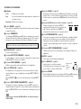
Since the low-end frequencies of audio signals feature long wavelengths, they are almost non-directional to human ears. The super-bass range does not create a stereo image. Therefore,
a single subwoofer may be enough to produce a high-quality super-bass sound. However, using two subwoofers (similarly to L and R front speakers) can enhance your acoustic
experience.
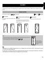
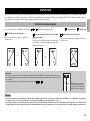
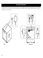
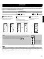
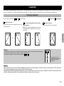
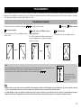
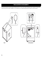
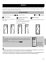
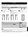
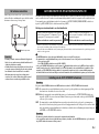
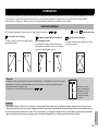
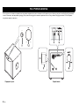
Place the subwoofer as shown in fig. , or for the optimum effect. : subwoofer : front speaker
Using one subwoofer
Place the subwoofer on the outside of either the left or right
front speaker.
Placing the subwoofer in between the left and right
front speakers
If you are placing the subwoofer in between the left and
right front speakers, position it slightly at an angle toward
the wall for better effect.
Using two subwoofers
Place them on the outside of each front speaker.
• Placing the subwoofers too close to a CRT-type TV may impair the picture color or cause a buzzing noise. In this case, place the subwoofers and TV at a separated position where these effects do
not occur. This is not an issue with LCD and plasma TVs.
• If the speaker volume is very loud, furniture or window glass may resonate and the subwoofer itself may vibrate. In this case, lower the volume level. To limit resonance, use a thick curtain or
similar cloth that tends to absorb sound vibrations effectively. Also, changing the subwoofer position may be helpful.
PLACEMENT
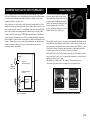
Subwoofer orientation
A
B C
A
or
B
or
C
Note
The placement shown in the figure on the right is also possible. However, if the subwoofer system is placed directly facing a wall, the bass effect
may suffer due to phase cancellation caused by the interference between the direct and reflected sounds.
To prevent this from happening, place the subwoofer system at an angle. (Figures , , and )
A B C
There may be a case that you
cannot obtain enough super-bass
sound from the subwoofer due to
standing waves.
Note

3 En
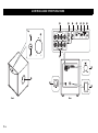
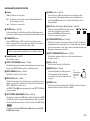
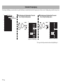
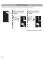
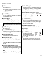
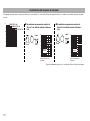
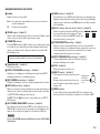
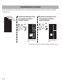
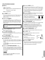
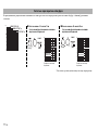
CONTROLS AND THEIR FUNCTIONS
1
2
3
4
Top
Front
5
B
D
C
E
67 8 9@
A
Rear

4 En
English
CONTROLS AND THEIR FUNCTIONS
1 Indicator
2 VOLUME control () page 10)
Adjusts the volume level. Turn the control clockwise to increase the volume, and
counterclockwise to decrease the volume.
3 STANDBY/ON switch
While the POWER switch is ON, press this switch to turn on the power to the
subwoofer. The indicator will light up green. Press the switch again to turn off the
power to the subwoofer. The indicator will turn off.
4 Twisted Flare Port () page 12)
Outputs super-bass sound.
5 OUTPUT (TO SPEAKERS) terminals () page 6)
Can be used for connecting to the main speakers. Signals at the INPUT1 terminals are
sent to these terminals.
6 INPUT2 (NORMAL) terminals () page 5)
Used to input line level signals from the amplifier.
7 INPUT3 (LFE) terminal () page 5)
If your amplifier (or receiver) can cut off high frequencies from signals sent to the
subwoofer, connect the amplifier to the subwoofer’s INPUT3 (LFE) terminal.
The HIGH CUT control D has no effect on signals input to the INPUT 3 LFE terminal.
8 AUTO STANDBY (HIGH/LOW/OFF) switch () page 8)
This switch is originally set to the OFF position. By setting this switch to the HIGH or
LOW position, the subwoofer’s automatic power-switching function operates. If you
do not need this function, leave this switch in the OFF position.
Be sure to set the POWER switch to OFF before you set the AUTO STANDBY switch.
9 PHASE switch () page 10)
This switch is to be set to the REV (reverse) position. However, depending on your speaker
system or listening conditions, there may be a case when better sound quality is obtained by
setting this switch to the NORM (normal) position. Select the best position by ear.
@ B.A.S.S. (Bass Action Selector System) switch () page 10)
When this switch is set to MUSIC, the bass sound in audio
software is well reproduced. When the switch is set to
MOVIE, the bass sound in video software is well reproduced.
A SYSTEM CONNECTOR jack () page 7)
Connect the supplied system control cable here. If you use the system control cable to
connect a subwoofer to a Yamaha component (that features a system connector jack),
turning on or off the power to the connected component automatically turns the
subwoofer on or off.
B INPUT1 (FROM AMPLIFIER) terminals () page 6)
Used to connect the subwoofer with the speaker terminals of the amplifier.
C AC IN () page 8)
Connects the supplied power cable.
D HIGH CUT control () page 9)
Adjusts the high frequency cut off point.
Frequencies higher than the frequency selected by this
control are all cut off (and not output).
E POWER switch
During normal usage, set this switch to ON. If you plan not to use the subwoofer for a long
period of time, set the switch to OFF.
Green:
Red:
Off:
The subwoofer is turned on.
The Automatic power-switching function has activated, and the subwoofer
is in standby mode.
The subwoofer is turned off.
The subwoofer uses a small amount of power in standby mode.
Note
* One graduation
of this control
represents 10 Hz.

5 En
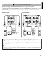
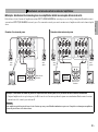
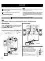
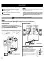
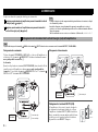
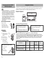
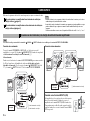
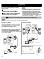
Choose one of the following connection methods most suitable for your audio system.
Choose this method if your amplifier has line output (pin jack) terminal(s).
() page 5)
Choose this method if your amplifier has no line output (pin jack)
terminals. () page 6)
• Unplug the subwoofer and other audio/video components before making connections, and do
not plug them in until all connections are completed.
• Connecting methods and terminal names on your component (such as an amplifier or receiver)
may be different from those used in this book. Please refer to the owner’s manual that came
with your component.
• All connections must be correct, that is to say L (left) to L; R (right) to R; “+” to “+” and “–” to “–”.
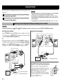
Audio signals input from the /MONO and INPUT 2 terminals on the subwoofer will not be output from the OUTPUT (TO SPEAKERS) terminals.
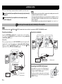
Connecting one subwoofer
Connect the SUBWOOFER (or LOW PASS, etc.) terminal on the rear of the amplifier (or
AV receiver) to the /MONO INPUT2 terminal of the subwoofer using a commercially-
available Mono pin cable (1).
Alternatively,
When connecting the subwoofer to the SPLIT SUBWOOFER terminals (
featuring L and R
channels) on the rear panel of the amplifier, use a commercially-available Audio pin
cable (2) to connect the
/MONO INPUT2 terminal to the “L” side, and the INPUT2
terminal to the “R” side of the SPLIT SUBWOOFER terminals.
Connecting two subwoofers
Connecting to the INPUT3 (LFE) terminal
If your amplifier (or receiver) can cut off high frequencies
from signals sent to the subwoofer, connect the amplifier to
the subwoofer’s INPUT3 (LFE) terminal.
This will promote higher sound quality because the signal
routing in the subwoofer is shortened by bypassing the built-
in HIGH CUT circuit.
CONNECTIONS
1
2
Note
Connecting to line output (pin jack) terminal(s) of the amplifier
1
Note
1
2
1 Mono pin cable
2 Audio pin cable
Subwoofer
Amplifier or
receiver
1
1
Mono pin cable
1
Subwoofer
Subwoofer
Amplifier or
receiver

6 En
English
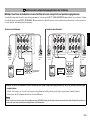
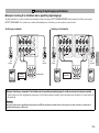
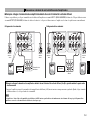
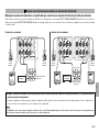
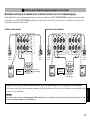
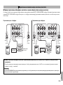
n Example: Connecting the subwoofer to an amplifier that features one set of speaker output terminals
Use speaker cables to connect the speaker output terminals of the amplifier to the subwoofer’s INPUT 1 (FROM AMPLIFIER) terminals. Connect the front speakers to the subwoofer’s
OUTPUT (TO SPEAKERS) terminals. Although the subwoofer is connected between the front speakers and the amplifier, the sound volume or quality will not be affected.
Connecting one subwoofer Connecting two subwoofers
Connecting to speaker output terminals of the amplifier
2
Right front
speaker
Subwoofer
Amplifier or
receiver
Speaker output
terminals
Left front
speaker
Right front
speaker
Left front
speaker
Subwoofer
Speaker output
terminals
Amplifier or
receiver
Subwoofer
n Example: Connecting the subwoofer to an amplifier featuring two sets of speaker output terminals (A and B) that can output sound signals
simultaneously
Set the amplifier so that both sets of speaker output terminals (A and B) will output sound signals simultaneously. Then, connect the front speakers to terminals A, and connect the
subwoofer to terminals B.
If your amplifier features two sets of speaker output terminals that do NOT output sound signals simultaneously, please refer to the example for connecting an amplifier that has only one set of
speaker output terminals (see the figure above).
Note

7 En
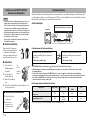
• Make sure that the “+” and “–” polarity markings of the
speaker cables are observed and set correctly. If these cables
are reversed, the sound will be unnatural and lack bass.
• Do not let the bare speaker wires touch each other, because
this could damage the subwoofer or the amplifier.
• If the connections are faulty, no sound will be heard from the
subwoofer or the speakers. Do not insert the insulation into
the hole. Sound may not be produced.
• To avoid accidents resulting from tripping over loose
speaker cables, fix them to the floor.
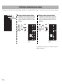
n Before connecting
Remove the insulation at the
tip of the speaker cable, then
twist the core wires together so
that they will not become
disarrayed and short-circuited.
n How to connect
1. Loosen the terminal’s
knob, as shown in the
figure.
2. Insert the bare wire.
3. Tighten the knob.
4. Test the firmness of
the connection by pulling lightly on the cable at the
terminal.
Connecting to the INPUT1/OUTPUT
terminals of the subwoofer
n Connecting the banana plug
1. Tighten the terminal
knob.
2. Simply insert the
banana plug into the
terminal.
Note
15 mm
(5/8")
Good No Good
2
1
3
Red:
positive (+)
Black:
negative (
–)
2
1
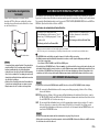
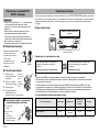
If you use the included system control cable to connect a subwoofer to a Yamaha component (that features a system
connector jack such as a YSP series component or Yamaha receiver), turning on or off the power to the connected
component automatically turns the subwoofer on or off.
Connection example
How the System Connection works
• The POWER switch on the rear panel () page 4) must be set to ON in advance.
• To modify the settings of the connected components, please refer to the owner’s manual that came with the respective
component.
• If the unit is turned off by pressing the STANDBY/ON switch on the front panel () page 4) during system connection, the
indicator (green) gently flashes and notifies you that the connected device is ON. Pressing the STANDBY/ON switch again or
turning the power of the connected component on again turns the unit power ON and the indicator (green) is lit.
The indicator during the system connection
* Lights only when the AUTO STANDBY switch is set to LOW or HIGH.
System connections
Turning on the power to the connected component
will automatically turn on the subwoofer.
* The indicator lights green.
Turning off the power to the connected component
will automatically turn off the subwoofer.
* The indicator turns off.
Indicator status Green light Red light*
Green light
(gentle flashing)
Off
Power of connected component ON ON ON Off
Power of the unit ON
ON
(standby)
Off Off
Subwoofer
Supplied system
control cable
Yamaha YSP series component or receiver

8 En
English
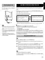
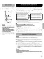
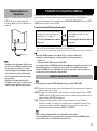
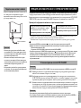
Plug the supplied power cable into the AC IN of this unit
after all other connections are complete, and then plug the
power cable to an AC outlet.
• Do not use other power cables. Use the provided cable. Use of
other power cables may result in fire hazard or electrical
shock.
• Be sure to use the power cable supplied with this unit. Using
a power cable other than the one provided may cause fire or
damage to this unit.
• Do not plug the power cable into the AC outlet of your
amplifier. Doing so may create distorted sounds or turn off
the power of your amplifier.
Connecting the power cable
To AC outlet
Note
This function automatically places the subwoofer in standby mode if the subwoofer does not detect a signal from the
amplifier for a certain period of time. The subwoofer automatically turns on as soon as it detects a signal from the
amplifier.
The Automatic power-switching function works as follows when the AUTO STANDBY (HIGH/LOW/OFF) switch is set
to LOW or HIGH. (Normally, set the switch to LOW.)
How the Automatic power-switching function works
*1
When the Automatic power-switching function is enabled, the subwoofer will detect a bass signal input of below 200Hz (such as sound effects
of explosion in action movies, bass guitar or bass drum sound, etc.).
*2
This value may vary depending on the system environment. For example, it may be affected by noise generated from other equipment.
• The POWER switch on the rear panel () page 4) must be set to ON in advance.
• The Automatic power-switching function can be activated when the following conditions are met:
-The unit is powered ON
-The AUTO STANDBY switch is set to LOW or HIGH
• If the STANDBY/ON switch on the front panel () page 4) is pressed and the unit is turned OFF while the unit is in standby
mode (the indicator is lit in red), the Automatic power-switching function is canceled. Pressing the STANDBY/ON switch again
or turning the power of the component connected via system connection on again turns the unit power ON and the Automatic
power-switching function can be activated again.
Be sure to set the POWER switch to OFF before you set the AUTO STANDBY switch.
LOW: The Automatic power-switching function activates at a certain level of input signal. To enable the function, select
this position.
HIGH:If the Automatic power-switching function does not work well when the AUTO STANDBY switch is set to LOW,
select this position. If the function still does not work, slightly raise the LFE LEVEL on the amplifier.
OFF: The Automatic power-switching function may unexpectedly activate due to the system environment, for example,
if the subwoofer detects noise generated from the peripheral components. In this case, select this position to disable
the Automatic power-switching function, and manually turn the unit on or off by using the POWER switch or the
STANDBY/ON switch.
• The subwoofer uses a small amount of power in auto-standby mode.
• If you plan not to use the subwoofer for a long period of time, set the POWER switch on the rear panel to OFF, or unplug the
power cable from the AC outlet.
AUTOMATIC POWER-SWITCHING FUNCTION
The subwoofer automatically enters standby mode
if it does not receive an input signal (*1) from the
amplifier for 7 or 8 minutes (*2).
* The indicator color changes from green to red.
When the subwoofer detects an input signal (*1)
from the amplifier, the subwoofer automatically
turns on.
* The indicator color changes from red to green.
Setting the AUTO STANDBY switch
Note
Note

9 En
To achieve natural sound with an effective super-bass component, you must adjust the volume and tone balance between the subwoofer and the front speakers. Follow the procedure
described below. If your amplifier or other component connected to the system features subwoofer settings, make the appropriate settings on that component.
ADJUSTING THE BALANCE
Rear panelFront

10 En
English
ADJUSTING THE BALANCE
1. Set the VOLUME control to minimum (0).
2. Turn on the power to the component(s) connected to the subwoofer.
If the component is connected to the subwoofer’s SYSTEM CONNECTOR jack, turn
on the power to that component.
3. Turn the POWER switch ON or press the STANDBY/ON switch to turn on the unit.
* The indicator lights green.
4. Play a source that contains low-frequency components and adjust the output level of
the front speakers using the amplifier’s volume control to the desired listening level.
(Set all tone controls to flat.)
5. Adjust the HIGH CUT control to the position where the desired response can be
obtained.
Normally, set the control to a level a little higher than the front speaker’s rated
minimum reproducible frequency*.
* The front speaker’s rated minimum reproducible frequency can be looked up in the speakers’ catalog
or owner’s manual.
* The HIGH CUT control has no effect on signals input to the INPUT 3 LFE terminal. () page 5)
6. Increase the volume gradually to adjust the volume balance between the subwoofer and
the front speakers.
Normally, set the control to a level where you can obtain a little more bass effect than
when the subwoofer is not used.
7. Set the PHASE switch to the position which yields the more natural (or preferable)
phasing.
8. Set the B.A.S.S. switch to “MOVIE” or “MUSIC” according to the played source.
MOVIE:
When a movie type source is played, the low-frequency effects are enhanced to allow
listeners to enjoy a more powerful sound. (The sound will be richer and deeper.)
MUSIC:
When an ordinary music source is played, the excessive low-frequency components are
cut off to make the sound clearer. (The sound will carry less bass and reproduce the
melody line more clearly.)
Once the volume balance between the subwoofer and the front speakers is adjusted, you can
adjust the volume of your entire sound system by using the amplifier’s volume control.
However, if you replace the front speakers, you will need to make this adjustment again.
PHASE switch
In most situations, set this switch to select the reverse mode. However, depending
on your speaker systems or listening condition, there may be a case when better
sound quality is obtained by selecting the normal mode. Select the better mode by
monitoring the sound.

11 En
The figures below show the optimum adjustment of each control and the frequency characteristics when the subwoofer is combined with a typical front speaker system.
* These diagrams do not depict actual frequency response characteristics.
Subwoofer frequency characteristics
20 50 100 200 500Hz
40
50
60
70
80
90
dB
HIGH CUT 40 Hz
HIGH CUT 90 Hz
HIGH CUT 140 Hz
n When combined with 10 cm (
4"
) or 13 cm (5")
acoustic suspension, 2-way system front
speakers
20 50 100 200 500Hz
40
50
60
70
80
90
dB
NS-SW1000
PHASE
Frequency response graph*
(70 Hz) (REV)
Front
speaker
n When combined with 20 cm (8") or 25 cm (10")
acoustic suspension, 2-way system front
speakers
20 50 100 200 500Hz
40
50
60
70
80
90
dB
NS-SW1000
Frequency response graph*
PHASE
Front
speaker
(50 Hz) (REV)

12 En
English
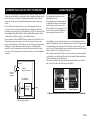
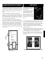
In 1988, Yamaha brought to the marketplace speaker systems utilizing YST (Yamaha
Active Servo Technology) to give powerful, high quality bass reproduction. This technique
uses a direct connection between the amplifier and speaker, allowing accurate signal
transmission and precise speaker control.
As this technology uses speaker units controlled by the negative impedance drive of the
amplifier and resonance generated between the speaker cabinet volume and port, it creates
more resonant energy (the “air woofer” concept) than the standard bass reflex method. This
allows for bass reproduction from much smaller cabinets than was previously possible.
Yamaha’s newly developed Advanced YST II adds many refinements to Yamaha Active
Servo Technology, allowing better control of the forces driving the amplifier and speaker.
From the amplifier’s point of view, the speaker impedance changes depending on the sound
frequency. Yamaha developed a new circuit design combining negative-impedance and
constant-current drives, which provides a more stable performance and clear bass
reproduction, without any murkiness.
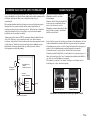
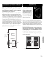
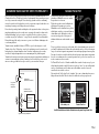
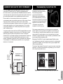
Today’s bass reflex speakers use a Helmholtz
resonator to improve their bass reproduction.
However when reproducing bass that is in the
frequency region of this Helmholtz resonator,
air moves violently in and out through the port
between the interior and exterior of the
speaker, sometimes producing noise due to the
turbulent air flow at the end of the port.
The port and the cabinet resonate at a frequency that is determined by their dimensions and
shape. On the other hand, turbulence in the air flow at the end of the port contains a broad
range of frequency components that are not present in the input signal. This noise occurs
because the broad range of frequency components includes components that match the
resonant frequencies of the port and cabinet, causing strong resonance.
The Twisted Flare Port developed by Yamaha changes the way in which the port widens
toward its end, and also adds a “twist” to suppress airflow turbulence at each end of the port
and thus prevent noise from occurring.
This eliminates the “muddy sound” and “wind noise” that until now have been
characteristic of bass reflex speakers, allowing bass to be reproduced clearly.
ADVANCED YAMAHA ACTIVE SERVO TECHNOLOGY II
High-
amplitude
bass sound
Port
Cabinet
Advanced impedance
Converter
Active Servo
Processing
Amplifier
Signals of low amplitude
Air woofer
(Helmholtz resonator)
Signals
Twisted Flare Port
Conventional Port
Air turbulence on both ends of the port creates noise
Air turbulence is
produced.
Turbulence is
diffused, air flow
becomes smooth.
Twisted Flare Port

13 En
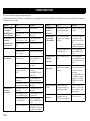
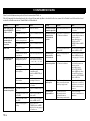
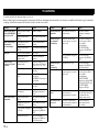
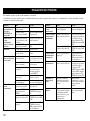
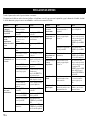
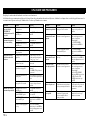
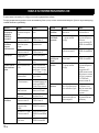
Refer to the chart below if this unit does not function properly.
If the instructions given below do not help, or if the problem you are experiencing is not listed below, turn off the power to the unit, disconnect the power cord and contact an authorized
Yamaha dealer or service center.
TROUBLESHOOTING
Problem Cause What to Do
Power is not supplied
even though the
STANDBY/ON switch
is set the ON position.
The power plug is not securely
connected.
Connect it securely.
The POWER switch is set to the
OFF position.
Set the POWER switch to the
ON position.
The subwoofer does
not turn on
automatically via the
system connection.
The system control cable is not
connected properly or securely.
Connect the system control
cable properly.
The POWER switch is set to
OFF.
Set the POWER switch to ON.
No sound. The volume is set to minimum. Increase the volume.
Speaker cables are not
connected securely.
Connect speaker cables securely.
Low range sound is too
soft or not heard.
Speaker cables are not
connected correctly.
Connect them correctly, that is L
(left) to L; R (right) to R; “+” to
“+” and “–” to “–”.
The PHASE switch is not set
correctly.
Set the PHASE switch to the
other position.
A source sound with little bass
frequency content is being
played.
Play a source sound with bass
frequencies.
Set the HIGH CUT control to a
higher position.
The sound is influenced by
standing waves.
Relocate the subwoofer or
change its positioning angle.
No bass frequency content is
being output from the amplifier.
Check the bass output setting of
the amplifier.
The subwoofer does
not turn on
automatically.
The POWER switch is set to the
OFF position.
Set the POWER switch to the
ON position.
The STANDBY/ON switch is
set to the STANDBY position.
Set the STANDBY/ON switch
to the ON position.
The AUTO STANDBY switch
is set to the OFF position.
Set the AUTO STANDBY
switch to the HIGH or LOW
position.
The level of input signal is too
low.
Set the AUTO STANDBY switch
to the HIGH position, and increase
the output level of the amplifier.
The subwoofer does
not turn on
automatically.
No bass frequency content is
being output from the amplifier.
Check the bass output setting of
the amplifier.
The subwoofer does
not enter standby
mode automatically.
Noise generated from external
appliances etc., is activating the
subwoofer.
Move the subwoofer farther away
from such appliances, and/or
reposition the connected speaker
cables.
Set the AUTO STANDBY switch
to the HIGH or LOW position.
The AUTO STANDBY switch is
set to the OFF position.
Set the AUTO STANDBY
switch to the HIGH or LOW
position.
The subwoofer enters
standby mode
unexpectedly.
The level of input signal is too
low.
Set the AUTO STANDBY
switch to the HIGH position, and
increase the output level of the
amplifier.
The subwoofer turns
on unexpectedly.
Noise generated from external
appliances etc., is activating the
subwoofer.
Move the subwoofer farther
away from such appliances, and/
or reposition the connected
speaker cables.
If the AUTO STANDBY switch
is set to HIGH, set it to LOW.
Alternatively, set the AUTO
STANDBY switch to the OFF
position.
The household breaker
goes off.
This unit consumes much
electricity when a high level
signal is input to this unit.
Turn down the volume on the
amplifier etc. connected to this
unit or cut off the power of other
unused equipment.
An object has fallen
into the port.
Do not try to remove the object.
Attempting to remove the
object may cause a malfunction.
Contact an authorized Yamaha
dealer or service center.
Problem Cause What to Do

14 En
English
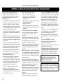
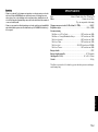
• When an excessive level of signal is input to this unit for 5 to 10 minutes, the POWER indicator
starts flashing alternately in green and red to alarm you of the danger of damaging the power
amplifier and speaker of this unit. If the signal input lasts for 5 minutes more, this unit turns
into the standby mode automatically.
• When an enormous amount of signal is input, the power of this unit is turned off immediately.
To turn on this unit again, press the STANDBY/ON switch on the front panel.
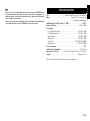
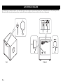
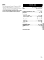
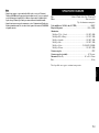
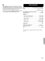
Type..........................................................Advanced Yamaha Active Servo Technology II
Driver .............................................................................30 cm (11-3/4") cone type woofer
Non magnetic shielding type
Amplifier Output (100 Hz, 4 ohms, 10% THD) ................................................. 1,000 W
Frequency Response .................................................................................. 18 Hz - 160 Hz
Power Supply
U.S.A. and Canada models ..................................................................AC 120 V, 60 Hz
U.K. and Europe models......................................................................AC 230 V, 50 Hz
Australia model.................................................................................... AC 240 V, 50 Hz
China model .........................................................................................AC 220 V, 50 Hz
Asia model ...............................................................................AC 220-240 V, 50/60 Hz
Taiwan model.......................................................................................AC 110 V, 60 Hz
Power Consumption................................................................................................. 170 W
Standby Power Consumption .......................................................................0.3 W or less
Dimensions (W × H × D)...................443 × 463 × 522 mm (17-1/2" × 18-1/4" × 20-1/2")
Weight .....................................................................................................42.6 kg (93.9 lbs.)
Please note that all specifications are subject to change without notice.
Note
SPECIFICATIONS

i Fr
Nous vous remercions d’avoir choisi ce produit Yamaha.
Lisez attentivement les précautions d’utilisation suivantes.
Yamaha décline toute responsabilité en cas de dommages
et/ou de blessures découlant du non respect de ces
consignes.
• Pour utiliser l’appareil au mieux de ses possibilités, lisez
attentivement ce mode d’emploi. Conservez-le
soigneusement pour référence.
• Installez cet appareil dans un endroit frais, sec et propre,
à l’écart des fenêtres et à l’abri des sources de chaleur,
des vibrations, de la poussière, de l’humidité et du froid.
Évitez toute source de bruit électrique (transformateurs,
moteurs). Pour éviter un incendie ou une électrocution,
n’exposez pas cet appareil à la pluie ni à l’humidité.
• La tension à utiliser est indiquée sur le panneau arrière.
Il est dangereux d’utiliser cet appareil avec une tension
supérieure à celle spécifiée, car vous risquez de
provoquer un incendie et/ou de vous électrocuter.
• Ne forcez pas sur les prises, les commandes ou les câbles
de connexion. Lorsque vous déplacez cet appareil,
veillez tout d’abord à débrancher la prise et les câbles
connectés à un autre équipement. Ne tirez jamais sur les
câbles mêmes; saisissez toujours leur fiche.
• Si vous n’utilisez pas cet appareil pendant une période
prolongée (par exemple lorsque vous partez en vacances),
débranchez le câble d’alimentation de la prise secteur.
• En cas d’orage, débranchez le câble d’alimentation de la
prise secteur afin de ne pas endommager l’appareil.
• Cet appareil est muni d’un amplificateur de puissance
intégré et dégage donc de la chaleur par son panneau arrière.
N’installez pas l’appareil trop près d’un mur ; laissez au
moins 20 cm au dessus, derrière et sur les côtés afin d’éviter
tout risque d’incendie. Veillez en outre à ne pas placer le
panneau arrière face au sol ou à une autre surface.
• Ne couvrez pas le panneau arrière de cet appareil avec un
journal, une nappe, un rideau, etc., afin d’éviter
l’accumulation de chaleur à l’intérieur de l’appareil.
L’augmentation de la température interne peut
provoquer un incendie ou endommager l’appareil.
• Ne placez pas les objets suivants sur l’appareil :
- Des objets en verre, en porcelaine, de petits objets
métalliques, etc.
Les vibrations risqueraient de faire tomber ces objets et
de causer des blessures.
- Une bougie se consumant, etc.
Si la bougie venait à tomber sous l’effet des vibrations,
cela pourrait provoquer un incendie et des blessures.
- Un récipient contenant de l’eau
Si le récipient venait à tomber sous l’effet des
vibrations et que l’eau se répande, ceci risquerait
d’endommager l’enceinte et/ou de provoquer une
électrocution.
• Évitez de placer cet appareil à proximité de substances
dangereuses. Vous risquez de provoquer un incendie ou
de vous blesser.
• N’introduisez jamais votre main ou un objet dans le port
YST situé sur le côté droit de l’appareil. Lorsque vous
déplacez l’appareil, veillez à ne pas le saisir par ce port ;
vous risquez de vous blesser et/ou d’endommager
l’appareil.
• Ne placez aucun objet fragile à proximité du port YST de
cet appareil. Si l’objet tombe à cause de la pression de
l’air, vous risquez d’endommager l’appareil ou de vous
blesser.
• N’ouvrez le coffret sous aucun prétexte. Vous risquez de
vous électrocuter, car cet appareil fonctionne sous haute
tension. Vous risquez également de vous blesser et/ou
d’endommager l’appareil. Si un objet tombe par mégarde
à l’intérieur de l’appareil, contactez votre revendeur.
• Si vous utilisez un humidificateur, veillez à éviter la
condensation à l’intérieur de l’appareil. Pour cela, laissez
de l’espace autour de l’appareil et évitez une trop forte
humidification. La condensation peut provoquer un
incendie, une électrocution ou endommager l’appareil.
• Les très basses fréquences produites par cet appareil
peuvent provoquer un effet Larsen quand vous utilisez
une platine. Le cas échéant, éloignez l’appareil de la
platine.
• Vous risquez d’endommager l’appareil si certains sons
sont continuellement émis à un volume important. Par
exemple, si vous reproduisez continuellement les ondes
sinusoïdales d’un disque de test comprises entre 20 Hz et
100 Hz ou les graves d’instruments électroniques, ou si
l’aiguille d’une platine touche la surface d’un disque,
réduisez le niveau de volume afin de ne pas endommager
l’appareil.
• Si vous remarquez une distorsion du son (notamment
lorsque le son manque de naturel, ou si des petits coups
secs intermittents ou un “martèlement” se produisent),
diminuez le volume. La reproduction des sons de basses
fréquences de forte intensité contenus dans les bandes
originales de films à un volume excessif risque
d’endommager cette enceinte.
• Les vibrations générées par les très basses fréquences
risquent de déformer les images sur un téléviseur. Le cas
échéant, éloignez l’appareil du téléviseur.
• Ne nettoyez pas l’appareil au moyen de solvants
chimiques, car vous risquez d’endommager la finition.
Utilisez un chiffon propre et sec.
• Lisez attentivement la section “DÉPANNAGE” avant de
conclure que l’appareil est défectueux.
• Installez cet appareil à proximité d’une prise secteur et
dans un endroit où le câble d’alimentation est facilement
accessible.
• L’utilisateur est entièrement responsable de la mise
en place et de l’installation correctes du système.
Yamaha décline toute responsabilité en cas
d’accident provoqué par une mise en place ou une
installation inadéquates de l’enceinte.
ATTENTION: lisez les consignes suivantes avant d’utiliser l’appareil.
AVERTISSEMENT
POUR ÉVITER TOUT RISQUE D’INCENDIE OU
D’ÉLECTROCUTION, N’EXPOSEZ PAS CET APPAREIL
À LA PLUIE OU À L’HUMIDITÉ.

ii Fr
Français
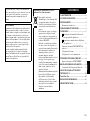
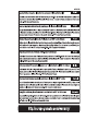
CARACTÉRISTIQUES .................................................1
ACCESSOIRE FOURNI................................................1
DISPOSITION ................................................................2
Orientation du caisson de graves ................................2
PRÉSENTATION DES COMMANDES ET DE
LEURS FONCTIONS .....................................................3
BRANCHEMENTS ........................................................5
Branchement aux bornes de sortie de ligne
(fiches RCA) de l’amplificateur ............................5
Branchement aux bornes de sortie d’enceintes
de l’amplificateur...................................................6
Branchement aux bornes INPUT1/OUTPUT du
caisson de graves
..........................................................7
Connexions système ...................................................7
Raccordement du cordon d’alimentation....................8
FONCTION DE COMMUTATION D’ALIMENTATION
AUTOMATIQUE
...............................................................8
Réglage du commutateur AUTO STANDBY ............8
RÉGLAGE DE BALANCE............................................9
Caractéristiques de fréquence du caisson de
graves........................................................................11
ADVANCED YAMAHA ACTIVE SERVO
TECHNOLOGY II .......................................................12
Twisted Flare Port.........................................................12
DÉPANNAGE................................................................13
CARACTÉRISTIQUES TECHNIQUES....................14
Tant que cet appareil est branché à la prise de courant, il
reste alimenté, même s’il est éteint. L’appareil
consomme donc une faible quantité d’électricité.
Entretien de l’enceinte
Pour conserver intact le brillant de la finition laquée,
essuyez-la avec un chiffon doux et sec. Afin d’éviter
d’endommager la finition, n’utilisez jamais de solvants
chimiques tels que de l’alcool, du benzène, du dissolvant
ou d’autres produits comme de l’insecticide, etc. Veillez
en outre à ne pas utiliser de chiffon humide ni tout type
de chiffon contenant des solvants chimiques; et ne posez
pas de film plastique ou vinyle sur le caisson. Cela
risquerait d’écailler la finition, de décolorer la surface du
caisson ou de provoquer l’adhésion de la feuille.
Yamaha vous recommande d’utiliser un chiffon Yamaha
Unicon (disponible en option). Pour les taches rebelles,
utilisez du produit d’entretien Yamaha Piano Unicon
(disponible en option). Procurez-vous un chiffon
Yamaha Unicon et du produit d’entretien Yamaha Piano
Unicon chez votre revendeur Yamaha.
Information concernant la Collecte et le Traitement
des déchets d’équipements électriques et
électroniques.
Le symbole sur les produits, l’emballage
et/ou les documents joints signifie que
les produits électriques ou électroniques
usagés ne doivent pas être mélangés
avec les déchets domestiques habituels.
Pour un traitement, une récupération et
un recyclage appropriés des déchets
d’équipements électriques et
électroniques, veuillez les déposer aux
points de collecte prévus à cet effet,
conformément à la réglementation
nationale et aux Directives 2002/96/EC.
En vous débarrassant correctement des
déchets d’équipements électriques et
électroniques, vous contribuerez à la
sauvegarde de précieuses ressources et à
la prévention de potentiels effets
négatifs sur la santé humaine qui
pourraient advenir lors d’un traitement
inapproprié des déchets.
Pour plus d’informations à propos de la
collecte et du recyclage des déchets
d’équipements électriques et
électroniques, veuillez contacter votre
municipalité, votre service de traitement
des déchets ou le point de vente où vous
avez acheté les produits.
[Information sur le traitement dans
d’autres pays en dehors de l’Union
Européenne]
Ce symbole est seulement valables dans
l’Union Européenne. Si vous souhaitez
vous débarrasser de déchets
d’équipements électriques et
électroniques, veuillez contacter les
autorités locales ou votre fournisseur et
demander la méthode de traitement
appropriée.
INDEX
1
2

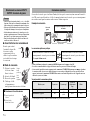
1 Fr
•
Équipé de l’amplificateur numérique Yamaha à puissance dynamique
élevée de 1 000 W
•
Cette enceinte à caisson de graves utilise la technologie Advanced
Yamaha Active Servo Technology II pour une reproduction des très
basses fréquences de meilleure qualité.
•
Raccordement à 2 types de bornes d’entrée
Il est possible de raccorder le caisson de graves en utilisant la borne de sortie du caisson
de graves ou la borne de sortie d’enceintes, ce qui permet un nombre illimité de
combinaisons de systèmes audio.
•
Optimisation des très basses fréquences grâce aux commandes
Pour une utilisation efficace de ce caisson de graves, les très basses fréquences doivent
correspondre au type de son de vos enceintes avant. Il est en outre possible d’optimiser
la qualité sonore suivant les conditions d’écoute au moyen de la commande HIGH CUT
et du commutateur PHASE.
•
Mise sous tension/en veille automatique avec le commutateur ON/
STANDBY
Le réglage du commutateur AUTO STANDBY (HIGH/LOW/OFF) permet de mettre
automatiquement le caisson de graves sous tension/en veille en tentant d’établir si
l’amplificateur émet des signaux. La fonction de commutation d’alimentation
automatique vous évite d’appuyer sur la touche ON/STANDBY pour mettre le caisson
de graves sous et hors tension.
•
Vous pouvez relier le caisson de graves à un élément Yamaha et bénéficier
de la fonction de mise sous/hors tension simultanée.
Le câble de commande système fourni permet de connecter le caisson de graves à un élément
Yamaha équipé d’une prise pour câble de commande système. Quand vous mettez l’élément
raccordé sous/hors tension, le caisson de graves est simultanément mis sous/hors tension.
•
Équipé du Twisted Flare Port, qui reproduit harmonieusement les très
basses fréquences
La forme évasée et légèrement tordue diffuse le tourbillon d’air généré sur la
circonférence de l’évent et produit un flux d’air régulier. Cela réduit les bruits étrangers
perturbant le signal de la source et offre une restitution nette et précise du grave.
•
Reproduction des graves adaptée à la source
Le caisson de graves permet en outre d’adapter la reproduction des graves à la source lue.
Il comporte un commutateur B.A.S.S. qui permet de sélectionner un effet de
reproduction des graves adapté à la source.
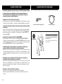
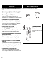
Ouvrez l’emballage et vérifiez qu’il contient les accessoires suivants.
CARACTÉRISTIQUES ACCESSOIRE FOURNI
Demandez de l’aide à quelqu’un pour porter le
caisson de graves.
En cas de chute, l’appareil risque de provoquer
des blessures.
Câble de commande système (5 m x 1) Câble d’alimentation
ATTENTION
Remarques concernant le déballage
Sayfa yükleniyor...
Sayfa yükleniyor...
Sayfa yükleniyor...
Sayfa yükleniyor...
Sayfa yükleniyor...
Sayfa yükleniyor...
Sayfa yükleniyor...
Sayfa yükleniyor...
Sayfa yükleniyor...
Sayfa yükleniyor...
Sayfa yükleniyor...
Sayfa yükleniyor...
Sayfa yükleniyor...
Sayfa yükleniyor...
Sayfa yükleniyor...
Sayfa yükleniyor...
Sayfa yükleniyor...
Sayfa yükleniyor...
Sayfa yükleniyor...
Sayfa yükleniyor...
Sayfa yükleniyor...
Sayfa yükleniyor...
Sayfa yükleniyor...
Sayfa yükleniyor...
Sayfa yükleniyor...
Sayfa yükleniyor...
Sayfa yükleniyor...
Sayfa yükleniyor...
Sayfa yükleniyor...
Sayfa yükleniyor...
Sayfa yükleniyor...
Sayfa yükleniyor...
Sayfa yükleniyor...
Sayfa yükleniyor...
Sayfa yükleniyor...
Sayfa yükleniyor...
Sayfa yükleniyor...
Sayfa yükleniyor...
Sayfa yükleniyor...
Sayfa yükleniyor...
Sayfa yükleniyor...
Sayfa yükleniyor...
Sayfa yükleniyor...
Sayfa yükleniyor...
Sayfa yükleniyor...
Sayfa yükleniyor...
Sayfa yükleniyor...
Sayfa yükleniyor...
Sayfa yükleniyor...
Sayfa yükleniyor...
Sayfa yükleniyor...
Sayfa yükleniyor...
Sayfa yükleniyor...
Sayfa yükleniyor...
Sayfa yükleniyor...
Sayfa yükleniyor...
Sayfa yükleniyor...
Sayfa yükleniyor...
Sayfa yükleniyor...
Sayfa yükleniyor...
Sayfa yükleniyor...
Sayfa yükleniyor...
Sayfa yükleniyor...
Sayfa yükleniyor...
Sayfa yükleniyor...
Sayfa yükleniyor...
Sayfa yükleniyor...
Sayfa yükleniyor...
Sayfa yükleniyor...
Sayfa yükleniyor...
Sayfa yükleniyor...
Sayfa yükleniyor...
Sayfa yükleniyor...
Sayfa yükleniyor...
Sayfa yükleniyor...
Sayfa yükleniyor...
Sayfa yükleniyor...
Sayfa yükleniyor...
Sayfa yükleniyor...
Sayfa yükleniyor...
Sayfa yükleniyor...
Sayfa yükleniyor...
Sayfa yükleniyor...
Sayfa yükleniyor...
Sayfa yükleniyor...
Sayfa yükleniyor...
Sayfa yükleniyor...
Sayfa yükleniyor...
Sayfa yükleniyor...
Sayfa yükleniyor...
Sayfa yükleniyor...
Sayfa yükleniyor...
Sayfa yükleniyor...
Sayfa yükleniyor...
Sayfa yükleniyor...
Sayfa yükleniyor...
Sayfa yükleniyor...
Sayfa yükleniyor...
Sayfa yükleniyor...
Sayfa yükleniyor...
Sayfa yükleniyor...
Sayfa yükleniyor...
Sayfa yükleniyor...
Sayfa yükleniyor...
Sayfa yükleniyor...
Sayfa yükleniyor...
Sayfa yükleniyor...
Sayfa yükleniyor...
Sayfa yükleniyor...
Sayfa yükleniyor...
Sayfa yükleniyor...
-
 1
1
-
 2
2
-
 3
3
-
 4
4
-
 5
5
-
 6
6
-
 7
7
-
 8
8
-
 9
9
-
 10
10
-
 11
11
-
 12
12
-
 13
13
-
 14
14
-
 15
15
-
 16
16
-
 17
17
-
 18
18
-
 19
19
-
 20
20
-
 21
21
-
 22
22
-
 23
23
-
 24
24
-
 25
25
-
 26
26
-
 27
27
-
 28
28
-
 29
29
-
 30
30
-
 31
31
-
 32
32
-
 33
33
-
 34
34
-
 35
35
-
 36
36
-
 37
37
-
 38
38
-
 39
39
-
 40
40
-
 41
41
-
 42
42
-
 43
43
-
 44
44
-
 45
45
-
 46
46
-
 47
47
-
 48
48
-
 49
49
-
 50
50
-
 51
51
-
 52
52
-
 53
53
-
 54
54
-
 55
55
-
 56
56
-
 57
57
-
 58
58
-
 59
59
-
 60
60
-
 61
61
-
 62
62
-
 63
63
-
 64
64
-
 65
65
-
 66
66
-
 67
67
-
 68
68
-
 69
69
-
 70
70
-
 71
71
-
 72
72
-
 73
73
-
 74
74
-
 75
75
-
 76
76
-
 77
77
-
 78
78
-
 79
79
-
 80
80
-
 81
81
-
 82
82
-
 83
83
-
 84
84
-
 85
85
-
 86
86
-
 87
87
-
 88
88
-
 89
89
-
 90
90
-
 91
91
-
 92
92
-
 93
93
-
 94
94
-
 95
95
-
 96
96
-
 97
97
-
 98
98
-
 99
99
-
 100
100
-
 101
101
-
 102
102
-
 103
103
-
 104
104
-
 105
105
-
 106
106
-
 107
107
-
 108
108
-
 109
109
-
 110
110
-
 111
111
-
 112
112
-
 113
113
-
 114
114
-
 115
115
-
 116
116
-
 117
117
-
 118
118
-
 119
119
-
 120
120
-
 121
121
-
 122
122
-
 123
123
-
 124
124
-
 125
125
-
 126
126
-
 127
127
-
 128
128
-
 129
129
-
 130
130
-
 131
131


diğer dillerde
- español: Yamaha NS-SW1000 El manual del propietario
- français: Yamaha NS-SW1000 Le manuel du propriétaire
- italiano: Yamaha NS-SW1000 Manuale del proprietario
- svenska: Yamaha NS-SW1000 Bruksanvisning
- Deutsch: Yamaha NS-SW1000 Bedienungsanleitung
- English: Yamaha NS-SW1000 Owner's manual
- dansk: Yamaha NS-SW1000 Brugervejledning
- русский: Yamaha NS-SW1000 Инструкция по применению
- suomi: Yamaha NS-SW1000 Omistajan opas
- Nederlands: Yamaha NS-SW1000 de handleiding