Yamaha MD4S Kullanım kılavuzu
- Kategori
- Ses mikserleri
- Tip
- Kullanım kılavuzu

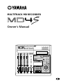
MULTITRACK MD RECORDER
Owner’s Manual
5 / 6 7 / 8
STEREO
MONITOR LEVEL
CUE
STEREO
2TR IN
CUE MIX TO STEREO
MONITOR SELECT
10
9
8
7
6
5
4
3
2
1
0
10
9
8
7
6
5
4
3
2
1
0
TOC WRITE
REHE REC PLAY STOP
PAUSE
IN OUT
SONG SEARCH
LAST REC SEARCH
MARK SEARCHREPEAT
AUTO
PUNCH I/O
AB
DATA CURSOR
PHONES PUNCH I/O
PITCH
EJECT
ADJUST EDIT UTILITY
CH1
BUS
CH2
REC SELECT
CH3 CH4
LRLR
PEAK HOLD DISPLAY
010
MIN MAX
010
MULTITRACK MD RECORDER
IN THRUOUT
MIDI
MIC/LINE INPUT
3
21
4 5678
LINE INPUT
AUX SEND
INSERT
I/O
INSERT
I/O
TRACK
DIRECT OUT
STEREO
OUT
2TR IN MONITOR
OUT
12
1234
EXIT
ENTER
SET
MARK
1
1
GAIN
CUE
HIGH
LINE
FLIP
MIC/
LINE
MIC
LR
010
–15 +15
MID
–15 +15
LOW
–15 +15
PAN
LR
AUX
12
PB
10
9
8
7
6
5
4
3
2
1
0
P
A
N
L
E
V
E
L
2
2
GAIN
CUE
HIGH
LINE
FLIP
MIC/
LINE
MIC
LR
010
–15 +15
MID
–15 +15
LOW
–15 +15
PAN
LR
AUX
12
PB
10
9
8
7
6
5
4
3
2
1
0
P
A
N
L
E
V
E
L
3
3
GAIN
CUE
HIGH
LINE
FLIP
MIC/
LINE
MIC
LR
010
–15 +15
MID
–15 +15
LOW
–15 +15
PAN
LR
AUX
12
PB
10
9
8
7
6
5
4
3
2
1
0
P
A
N
L
E
V
E
L
4
4
GAIN
CUE
HIGH
LINE
FLIP
MIC/
LINE
MIC
LR
010
–15 +15
MID
–15 +15
LOW
–15 +15
PAN
LR
AUX
12
PB
10
9
8
7
6
5
4
3
2
1
0
P
A
N
L
E
V
E
L
E

Laser Diode Properties
* Material : GaAlAs
* Wavelength : 780–790 nm
* Emission Duration : Continuous
* Laser Output Power : Less than 44.6 µW
Laser output is measured at a
distance of 20cm from the object
lens on the optical pick-up head.
(Note)
• On USA or Canadian
models do not have this
label.
• This label is located on
the interior.
• Varningsanvisning för
laserstrålning. Placerad
i apparaten.
CAUTION
VARNING
VARO !
VARNING
VORSICHT!
: INVISIBLE LASER RADIATION WHEN OPEN.
AVOID EXPOSURE TO BEAM.
: OSYNLIG LASERSTRÅLNING NÄR DENNA DEL ÄR
ÖPPEND. STRÅLEN ÄR FARLIG.
: NÄKYMÄTÖNTÄ AVATTAESSA OLET ALTTIINA
LESERSÄTEILYLLE. ÄLÄ KATSO SÄTEESEEN.
: OSYNLIG LASERSTRÅLNING NÄR DENNA DEL ÄR
ÖPPNAD. BETRAKTA EJ STRÅLEN.
: UNSICHTBARE LESERSTRAHLUNG WENN ABDECKUNG
GEÖFFNET. NICHT DEM STRAHL AUSSETZEN.
This unit is classified as a
Class 1 laser product.
This label is located on the
exterior.
CLASS 1 LASER PRODUCT
LUOKAN 1 LASERLAITE
KLASS 1 LASERAPPARAT
Klassmärkning för Finland.
CAUTION
USE OF CONTROLS OR ADJUSTMENTS OR
PERFORMANCE OF PROCEDURES OTHER
THAN THOSE SPECIFIED HEREIN MAY RESULT
IN HAZARDOUS RADIATION EXPOSURE.
ADVARSEL
Usynlig laserstråling ved åbning. Undgå udsaettelse
for stråling.
VAROITUS
Laitteen käyttäminen muulla kuin tässä käyttöohjeesa
mainitulla tavalla saattaa altistaa käyttäjän
turvallisuusluokan 1 ylittävälle näkymättömälle
lasersäteilylle.
VARNING
Om apparaten används på annat sätt än i denna
bruksanvisning specificerats, kan användaren utsättas
för osynlig laserstrålning, som överskrider gränsen för
laserklass 1.
IMPORTANT
Please record the serial number of this unit in the space below.
Serial No.:
The serial number is located on the bottom or rear of the unit.
Retain this Owner's Manual in a safe place for future reference.
IMPORTANT
THE WIRES IN MAINS LEAD ARE COLOURED IN
ACCORDANCE WITH THE FOLLOWING CODE:
BLUE : NEUTRAL
BROWN : LIVE
As the colours of the wires in the mains lead of this apparatus
may not correspond with the coloured markings identifying the
terminals in your plug proceed as follows:
The wire which is coloured BLUE must be connected to the
terminal which is marked with the letter N or coloured BLACK.
The wire which is coloured BROWN must be connected to the
terminal which is marked with the letter L or coloured RED.
Making sure that neither core is connected to the earth terminal of
the three pin plug.
* This applies only to products distributed by YAMAHA KEMBLE
MUSIC (U.K.) LTD.
FCC INFORMATION (U.S.A.)
1. IMPORTANT NOTICE: DO NOT MODIFY THIS UNIT! This product, when
installed as indicated in the instructions contained in this manual, meets FCC
requirements. Modifications not expressly approved by Yamaha may void your
authority, granted by the FCC, to use the product.
2. IMPORTANT: When connecting this product to accessories and/or another
product use only high quality shielded cables. Cable/s supplied with this product
MUST be used. Follow all installation instructions. Failure to follow instructions
could void your FCC authorization to use this product in the USA.
3. NOTE: This product has been tested and found to comply with the requirements
listed in FCC Regulations, Part 15 for Class “B” digital devices. Compliance
with these requirements provides a reasonable level of assurance that your use of
this product in a residential environment will not result in harmful interference
with other electronic devices. This equipment generates/uses radio frequencies
and, if not installed and used according to the instructions found in the users
manual, may cause interference harmful to the operation of other electronic
devices. Compliance with FCC regulations does not guarantee that interference
will not occur in all installations. If this product is found to be the source of
interference, which can be determined by turning the unit “OFF” and “ON”,
please try to eliminate the problem by using one of the following measures:
Relocate either this product or the device that is being affected by the
interference. Utilize power outlets that are on different branch (circuit breaker or
fuse) circuits or install AC line filter/s. In the case of radio or TV interference,
relocate/reorient the antenna. If the antenna lead-in is 300 ohm ribbon lead,
change the lead-in to coaxial type cable. If these corrective measures do not
produce satisfactory results, please contact the local retailer authorized to
distribute this type of product. If you can not locate the appropriate retailer,
please contact Yamaha Corporation of America, Electronic Service Division,
6600 Orangethorpe Ave, Buena Park, CA 90620
The above statements apply ONLY to those products distributed by Yamaha
Corporation of America or its subsidiaries.

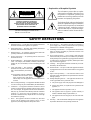
• Explanation of Graphical Symbols
The exclamation point within an equilat-
eral triangle is intended to alert the user to
the presence of important operating and
maintenance (servicing) instructions in the
literature accompanying the product.
The lightning flash with arrowhead symbol
within an equilateral triangle is intended to
alert the user to the presence of uninsulated
“dangerous voltage” within the product’s
enclosure that may be of sufficient magni-
tude to constitute a risk of electric shock to
persons.
10. Power Sources — The appliance should be connected to a
power supply only of the type described in the operating
instructions or as marked on the appliance.
11. Grounding or Polarization — The precautions that should be
taken so that the grounding or polarization means of an
appliance is not defeated.
12. Power-Cord Protection — Power-supply cords should be
routed so that they are not likely to be walked on or pinched by
items placed upon or against them, paying particular attention
to cords at plugs, convenience receptacles, and the point where
they exit from the appliance.
13. Cleaning — The appliance should be cleaned only as recom-
mended by the manufacturer.
14. Nonuse Periods — The power cord of the appliance should be
unplugged from the outlet when left unused for a long period
of time.
15. Object and Liquid Entry — Care should be taken so that
objects do not fall and liquids are not spilled into the enclosure
through openings.
16. Damage Requiring Service — The appliance should be ser-
viced by qualified service personnel when:
A. The power-supply cord or the plug has been damaged; or
B. Objects have fallen, or liquid has been spilled into the
appliance; or
C. The appliance has been exposed to rain; or
D. The appliance does not appear to operate normally or
exhibits a marked change in performance; or
E. The appliance has been dropped, or the enclosure dam-
aged.
17. Servicing — The user should not attempt service the appliance
beyond that described in the operating instructions.
SAFETY INSTRUCTIONS
CAUTION: TO REDUCE THE RISK OF
ELECTRIC SHOCK, DO NOT REMOVE
COVER (OR BACK). NO USER-SERVICEABLE
PARTS INSIDE. REFER SERVICING TO
QUALIFIED SERVICE PERSONNEL.
CAUTION
RISK OF ELECTRIC SHOCK
DO NOT OPEN
1. Read Instructions — All the safety and operating instructions
should be read before the appliance is operated.
2. Retain Instructions — The safety and operating instructions
should be retained for future reference.
3. Heed Warnings — All warnings on the appliance and in the
operating instructions should be adhered to.
4. Follow Instructions — All operating and use instructions
should be followed.
5. Water and Moisture — The appliance should not be used near
water – for example, near a bathtub, washbowl, kitchen sink,
laundry tub, in a wet basement, or near a swimming pool, and
the like.
6. Carts and Stands — The appliance
should be used only with a cart or stand
that is recommended by the manufac-
turer.
6A An appliance and cart combination
should be moved with care. Quick
stops, excessive force, and uneven
surfaces may cause the appliance and cart combination to
overturn.
7. Wall or Ceiling Mounting — The appliance should be mounted
to a wall or ceiling only as recommended by the manufacturer.
8. Ventilation — The appliance should be situated so that its
location or position does not interfere with its proper ventila-
tion. For example, the appliance should not be situated on a
bed, sofa, rug, or similar surface that may block the ventilation
openings; or, placed in a built-in installation, such as a
bookcase or cabinet that may impede the flow of air through
the ventilation openings.
9. Heat — The appliance should be situated away from heat
sources such as radiators, heat registers, stoves, or other
appliances (including amplifiers) that produce heat.
The above warning is located on the
bottom or rear of the unit

4
Important
—Owner’s Manual
Important
Read the Following Before Operating the MD4S
Warnings
• Do not place a container with liquid or small metal objects on top of this unit. Liquid or metal
objects inside this unit are a fire and electrical shock hazard.
• Do not allow water to enter this unit or allow the unit to become wet. Fire or electrical shock
may result.
• Connect this unit is power cord only to an AC outlet of the type stated in this Owner’s Manual
or as marked on the unit. Failure to do so is a fire and electrical shock hazard.
• Do not scratch, bend, twist, pull, or heat the power cord. A damaged power cord is a fire and
electrical shock hazard.
• Do not place heavy objects, including this unit, on top of the power cord. A damaged power
cord is a fire and electrical shock hazard. In particular, be careful not to place heavy objects on
a power cord covered by a carpet.
• If you notice any abnormality, such as smoke, odor, or noise, or if a foreign object or liquid
gets inside the unit, turn it off immediately. Remove the power cord from the AC outlet.
Consult your dealer for repair. Using the unit in this condition is a fire and electrical shock
hazard.
• Should this unit be dropped or the cabinet be damaged, turn the power switch off, remove the
power plug from the AC outlet, and contact your dealer. If you continue using the unit
without heeding this instruction, fire or electrical shock may result.
• If the power cord is damaged (i.e., cut or a bare wire is exposed), ask your dealer for a
replacement. Using the unit with a damaged power cord is a fire and electrical shock hazard.
• Do not remove the unit’s cover. You could receive an electrical shock. If you think internal
inspection, maintenance, or repair is necessary, contact your dealer.
• Do not modify the unit. Doing so is a fire and electrical shock hazard.
• Do not insert or drop metal or flammable objects into the disc loading slot of this unit. Fire or
electrical shock may result.
Cautions
• Allow enough free space around the unit for normal ventilation. This should be: 10 cm at the
sides, and 10 cm behind.
These distances should also be adopted when rack-mounting the unit. For normal ventilation
during use, remove the rear of the rack or open a ventilation hole.
If the airflow is not adequate, the unit will heat up inside and may cause a fire.
• Keep this unit away from the following locations:
— Locations exposed to oil splashes or steam, such as near cooking stoves, humidifiers, etc.
— Unstable surfaces, such as a wobbly table or slope.
— Locations exposed to excessive heat, such as inside a car with all the windows closed, or
places that receive direct sunlight.
— Locations subject to excessive humidity or dust accumulation.
• This unit has ventilation holes at the top, and bottom to prevent the internal temperature
rising too high. Do not block them. Blocked ventilation holes are a fire hazard.

Important
5
—Owner’s Manual
• Turn off all musical instruments, audio equipment, and speakers when connecting to this
unit. Use the correct connecting cables and connect as specified.
• Always lower the volume control to minimum before turning on the power to this unit. A
sudden blast of sound may damage your hearing.
• Hold the power cord plug when disconnecting it from an AC outlet. Never pull the cord. A
damaged power cord is a potential fire and electrical shock hazard.
• Do not touch the power plug with wet hands. Doing so is a potential electrical shock hazard.
• Do not raise the volume of headphones or speakers to a level that makes you feel
uncomfortable. Listening to loud music for long periods can damage your hearing.
• Do not look at the laser beam. You may damage your vision.
Operating Notes
• The digital circuits of this unit may induce a slight noise into nearby radios and TVs. If noise
occurs, relocate the affected equipment.
• XLR-type connectors are wired as follows:
pin 1: ground, pin 2: hot (+), and pin 3: cold (–).
• Insert TRS phone jacks are wired as follows:
sleeve: ground, tip: send, and ring: return.
• The performance of components with moving contacts, such as switches, rotary controls,
faders, and connectors, deteriorates over time. The rate of deterioration depends on the
operating environment and is unavoidable. Consult your dealer about replacing defective
components.
• This unit must not be operated in a tilted position. Doing so can cause malfunctions.
Copyright
© 1998 Yamaha Corporation. All rights reserved.
No part of the MD4S software or this
Owner’s Manual
may be reproduced or distributed in
any form or by any means without the prior written authorization of Yamaha Corporation.
Trademarks:
MD DATA and MiniDisc are trademarks of Sony Corporation.
US and foreign patents licensed from Dolby Laboratories Licensing Corporation.
All other trademarks are the property of their respective holders.
Keep This Manual For Future Reference

6
Contents
—Owner’s Manual
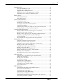
Contents
Welcome to the MD4S......................................... 9
MD4S Features ............................................................................................9
Mixer............................................................................................................ 9
Recorder ...................................................................................................... 9
Buying discs for the MD4S.........................................................................10
MD DATA and MiniDisc .......................................................................... 10
MD4S TOC .................................................................................................11
To update the TOC.................................................................................... 11
Recording modes and recording times......................................................11
MD4S songs and blank areas .....................................................................12
Front and rear panel...................................................................................13
Mono Inputs............................................................................................... 13
Stereo Inputs .............................................................................................. 15
Monitor/Master section............................................................................. 15
Disc transport section................................................................................ 16
Display ........................................................................................................ 19
Top panel connectors ................................................................................ 22
Rear panel................................................................................................... 23
Front panel ................................................................................................. 24
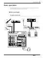
Basic operation.................................................... 25
Before you begin.........................................................................................25
Example connections................................................................................. 25
Turning on the MD4S................................................................................ 26
Inserting a disc ........................................................................................... 26
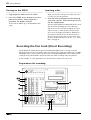
Recording the first track (Direct Recording) ............................................26
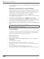
Preparations for recording ........................................................................ 26
Start recording............................................................................................ 28
Overdubbing...............................................................................................30
Mixdown.....................................................................................................32
After completing the Basic Operation section ..........................................34
Advanced recording techniques ......................... 35
Advanced techniques on the MD4S ..........................................................35
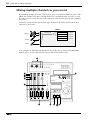
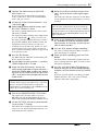
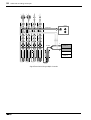
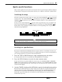
Mixing multiple channels as you record ...................................................36
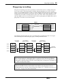
Ping-pong recording ..................................................................................39
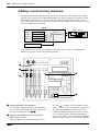
Adding sounds during mixdown...............................................................42

Contents
7
—Owner’s Manual
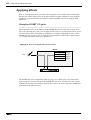
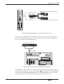
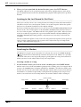
Applying effects...........................................................................................44
Using the INSERT I/O jacks.......................................................................44
Using the AUX SEND jacks .......................................................................46
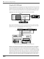
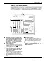
Applying effects during mixdown .............................................................47
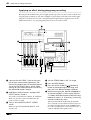
Applying an effect during ping-pong recording .......................................48
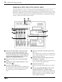
Applying an effect only to the monitor signal...........................................50
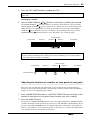
Punch-in/out...............................................................................................52
Manual punch-in/out.................................................................................52
Auto punch-in/out .....................................................................................55
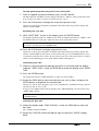
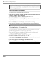
Quick search functions...............................................................................61
Searching for songs.....................................................................................61
Locating to a specified time........................................................................61
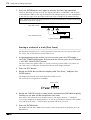
Locating to the Last Record In/Out Point.................................................62
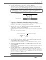
Searching for Markers ................................................................................62
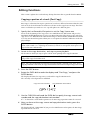
Adjusting the location of a marker or auto punch-in/out point .............63
Erasing a marker or auto punch-in/out point ..........................................65
Various playback functions........................................................................66
Play forward/backward at various speeds (Cue/Review) .........................66
Playback at half speed (x1/2 Play)..............................................................67
Playing a song repeatedly (One Song Repeat/All Song Repeat)...............67
Repeating a specific portion of a song (A-B Repeat)................................68
Cue List playback........................................................................................68
Programming the song playback order (Program Play) ..........................71
Editing functions ........................................................................................73
Copying a portion of a track (Part Copy) .................................................73
Erasing a section of a track (Part Erase)....................................................74
Copying an entire track to another track (Track Copy)...........................75
Erasing an entire track (Track Erase) ........................................................76
Copying/converting a song (Song Copy)..................................................76
Erasing a song (Song Erase) .......................................................................78
Splitting a song into two (Song Divide) ....................................................79
Joining divided songs together (Song Combine)......................................80
Moving a song (Song Move)......................................................................81
Exchanging the order of songs (Song Renumber)....................................82
Other functions...........................................................................................84
Adjusting the record/playback pitch (Pitch function) .............................84
Titling discs and songs................................................................................85
Erasing a disc (Disc Erase) .........................................................................86
Viewing disc contents.................................................................................86
Changing the recording mode ...................................................................87
Adjusting the display brightness................................................................88
Selecting the type of Frame display............................................................88
Using a Foot switch ....................................................................................89
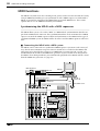
MIDI functions...........................................................................................90
Synchronizing the MD4S with a MIDI sequencer....................................90
About MTC and MIDI Clock ....................................................................91
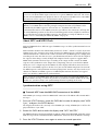
Synchronization using MTC......................................................................91
Synchronization using MIDI Clock...........................................................92
Synchronizing two MD4S recorders..........................................................94
Synchronizing to MTC with a specified offset (time difference).............97
Controlling the MD4S by MMC................................................................98

8
Contents
—Owner’s Manual
Appendix ............................................................ 100
Q&A Section ..............................................................................................100
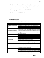
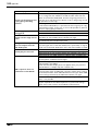
Troubleshooting ........................................................................................101
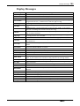
Display Messages
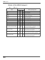
Modes of the MD4S transport ..................................................................104
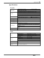
Specifications .............................................................................................105
Recorder .................................................................................................... 105
Mixer.......................................................................................................... 105
General....................................................................................................... 106
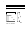
Dimensions................................................................................................ 106
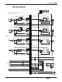
Block Diagram ...........................................................................................107
Glossary......................................................................................................108
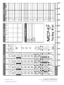
Tempo Map Chart.....................................................................................111
MIDI Implementation Chart .............................. 112
Index................................................................... 113

Welcome to the MD4S
9
—Owner’s Manual
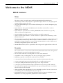
Welcome to the MD4S
MD4S Features
Mixer
The mixer section is an analog mixer with four MIC/LINE and four LINE inputs.
• Continuously variable GAIN controls are provided on input channels 1–4, accepting signals
ranging from mic input to line level.
• Of the four MIC/LINE inputs, two are balanced, allowing the use of either TRS phone plugs
or XLR plugs.
• Input channels 1 and 2 provide INSERT I/O jacks that allow external effects such as a
compressor to be connected.
• Input channels 1–4 provide three-band EQ (HIGH/MID/LOW) that has been specially
engineered for musical applications.
• Two AUX SEND jacks allow external effects such as reverb to be connected.
• Signals sent from input channels 1–4 to the CUE bus (a signal route for monitoring) can be
monitored in stereo.
• The mixer features an in-line design that allows the input signal and the track playback sound
to be controlled simultaneously. While using the CUE bus to monitor each track, you can
make full use of input channels 1–4 as you record. During mixdown, a total of eight sources
(including track playback signals) can be mixed.
• TRACK DIRECT OUT jacks are provided for direct output of the playback from each track.
Recorder
The recorder features a 4-track recorder based on the MD DATA audio format. This provides
many advantages over tape-based multitrack recorders.
• You can choose from three recording modes: 4 track, 2 track, monaural.
• Negligible decrease in audio quality even after repeated ping-pong operations.
• Ping-pong is possible even if all four tracks have been recorded.
• A variety of locate functions allow you to move instantly to any location in the song.
• Accurate auto punch-in/out can be performed with 11.6-millisecond accuracy.
• A variety of editing functions allow you to copy or erase songs and tracks.
• A variety of repeat functions allow songs or portions of a song to be repeated seamlessly.
• The multi-take auto punch-in/out function lets you repeat auto punch-in/out several times,
and select the best take afterward.
• Shuttle playback allows rapid playback / reverse-playback at speeds of 1/2, 2x, 4x, 8x, 16x, or
32x normal speed. (Forward playback only for 1/2 speed.)
• Program Play function lets you program the playback order of songs. In addition, Cue List
Playback lets you freely program the playback order between markers.

10
Welcome to the MD4S
—Owner’s Manual
• The recording/playback pitch can be adjusted up to a maximum of
±
10%. In addition, you
can use the x1/2 play function to playback at half-speed with a pitch that is one octave lower.
• MIDI Time Code (MTC) / MIDI Clock data can be transmitted from the MIDI OUT
connector. This allows synchronization with a MIDI sequencer or rhythm machine without
using up a recording track. In addition, MTC from an external device can be received at the
MIDI IN connector, allowing the MD4S to be synchronized to external video/audio devices.
• MIDI Machine Control (MMC) can be received, allowing the transport of the MD4S to be
controlled from a MIDI sequencer or other external device.
Buying discs for the MD4S
The MD4S can use two types of disc: MD DATA and MiniDisc. MD DATA discs can be used
for 4-track recording/playback, and MiniDiscs can be used for recording/playback of up to
two tracks. (They cannot be used for 4-track recording/playback.)
MD DATA and MiniDisc
MD DATA are widely used for computer data storage, and the MD4S uses the audio format of
this type of disc.
MiniDiscs (also known as MD) are used only for music.
Type
MD DATA MiniDisc
Logo
4-track recording/
playback
Yes (37 minutes per track) No
2-track recording/
playback
Yes (74 minutes) Yes (74 minutes)
Monaural recording/
playback
Yes (148 minutes) Yes (148 minutes)
Notes
• These discs are for computer stor-
age applications, and can be pur-
chased at computer shops. Two
types are available: playback-only
and rewritable. Use the rewritable
type with the MD4S.
• MD DATA discs recorded on the
MD4S cannot be played back on a
conventional MD player.
• MD DATA discs that have been
used to store computer data can-
not be used as is by the MD4S.
Such discs must first be formatted
for audio use. See
“Erasing a disc
(Disc Erase)”
on page 86 for more
information.
• Songs that were recorded in 8-
track mode on a recorder such as
the MD8 cannot be played back
on the MD4S.
• These discs are for music. Two
types are available: playback-only
and rewritable. If you use the
rewritable type, you can record up
to two tracks.
• MiniDiscs recorded on the MD4S
can be played back on a conven-
tional MD player.
• MiniDiscs recorded on a conven-
tional MD recorder can be edited
on the MD4S, but if the music
includes a song that was digitally
copied from a copy-protected
music CD, editing will not be pos-
sible.

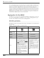
MD4S TOC
11
—Owner’s Manual
MD4S TOC
TOC refers to the Table of Contents area on the disc. The TOC contains information about
what is recorded on the disc, the disc title, song titles, and so on.
When you record a new song or edit the song title, the TOC EDIT indicator of the MD4S will
light to indicate that the TOC needs to be updated.
If the TOC EDIT indicator is lit, you must update the TOC before turning off the power of the
MD4S. If the power is turned off when the TOC EDIT indicator is lit, the data you recorded or
edited will be lost.
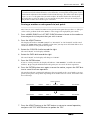
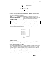
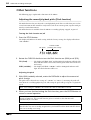
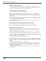
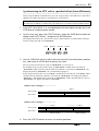
To update the TOC
Press the STOP button, and with the MD4S stopped, press the TOC WRITE button. (The
STOP button and the TOC WRITE button are the same button.)
The display will show “Writing TOC,” indicating that the TOC is being written to disc. When
the TOC has been updated, the “Writing TOC” display and the TOC EDIT indicator will go
dark.
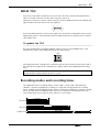
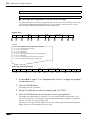
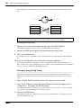
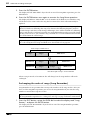
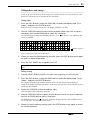
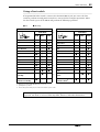
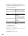
Recording modes and recording times
The MD4S offers three recording modes: 4-track (4TR), 2-track (2TR), and monaural
(MONO). The times available for recording on a single disc will depend on the recording
mode. Available recording/playback times will be 37 minutes in 4TR mode, 74 minutes in 2TR
mode, and 148 minutes in MONO mode. You can use a different recording mode for each
song, which allows you to make the most efficient use of each disc.
Note: If you press the EJECT button while the TOC EDIT indicator is lit, the TOC will
automatically be updated before the disc is ejected.
TOC EDIT
TOC WRITE
STOP
4TR mode
37 minutes
2TR mode
MONO mode
74 minutes
148 minutes

12 Welcome to the MD4S
—Owner’s Manual
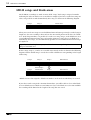
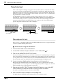
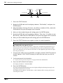
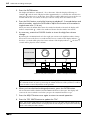
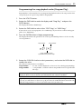
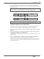
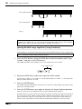
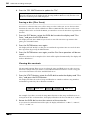
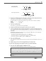
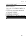
MD4S songs and blank areas
On the MD4S, recordings are made in units called “songs.” Each song is assigned a number
indicating the order in which it was recorded. For example if you have recorded two songs on
a disc, song 2 will be recorded immediately after song 1, as shown in the following diagram.
When you record a new song or record additional material onto a previously-recorded song to
lengthen it, the new recording is done only on the unrecorded portion of the disc; the “blank
area.” In the diagram above, it is possible to record a new song (song 3) in the blank area, or to
record additional material onto song 2 to lengthen it. However since there is no blank area
immediately after song 1, it is not immediately possible to record additional material to song 1
to lengthen it.
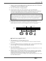
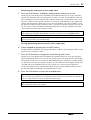
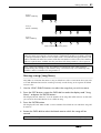
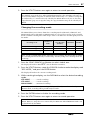
If three songs (songs 1, 2, and 3) are recorded consecutively on disc as shown in the following
diagram, and the middle song is erased, there will be a blank area corresponding to the length
of that song.
* Blank areas are also assigned a “blank area number” in the order in which they are created.
If you then record a song in the situation shown above, you will be able to select either blank
area 1 or blank area 2 in which to record. However if you select blank area 2, the time available
for recording will be limited to the length of the song that was erased.
Tip: If you wish to lengthen song 1, you will need to use a song editing function to move
song 1 to the blank area.
Song 1 Song 2
Blank area 1
Song 1 Song 3Song 2
Blank area 1
Song 1 Song 3Blank area 2
Erase song 2
Blank area 1

Front and rear panel 13
—Owner’s Manual
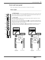
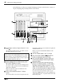
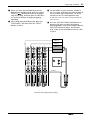
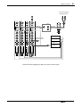
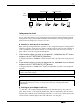
Front and rear panel
This section explains the names and functions of each part of the MD4S.
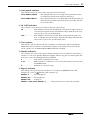
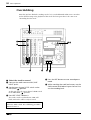
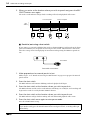
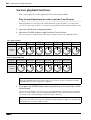
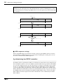
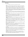
Mono Inputs
A GAIN control
This adjusts the input sensitivity of the MIC/LINE input jack (jacks 1 and 2 on the top
panel). Input channels 1–4 can accommodate signals of any level from mic input to the
line level signals produced by devices such as synthesizers.
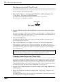
B FLIP switch
This switch selects the signal source for the input channel and the signal source that is
sent to the CUE bus for monitoring.
When this switch is in the MIC/LINE position ( ), the signal from the MIC/LINE jack
will be sent to the input channel, and the track signal (the signal currently being recorded
or played back) will be sent to the CUE bus.
When this switch is in the PB position ( ), the signal from the track will be sent to the
input channel, and the signal from the MIC/LINE jack will be sent to the CUE bus.
1
1
GAIN
CUE
HIGH
LINE
FLIP
MIC/
LINE
MIC
LR
010
–15 +15
MID
–15 +15
LOW
–15 +15
PAN
LR
AUX
12
PB
10
9
8
7
6
5
4
3
2
1
0
P
A
N
L
E
V
E
L
1
2
5
6
7
3
4
GAIN
HIGH
LINE MIC
–15 +15
MID
–15 +15
LOW
–15 +15
CUE
LR
010
P
A
N
L
E
V
E
L
GAIN
HIGH
LINE MIC
–15 +15
MID
–15 +15
LOW
–15 +15
CUE
LR
010
P
A
N
L
E
V
E
L
To the CUE bus To the CUE bus
To the ST bus,
tracks etc.
To the ST bus,
tracks etc.
Signal input to the
MIC/LINE INPUT jack
from an instrument etc.
Signal input to the
MIC/LINE INPUT jack
from an instrument etc.
MD4S
track signal
MD4S
track signal
FLIP
MIC/
LINE
PB
FLIP
MIC/
LINE
PB
When the FLIP
switch is in the
PB position ( )
When the FLIP
switch is in
the MIC/LINE
position ( )

14 Welcome to the MD4S
—Owner’s Manual
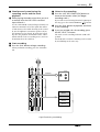
C CUE PAN/CUE LEVEL controls
These two controls adjust the pan and signal level of the signal that is sent to the CUE bus. The
signal that is sent to the CUE bus will depend on the setting of the FLIP switch
2.
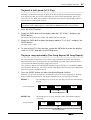
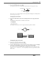
D EQ controls
These controls are used to adjust the high, middle, and low frequency bands. Each can boost
(amplify) or cut (attenuate) the frequency bands shown below over a range of ±15 dB. Each
knob is detented at the 12 o’clock position, which produces a flat response (no boost or cut).
HIGH (high range): 10 kHz (shelving)
MID (mid range): 2.5 kHz (peaking)
LOW (low range): 100 Hz (shelving)
E AUX control
This control sends the signal from the input channel to the AUX SEND jacks. Rotating the
knob toward the “1” position will sent the signal from the input channel to the AUX SEND 1
jack, and rotating the knob toward the “2” position will send the signal to the AUX SEND 2
jack. The knob is detented at the 12 o’clock position, and at this position no signal will be sent
to either AUX SEND jack 1 or 2. The AUX controls are normally used to adjust the signal level
that is sent to external effect devices.
F PAN control
This control adjusts the pan (left/right position) of the input channel signal that is sent to the
ST bus. If you are recording via the ST bus, rotating this control to the L position will assign
the input signal to odd-numbered tracks (tracks 1 and 3), and rotating it to the R position will
assign the input signal to even-numbered tracks (tracks 2 and 4). During mixdown, use this
control to adjust the stereo position of the playback for each track.
G Fader
During recording (when the FLIP switch is at MIC/LINE), use the fader to adjust the input
level of the signal being recorded on the track. During mixdown (when the FLIP switch is at
PB), use the fader to adjust playback level of each track. The fader will be at unity gain when
located between 7 and 8.
Unity gain: This refers to a condition where the output signal and input signal levels are the
same, which will produce the least distortion and the optimal S/N ratio.
Note: The AUX control is “post-fader”; i.e., it adjusts the level of the signal that has passed
through the fader
7. This means that if the fader has been lowered, the AUX control will
have no effect.
Response [dB]
Frequency [Hz]
+5
+10
+15
–15
–10
–5
0
10k1k100 20k20

Front and rear panel 15
—Owner’s Manual
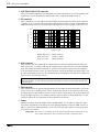
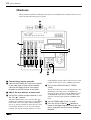
Stereo Inputs
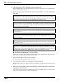
H Level (5/6), (7/8) controls
These controls adjust the level of the signals input from STEREO
INPUT jacks 5/6 or 7/8. These input signals are always sent to the
ST bus, and are mixed with the signals from input channels 1–4
and the playback signals of the tracks.
Monitor/Master section
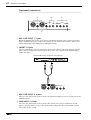
I CUE MIX TO STEREO switch
This switch turns the cue mix function on/off. When the switch is
pressed in ( ), the CUE MIX indicator in the display will light,
and the signal from the CUE bus will be mixed into the ST bus.
The cue mix function can be used only during playback, and is
normally used when adding sounds during mixdown (page 42).
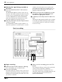
J MONITOR SELECT switches
These switches select the signal that will be monitored from the
MONITOR OUT jacks (rear panel
4) and the PHONES jack
(front panel
1). When the switch is pressed in, the
corresponding source is selected (on). When the switch is up, the
signal will not be selected (off). The three switches can be turned
on/off independently.
2TR IN................... Monitor the signal that is input from the 2TR
IN jacks (rear panel
6).
STEREO ............... Monitor the ST bus signal that is output from
the STEREO OUT jacks (rear panel
5).
CUE....................... Monitor the CUE bus signal.
K MONITOR LEVEL control
This control adjusts the output level of the monitor signal that is
sent to the MONITOR OUT jacks (rear panel
4) and the
PHONES jack (front panel
1).
L STEREO fader
This adjusts the output level of the ST bus that is output from the
STEREO OUT jacks (rear panel
5). The fader will be at unity
gain when located between 7 and 8.
Unity gain: Refer to the explanation of 7 Fader.
5 / 6 7 / 8
010010
8
STEREO
MONITOR LEVEL
CUE
STEREO
2TR IN
CUE MIX TO STEREO
MONITOR SELECT
10
9
8
7
6
5
4
3
2
1
0
10
9
8
7
6
5
4
3
2
1
0
MIN MAX
9
K
L
J

16 Welcome to the MD4S
—Owner’s Manual
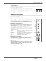
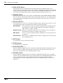
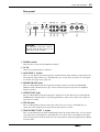
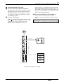
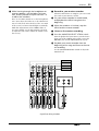
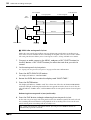
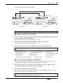
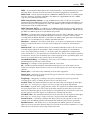
Disc transport section
A Disc transport buttons
REHE button ......This button is used to rehearse punch-in/out. During rehearsal the REHE
indicator located above the button will light, and while rehearsal is paused
the indicator will blink.
REC button.........This button is used to record. When you press the REC button during
playback, recording will begin from that location on any recordable
track(s). (See “Manual punch-in/out” on page 52 for more information.)
The REC indicator located above the button will light during recording,
and will blink to indicate record pause.
PLAY button .......This button is used to begin normal playback, recording, and rehearsal.
After pressing the REHE button, pressing the PLAY button will enter
rehearsal mode. After pressing the REC button, pressing the PLAPY button
will begin recording. If you press the PLAY button without pressing the
REHE or REC button, normal playback will begin. During playback/
recording/rehearsal, the PLAY indicator located above the button will light.
When playback/recording/rehearsal is paused, the PLAY indicator will blink.
PAUSE button....This button temporarily halts (pauses) playback/recording/rehearsal. After
operation has been paused, pressing the PAUSE button once again will
resume playback/recording/rehearsal from that location. If you do not
operate any buttons for about 10 minutes while the unit is in Pause or Rec
Pause mode, the mode will be canceled automatically.
TOC WRITE
REHE REC PLAY STOP
PAUSE
IN OUT
SONG SEARCH
LAST REC SEARCH
MARK SEARCHREPEAT
AUTO
PUNCH I/O
AB
DATA CURSOR
PHONES PUNCH I/O
PITCH
EJECT
ADJUST EDIT UTILITY
CH1
BUS
CH2
REC SELECT
CH3 CH4
LRLR
PEAK HOLD DISPLAY
MULTITRACK MD RECORDER
1234
EXIT
ENTER
SET
MARK
L
K
J
M
N
O
P
Q
R
9
6
7
5
8
2
1
3
4
* Please remove the protective film from the panel.
If the film is left on, the adhesive may break down and soil the unit.

Front and rear panel 17
—Owner’s Manual
STOP/TOC WRITE button........... This button stops playback/recording/rehearsal. When
stopped, this button functions as the TOC WRITE button
to update the TOC (page 11).
B AUTO PUNCH I/O button
This button turns the auto punch-in/out function on/off. When auto punch-in/out is on, the
auto punch indicator in the display (display
K) will light.
C SONG SEARCH [ ]/[ ] buttons
These buttons search for the starting locations of songs or blank areas. They are used to search
for and move to the beginning of songs.
D A B repeat button
This button sets the A and B points of the A-B repeat function (page 68).
E LAST REC SEARCH [IN]/[OUT], SET buttons
The LAST REC SEARCH [IN]/[OUT] buttons locate to the points at which recording or
rehearsal were last started (last record IN point) or last ended (last record OUT point). In
conjunction with the SET button, these buttons can be used to specify any desired location in
a song as the last record in/out point (punch-in/out point).
F REPEAT button
This button is used to select functions such as “one song repeat” which repeatedly plays back a
single song, or “all song repeat” which repeatedly plays back all songs on the disc, and is also
used to switch the repeat function on/off. The repeat indicator (display
O) will light to
indicate the repeat function that is selected.
G MARK SEARCH [ ]/[ ], MARK buttons
The MARK SEARCH buttons are used to locate to the Start marker (beginning of the song),
End marker (end of the song), or to markers that you can set at desired locations in the song.
The MARK button is used to insert a marker into the desired location of a song.
H Disc compartment
An MD DATA or MiniDisc can be inserted here.
I BUS button
This button is used in conjunction with the REC SELECT buttons J to specify the tracks on
which the ST bus signal will be recorded.
J REC SELECT buttons
These buttons select/defeat recording tracks. Tracks selected for recording will be indicated by
the track record indicators (display
J) in the display.
When you press only a REC SELECT button
Recording will be enabled for the corresponding track, and the signal from input channels 1–
4 will be sent directly to the track (direct recording).
When you hold down the BUS button and press a REC SELECT button
Recording will be enabled for the corresponding track. The L channel of the ST bus will be
sent to tracks 1 and 3, and the R channel of the ST bus signal will be sent to tracks 2 and 4.
K EJECT button
This button ejects the disc from the MD4S. If you press the EJECT button while the TOC
EDIT indicator (display
1) is lit, the TOC will be updated before the disc is ejected.

18 Welcome to the MD4S
—Owner’s Manual
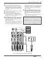
L PEAK HOLD button
This button turns the peak hold function on/off. When the peak hold function is on, a
segment of the track/stereo level meters will remain lit to indicate the maximum level that was
reached. When the peak hold function is on, pressing the PEAK HOLD button once again will
turn off the peak hold function, and the segment that had remained lit will be reset.
M DISPLAY button
This button selects the time counter mode (ELAPSE TIME / TOTAL TIME / REMAIN TIME).
The selected time counter mode will be shown in the display (display
5). If a tempo map has
been programmed for the MD4S, this button will switch the time counter between measure/
beat/clock displays.
N Function buttons
These buttons are used to access a variety of functions. When a button is pressed to access the
corresponding function, the indicator located above the button will light.
PITCH button......Selects functions to adjust the pitch for playback and recording (page 84).
According to the setting, the pitch indicator in the display will indicate
“FIX” (fixed) or “VARI” (variable).
ADJUST button..Allows you to make fine adjustments to the markers or last recording in/
out points that you have set within a song (page 63).
EDIT button ........Accesses a variety of editing functions, and allows you to specify a disc title
or song title.
UTILITY button...Allows you to use MIDI functions, adjust the display contrast, and change
the recording mode etc.
O EXIT button
Use this button to cancel a function or mode.
P ENTER button
Use this button to set functions.
Q DATA dial (DATA+ –)
When the MD4S is stopped or paused, rotating the DATA dial will move through the song in
frame steps. When editing various functions (when one of the function buttons has been
pressed), the DATA dial is used to modify parameter values.
R CURSOR shuttle
When the MD4S is stopped or paused, rotating the CURSOR shuttle allows you to rapidly
rewind or fast-forward through the song. During playback, the CURSOR shuttle allows you to
review (play backward) or cue (play forward) at a variety of speeds (Shuttle playback
functions: page 66). While editing various functions, the CURSOR shuttle is used to select
parameters.

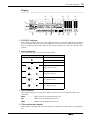
Front and rear panel 19
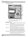
—Owner’s Manual
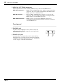
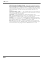
Display
A TOC EDIT indicator
This indicator will light when the TOC (table of contents) needs to be updated, such as after a
new recording or edit. If the power of the MD4S is turned off while the TOC EDIT indicator is
lit, the recorded or edited content may be lost. When you update the TOC, the indicator will
go dark.
B Status indicators
These indicators show the current operating mode.
C Pitch indicator
This indicator shows the current pitch mode. The status of the x1/2 Play function is also
shown here.
HALF..................... Lights when the x1/2 Play function is on.
FIX......................... Lights when the Pitch function is off.
VARI...................... Lights when the Pitch function is on.
D Title and function display
Song numbers, song/disc titles, the currently selected function, or other messages will appear
here.
Indicator Meaning
Normal playback
Cue or Review
Playback is paused
Rehearsal Pause mode
Rehearsal in progress
Record Pause mode
Recording in progress
1 2 3 4 5 6 7 8 9 OUTINE10S
REPEAT A1ALL B
1 2 3 4
1 2 3 4
L R L R
AUTO PUNCH
SINGLE MULTI
MTC FRAMESBEAT SECMEASURE MIN
REMAIN TIMETOTAL TIMEELAPSE TIME
MTC SYNCPITCH
REHE
REC
TOC EDIT
HALF FIX VARI
MASTER SLAVE
MMCMIDI CLK
TRK
DIR
BUS
CLIP
–3
–6
–9
–12
–15
–18
–27
–39
+12
+9
+6
+3
0
–3
–6
–12
–20
STEREO
CUE MIX
dB
L R
SONG NO.
REC MODE
STEP NO.
` 1 2 3 4 5 6 7 8 9 0
3
2
1
4 5678
9JLNMO K
REHE
REHE
REC
REC

20 Welcome to the MD4S
—Owner’s Manual
E Time counter mode
This indicates the time counter mode that was selected by the DISPLAY button (disc transport
M). However if a tempo map has been programmed and the time counter is showing
measure/beat/clock, all of these indicators will be dark.
ELAPSE TIME......The time counter will show the current elapsed time within the song.
TOTAL TIME.........The time counter will show the time position within the entire disc.
REMAIN TIME......The time counter will show the remaining time within the son
F MIDI indicators
The status of various MIDI functions is shown here.
MTC SYNC MASTER ..........This will light when you enable MTC transmission. In this case,
the MD4S will transmit MTC and will function as the master of
a synchronized MIDI system.
MTC SYNC SLAVE..............This will light when you enable MTC reception. In this case, the
MD4S will receive MTC and will function as a slave in a
synchronized MIDI system.
MIDI CLK ..............This will light when you enable MIDI Clock transmission. In this case, the
MD4S will transmit MIDI Clock and will function as the master of a
synchronized MIDI system.
MMC......................This will light when you enable MMC (MIDI Machine Control) reception.
In this case, the MD4S can be controlled from an external device such as a
MIDI sequencer.
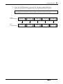
G Track level meters
These indicate the recording/playback level of each track. The range from –39 dB to CLIP is
shown in nine steps. The CLIP indicator will light to indicate that digital clipping has
occurred in the signal. If no disc is inserted, these meters will indicate the input levels of input
channels 1–4.
H Stereo level meter
This meter indicates the output level of the STEREO OUT jacks. The range from –20 dB to
+12 dB is shown in nine steps.
I CUE MIX indicator
This indicates the on/off status of the cue mix function. If you record while the cue mix
function is on, this indicator will blink, indicating that the cue mix function has been
temporarily turned off.
J Track recording indicators
These indicate the recording status of each track. When a indicator is blinking, the
corresponding track is ready to record. When recording begins, the blinking indicator will
light solidly.
DIR/1–4 .................These indicate tracks that have been selected for direct recording (in which
the signal from the input channel is recorded directly).
BUS/L, R...............These indicate tracks that have been selected for recording the signal from
the ST bus (L or R channel).
Sayfa yükleniyor...
Sayfa yükleniyor...
Sayfa yükleniyor...
Sayfa yükleniyor...
Sayfa yükleniyor...
Sayfa yükleniyor...
Sayfa yükleniyor...
Sayfa yükleniyor...
Sayfa yükleniyor...
Sayfa yükleniyor...
Sayfa yükleniyor...
Sayfa yükleniyor...
Sayfa yükleniyor...
Sayfa yükleniyor...
Sayfa yükleniyor...
Sayfa yükleniyor...
Sayfa yükleniyor...
Sayfa yükleniyor...
Sayfa yükleniyor...
Sayfa yükleniyor...
Sayfa yükleniyor...
Sayfa yükleniyor...
Sayfa yükleniyor...
Sayfa yükleniyor...
Sayfa yükleniyor...
Sayfa yükleniyor...
Sayfa yükleniyor...
Sayfa yükleniyor...
Sayfa yükleniyor...
Sayfa yükleniyor...
Sayfa yükleniyor...
Sayfa yükleniyor...
Sayfa yükleniyor...
Sayfa yükleniyor...
Sayfa yükleniyor...
Sayfa yükleniyor...
Sayfa yükleniyor...
Sayfa yükleniyor...
Sayfa yükleniyor...
Sayfa yükleniyor...
Sayfa yükleniyor...
Sayfa yükleniyor...
Sayfa yükleniyor...
Sayfa yükleniyor...
Sayfa yükleniyor...
Sayfa yükleniyor...
Sayfa yükleniyor...
Sayfa yükleniyor...
Sayfa yükleniyor...
Sayfa yükleniyor...
Sayfa yükleniyor...
Sayfa yükleniyor...
Sayfa yükleniyor...
Sayfa yükleniyor...
Sayfa yükleniyor...
Sayfa yükleniyor...
Sayfa yükleniyor...
Sayfa yükleniyor...
Sayfa yükleniyor...
Sayfa yükleniyor...
Sayfa yükleniyor...
Sayfa yükleniyor...
Sayfa yükleniyor...
Sayfa yükleniyor...
Sayfa yükleniyor...
Sayfa yükleniyor...
Sayfa yükleniyor...
Sayfa yükleniyor...
Sayfa yükleniyor...
Sayfa yükleniyor...
Sayfa yükleniyor...
Sayfa yükleniyor...
Sayfa yükleniyor...
Sayfa yükleniyor...
Sayfa yükleniyor...
Sayfa yükleniyor...
Sayfa yükleniyor...
Sayfa yükleniyor...
Sayfa yükleniyor...
Sayfa yükleniyor...
Sayfa yükleniyor...
Sayfa yükleniyor...
Sayfa yükleniyor...
Sayfa yükleniyor...
Sayfa yükleniyor...
Sayfa yükleniyor...
Sayfa yükleniyor...
Sayfa yükleniyor...
Sayfa yükleniyor...
Sayfa yükleniyor...
Sayfa yükleniyor...
Sayfa yükleniyor...
Sayfa yükleniyor...
Sayfa yükleniyor...
Sayfa yükleniyor...
-
 1
1
-
 2
2
-
 3
3
-
 4
4
-
 5
5
-
 6
6
-
 7
7
-
 8
8
-
 9
9
-
 10
10
-
 11
11
-
 12
12
-
 13
13
-
 14
14
-
 15
15
-
 16
16
-
 17
17
-
 18
18
-
 19
19
-
 20
20
-
 21
21
-
 22
22
-
 23
23
-
 24
24
-
 25
25
-
 26
26
-
 27
27
-
 28
28
-
 29
29
-
 30
30
-
 31
31
-
 32
32
-
 33
33
-
 34
34
-
 35
35
-
 36
36
-
 37
37
-
 38
38
-
 39
39
-
 40
40
-
 41
41
-
 42
42
-
 43
43
-
 44
44
-
 45
45
-
 46
46
-
 47
47
-
 48
48
-
 49
49
-
 50
50
-
 51
51
-
 52
52
-
 53
53
-
 54
54
-
 55
55
-
 56
56
-
 57
57
-
 58
58
-
 59
59
-
 60
60
-
 61
61
-
 62
62
-
 63
63
-
 64
64
-
 65
65
-
 66
66
-
 67
67
-
 68
68
-
 69
69
-
 70
70
-
 71
71
-
 72
72
-
 73
73
-
 74
74
-
 75
75
-
 76
76
-
 77
77
-
 78
78
-
 79
79
-
 80
80
-
 81
81
-
 82
82
-
 83
83
-
 84
84
-
 85
85
-
 86
86
-
 87
87
-
 88
88
-
 89
89
-
 90
90
-
 91
91
-
 92
92
-
 93
93
-
 94
94
-
 95
95
-
 96
96
-
 97
97
-
 98
98
-
 99
99
-
 100
100
-
 101
101
-
 102
102
-
 103
103
-
 104
104
-
 105
105
-
 106
106
-
 107
107
-
 108
108
-
 109
109
-
 110
110
-
 111
111
-
 112
112
-
 113
113
-
 114
114
-
 115
115


Yamaha MD4S Kullanım kılavuzu
- Kategori
- Ses mikserleri
- Tip
- Kullanım kılavuzu
diğer dillerde
- español: Yamaha MD4S Manual de usuario
- français: Yamaha MD4S Manuel utilisateur
- italiano: Yamaha MD4S Manuale utente
- svenska: Yamaha MD4S Användarmanual
- čeština: Yamaha MD4S Uživatelský manuál
- polski: Yamaha MD4S Instrukcja obsługi
- Deutsch: Yamaha MD4S Benutzerhandbuch
- português: Yamaha MD4S Manual do usuário
- English: Yamaha MD4S User manual
- dansk: Yamaha MD4S Brugermanual
- русский: Yamaha MD4S Руководство пользователя
- Nederlands: Yamaha MD4S Handleiding
- română: Yamaha MD4S Manual de utilizare