5019 100 75164
AKR 904 IX-1
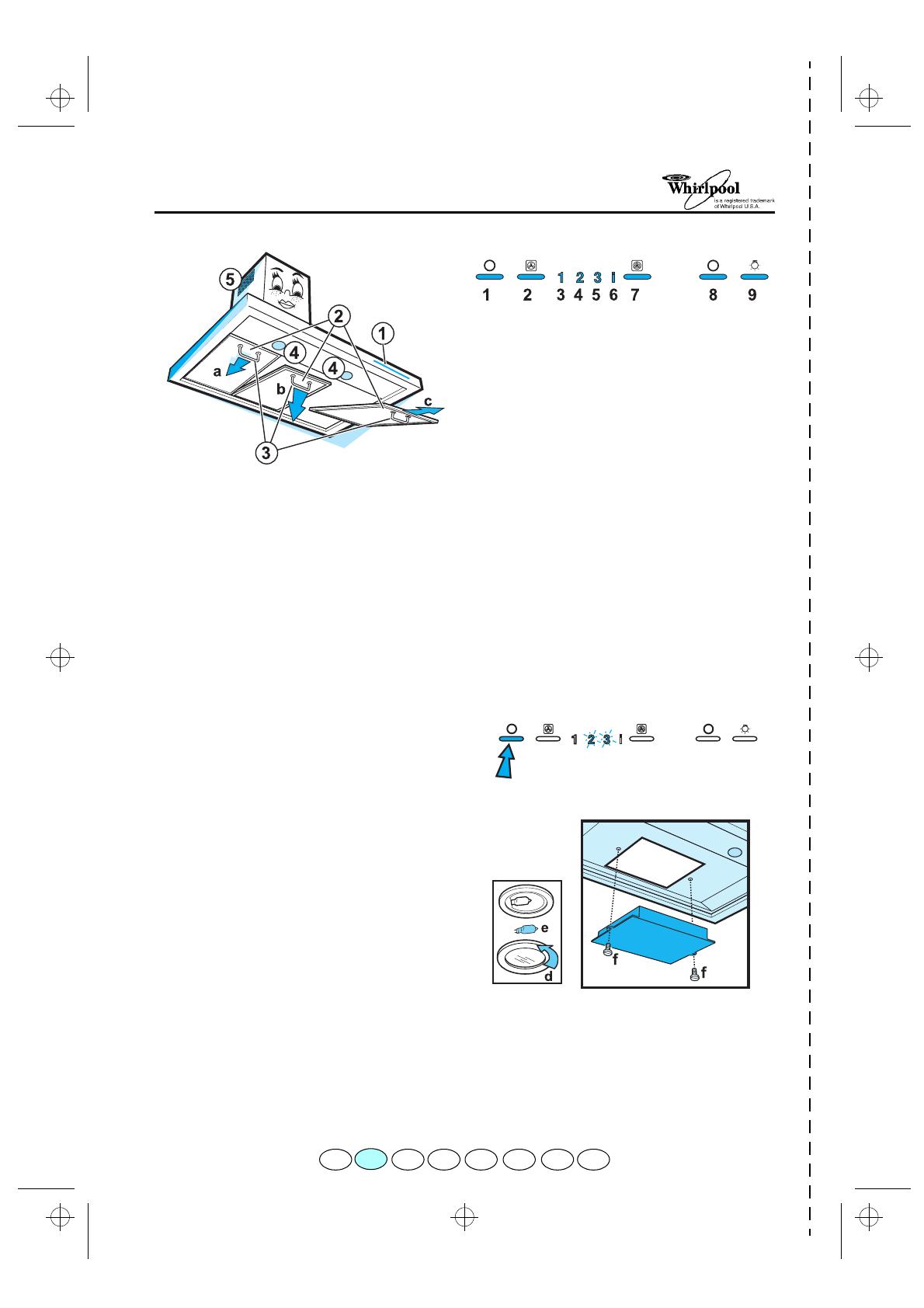
1. Control panel.
2. Grease filters.
3. Grease filter handles.
4. Halogen bulb.
5. Telescopic flue.
Cleaning the grease filter
Wash the grease filter once a month, or
whenever the grease filter saturation indicator
flashes (Extraction speed indicator 2).
1. Unplug the appliance or disconnect the mains
power supply.
2. Remove the grease filters (Fig. 1 - a,b,c).
3. After cleaning the grease filter, remount in
reverse order ensuring the entire extraction
surface is covered.
Replacing bulbs
1. Unplug the appliance or disconnect the mains
power supply.
2. Unscrew the lighting unit (Fig. 2 - d).
3. Remove the burnt-out bulb (Fig. 2 - e).
Replace with 20W max.halogen bulbs only.
4. Screw the lighting unit back in place
Fitting or renewing the carbon filter:
1. Unplug the appliance or disconnect the mains
power supply.
2. Remove the grease filters (Fig. 1 - a,b,c).
3. Fit the carbon filter by fixing it with the two
screws supplied (Fig. 3 - f).
4. If the carbon filter needs renewing, remove
the old filter and fit a new one.
Change the carbon filter once a year and, in
any event, every time the carbon filter
saturation indicator flashes (Extraction speed
indicator 3).
5. Refit the grease filters.
THE CONTROL PANEL
1. Extraction OFF button.
2. Extraction ON speed increase button
- 1
Ö
3
Ö
1......
3. Extraction speed indicator 1.
4. Extraction speed indicator 2 and grease filter
saturation indicator (when flashing).
5. Extraction speed indicator 3 and carbon filter
saturation indicator (when flashing):
this
function is normally deactivated. In order to
activate it press button 1, then buttons 2 and
7 at the same time, until the carbon filter
saturation indicator starts flashing. To
deactivate the function repeat the operation
until the carbon filter saturation indicator
stops flashing.
6. Intensive extraction speed indicator.
7. Timed intensive speed button: the hood
operates at this speed for 5 minutes and then
returns to the previous settings.
This function can be cancelled by pressing
button 1 or 2.
8. Light OFF button.
9. Light ON button.
Reset filter indicator: Press the button OFF
until LED 2 and/or LED 3 stop flashing.
FIG. 1
FIG. 2
FIG. 3
F NL E PGBD IGR
PRODUCT SHEET
75164.fm5 Page 6 Monday, April 10, 2000 1:47 PM


