HOTPOINT/ARISTON TD 641S(BK) IX/HA TR Kullanici rehberi
- Kategori
- Ocaklar
- Tip
- Kullanici rehberi

TD 641S (BK) IX/HA TR
English
Operating Instructions
HOB
Contents
Operating Instructions,1
Warnings,2
Assistance,4
Description of the appliance,5
Installation,6
Start-up and use,10
Precautions and tips,10
Maintenance and care,11
Troubleshooting,11
Türkçe
Kullanım talimatları
SETÜSTÜ
İçindekiler
Kullanım talimatları,1
Uyarı,2
Teknik Servis,4
Cihazın tanıtımı,5
Montaj,12
Başlatma ve kullanım,16
Önlemler ve tavsiyeler,16
Servis ve bakım,17
Arızalar ve çözümler,17

2
Warnings
WARNING: The appliance and its accessible parts
become hot during use. Care should be taken to
avoid touching heating elements. Children less than 8
years of age shall be kept away unless continuously
supervised. This appliance can be used by children
aged from 8 years and above and persons with
reduced physical, sensory or mental capabilities or
lack of experience and knowledge if they have been
given supervision or instruction concerning use of the
appliance in a safe way and understand the hazards
involved. Children shall not play with the appliance.
Cleaning and user maintenance shall not be made
by children without supervision.
WARNING: Unattended cooking on a hob with fat or
oil can be dangerous and may result in re. NEVER
try to extinguish a re with water, but switch off the
appliance and then cover ame e.g. with a lid or a
re blanket.
WARNING: Danger of re: do not store items on the
cooking surfaces.
Never use steam cleaners or pressure cleaners on
the appliance.
Remove any liquid from the lid before opening it. Do
not close the glass cover (if present) when the gas
burners or electric hotplates are still hot.
The appliance is not intended to be operated by
means of an external timer or separate remote
control system.
CAUTION: the use of inappropriate hob guards can
cause accidents.
CAUTION: In case of hotplate glass breakage:
- shut immediately off all burners and any electrical
heating element and isolate the appliance from the
power supply.
- do not touch the appliance surface.
Uyarı
DİKKAT: Bu cihaz ve erişilebilen bölümleri, kullanım
sırasında çok sıcak olur.Dikkat etmek ve ısıtılan
parçalara dokunmaktan kaçınmak gerekir.Eğer
sürekli olarak gözetim altında değiller ise, 8 yaşından
küçük çocukları uzak tutunuz.Bu cihaz, eğer uygun
şekilde gözetim altında bulunuyorlar ise veya güvenli
şekilde cihazın kullanımı hakkında eğitim almışlar
ise ve ilişkin tehlikeler göz önünde bulundurulur ise,
8 yaşından itibaren çocuklar ve ziksel, duyusal
veya mental kapasitelerden yoksun veya tecrübe ve
bilgi sahibi olmayan kişiler tarafından kullanılabilir.
Çocuklar, cihaz ile oynamamalıdır. Temizlik ve bakım
işlemleri, denetimsiz olarak çocuklar tarafından
gerçekleştirilmemelidir.
DİKKAT: Gres yağları ve yağlar ile korumasız küçük
bir fırın bırakmak, tehlikeli olabilir ve bir yangına
neden olabilir. Bir alevi/yangını su ile söndürmeye
çalışmak ASLA gerekmez, ancak cihazı kapatmak
ve örneğin bir kapak veya ateşe dayanıklı bir kapak
ile alevin üzerini örtmek gerekir.
DİKKAT: Yangın riski: pişirme yüzeyleri üzerinde
nesneler bırakmayınız.
Cihazı temizlerken asla buharlı yada yüksek basınçlı
temizleyiciler kullanmayınız.
Açmadan önce, kapağın üzerinde mevcut olan
muhtemel sıvıları temizleyiniz. Cam kapağı (mevcut
olduğu durumlarda) gaz brülörleri ya da elektrikli
levha hala sıcakken kapatmayınız.
Cihaz, harici bir süre ölçer veya ayrı uzaktan bir
kumanda sistemi aracılığıyla çalıştırılmak üzere
tasarlanmamıştır.
DİKKAT: uygun olmayan ocak koruyucularının
kullanılması, kazalara neden olabilir.

3
DİKKAT: Cam ocak düzleminin zarar görmesi halinde:
- tüm brülörleri ve muhtemel elektrikli ısıtma
elemanlarını derhal söndürünüz ve cihazın elektrik
şebekesinden bağlantısını kesiniz.
- cihazın yüzeyine dokunmayınız.

4
Assistance
Communicating:
• the type of problem encountered.
• appliance model (Mod.)
• serial number (S/N)
This information is found on the data plate located on the appliance and/or
on the packaging.
Teknik Servis
şağıdaki bilgileri bildiriniz:
• arıza tipi
• cihazın modeli (Mod.)
• seri numarası (S/N)
Bu bilgiler cihaz ve / veya ambalajı üzerinde bulunan özellik etiketinde bulunur.
-

5
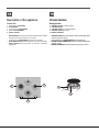
Description of the appliance
Overall view
1. Support Grid for COOKWARE
2. GAS BURNERS
3. Control Knobs for GAS BURNERS
4. Ignition for GAS BURNERS
5. SAFETY DEVICES
• GAS BURNERS differ in size and power. Use the diameter of the cookware
to choose the most appropriate burner to cook with.
• Control Knobs for GAS BURNERS adjust the size of the ame.
• GAS BURNER IGNITION enables a specic burner to be lit automatically.
• SAFETY DEVICE stops the gas flow if the flame is accidentally
extinguished.
Cihazın tanıtımı
Genel görünüm
1. PİŞİRME KAPLARI için destek ızgaraları
2. GAZ BRÜLÖRLERİ
3. GAZ BRÜLÖRLERİ için kumanda düğmeleri
4. GAZ BRÜLÖRLERİ yakma bujisi
5. EMNİYET DÜZENEĞİ
• GAZ BRÜLÖRLERI farklı ebat ve güçlere sahiptir. Kullanacağınız kabın
çapına en uygun olanı seçiniz.
• Alev ayarlanması için GAZ BRÜLÖRLERI kumanda düğmeleri.
• GAZ BRÜLÖRLERI ÇAKMAKLARI seçilmiş olan brülörün otomatik olarak
yakılmasını sağlar.
• EMNIYET DONANIMI alev kazara söndüğünde, gaz çıkışını durdurur.
5
4
2
1
3

6
GB
Installation
! Before operating your new appliance please read this instruction booklet
carefully. It contains important information for safe use, installation and care
of the appliance.
! Please keep these operating instructions for future reference. Pass them on
to possible new owners of the appliance.
Positioning
! Keep packaging material out of the reach of children. It can become a choking
or suffocation hazard (see Precautions and tips).
! The appliance must be installed by a qualied professional according to the
instructions provided. Incorrect installation may cause harm to people and
animals or may damage property.
! This unit may be installed and used only in permanently ventilated rooms
in accordance with current national regulations. The following requirements
must be observed:
• The room must be equipped with an air extraction system that expels
any combustion fumes. This may consist of a hood or an electric fan that
automatically starts each time the appliance is switched on.
In a chimney stack or branched flue.
(exclusively for cooking appliances)
Directly to
the Outside
• The room must also allow proper air circulation, as air is needed for
combustion to occur normally. The ow of air must not be less than 2 m
3
/h
per kW of installed power.
The air circulation system may take air directly
from the outside by means of a pipe with an
inner cross section of at least 100 cm
2
; the
opening must not be vulnerable to any type
of blockages.
The system can also provide the air needed for
combustion indirectly, i.e. from adjacent rooms
tted with air circulation tubes as described
above. However, these rooms must not be
communal rooms, bedrooms or rooms that
may present a re hazard.
• Liquid petroleum gas sinks to the oor as it is heavier than air. Therefore,
rooms containing LPG cylinders must also be equipped with vents to allow
gas to escape in the event of a leak. As a result LPG cylinders, whether
partially or completely full, must not be installed or stored in rooms or
storage areas that are below ground level (cellars, etc.). It is advisable to
keep only the cylinder being used in the room, positioned so that it is not
subject to heat produced by external sources (ovens, replaces, stoves,
etc. ) which could raise the temperature of the cylinder above 50°C.
A
Examples of
ventilation holes
for comburant air.
Enlarging the ventilation slot
between window and floor.
Adjacent
Room
Room to be
Vented
Fitting the appliance
The following precautions must be taken when installing the hob:
• Kitchen cabinets adjacent to the appliance and taller than the top of the
hob must be at least 200 mm from the edge of the hob.
• Hoods must be installed according to their relative installation instruction
manuals and at a minimum distance of 650 mm from the hob (see gure).
• Place the wall cabinets adjacent to the hood at a minimum height of 420
mm from the hob (see gure).
If the hob is installed beneath a wall cabinet,
the latter must be situated at a minimum of 700
mm above the hob.
• The installation cavity should have the dimensions indicated in the gure.
Fastening hooks are provided, allowing you to fasten the hob to tops that
are between 20 and 40 mm thick. To ensure the hob is securely fastened
to the top, we recommend you use all the hooks provided.
555 mm
55 mm
475 mm
• Before fastening the cooktop in place, position the seal (supplied) along
the perimeter of the countertop, as shown in the gure.
Hook fastening diagram
Hooking position for top H=20mm Hooking position for top H=30mm
Front
Hooking position for top H=40mm Back
! Use the hooks contained in the “accessory pack”.
600mm min.
420mm min.
650mm min.

GB
7
• Where the hob is not installed over a built-in oven, a wooden panel must
be installed as insulation. This must be placed at a minimum distance of
20 mm from the lower part of the hob.
Ventilation
To ensure adequate ventilation, the back panel of the cabinet must be
removed. It is advisable to install the oven so that it rests on two strips of
wood, or on a completely at surface with an opening of at least 45 x 560
mm (see diagrams).
560 mm.
45 mm.
! The hob can only be installed above built-in ovens with a cooling ventilation
system.
Electrical connection
Hobs equipped with a three-pole power supply cable are designed to operate
with alternating current at the voltage and frequency indicated on the data
plate (this is located on the lower part of the appliance). The earth wire in the
cable has a green and yellow cover. If the appliance is to be installed above
a built-in electric oven, the electrical connection of the hob and the oven must
be carried out separately, both for electrical safety purposes and to make
extracting the oven easier.
Connecting the supply cable to the mains
Install a standardised plug corresponding to the load indicated on the data
plate.
The appliance must be directly connected to the mains using an omnipolar
circuit-breaker with a minimum contact opening of 3 mm installed between the
appliance and the mains. The circuit-breaker must be suitable for the charge
indicated and must comply with current electrical regulations (the earthing
wire must not be interrupted by the circuit-breaker). The supply cable must
not come into contact with surfaces with temperatures higher than 50°C.
! The installer must ensure that the correct electrical connection has been
made and that it is compliant with safety regulations.
Before connecting to the power supply, make sure that:
• the appliance is earthed and the plug is compliant with the law.
• the socket can withstand the maximum power of the appliance, which is
indicated on the data plate.
• the voltage is in the range between the values indicated on the data plate.
• the socket is compatible with the plug of the appliance. If the socket is
incompatible with the plug, ask an authorised technician to replace it. Do
not use extension cords or multiple sockets.
! Once the appliance has been installed, the power supply cable and the
electrical socket must be easily accessible.
! The cable must not be bent or compressed.
! The cable must be checked regularly and replaced by authorised technicians
only (see Assistance).
! The manufacturer declines any liability should these safety measures not
be observed.
Gas connection
The appliance should be connected to the main gas supply or to a gas
cylinder in compliance with current national regulations. Before carrying out
the connection, make sure the cooker is compatible with the gas supply you
wish to use. If this is not the case, follow the instructions indicated in the
paragraph “Adapting to different types of gas.”
When using liquid gas from a cylinder, install a pressure regulator which
complies with current national regulations.
! Check that the pressure of the gas supply is consistent with the values
indicated in Table 1 (“Burner and nozzle specications”). This will ensure the
safe operation and longevity of your appliance while maintaining efcient
energy consumption.
Connection with a rigid pipe (copper or steel)
! Connection to the gas system must be carried out in such a way as not to
place any strain of any kind on the appliance.
There is an adjustable L-shaped pipe tting on the appliance supply ramp
and this is tted with a seal in order to prevent leaks. The seal must always
be replaced after rotating the pipe tting (seal provided with appliance). The
gas supply pipe tting is a threaded 1/2 gas cylindrical male attachment.
Connecting a flexible jointless stainless steel pipe to a threaded
attachment
The gas supply pipe tting is a threaded 1/2 gas cylindrical male attachment.
These pipes must be installed so that they are never longer than 2000 mm
when fully extended. Once connection has been carried out, make sure that
the exible metal pipe does not touch any moving parts and is not compressed.
! Only use pipes and seals that comply with current national regulations.
Checking the tightness of the connection
! When the installation process is complete, check the pipe ttings for leaks
using a soapy solution. Never use a ame.
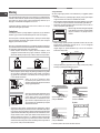
Adapting to different types of gas
To adapt the hob to a different type of gas other than default type (indicated
on the rating plate at the base of the hob or on the packaging), the burner
nozzles should be replaced as follows:
1. Remove the hob grids and slide the burners off their seats.
2. Unscrew the nozzles using a 7 mm socket spanner, and replace them
with nozzles for the new type of gas (see table 1 “Burner and nozzle
characteristics”).
In the case of the Mini WOK burner, use a
spanner with a 7 mm opening to unscrew the
nozzle (see gure).
3. Reassemble the parts following the above procedure in the reverse order.
4. Once this procedure is nished, replace the old rating sticker with one
indicating the new type of gas used. Sticker are available from any of our
Service Centres.
• Adjusting the burners’ primary air
Does not require adjusting.

8
GB
• Setting the burners to minimum
1. Turn the tap to the low ame position;
2. Remove the knob and adjust the adjustment screw, which is positioned
in or next to the tap pin, until the ame is small but steady.
3. Having adjusted the ame to the required low setting, while the burner is
alight, quickly change the position of the knob from minimum to maximum
and vice versa several times, checking that the ame does not go out.
4. Some appliances have a safety device (thermocouple) tted. If the device
fails to work when the burners are set to the low ame setting, increase
this low ame setting using the adjusting screw.
5. Once the adjustment has been made, replace the seals on the by-passes
using sealing wax or a similar substance.
! If the appliance is connected to liquid gas, the regulation screw must be
fastened as tightly as possible.
! Once this procedure is nished, replace the old rating sticker with one
indicating the new type of gas used. Stickers are available from any of our
Service Centres.
! Should the gas pressure used be different (or vary slightly) from the
recommended pressure, a suitable pressure regulator must be tted to the
inlet pipe (in order to comply with current national regulations).
Electrical
connections
DATA PLATE
EU Regulation no. 66/2014 implementing
Directive 2009/125/EC.
standard EN 30-2-1
ECODESIGN
see data plate
This appliance conforms to the following
European Economic Community directives:
- 2006/95/EC dated 12/12/06 (Low Voltage)
and subsequent amendments
- 2004/108/EC dated 15/12/04
(Electromagnetic Compatibility) and
subsequent amendments
- 93/68/EEC dated 22/07/93 and subsequent
amendments.
- 2009/142/EC dated 30/11/06 (Gas) and
subsequent amendments
- 2012/19/EU and subsequent amendments.

GB
9
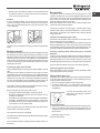
A
S
RR MW
TD 641 S IX/HA TR
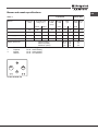
Table 1 Liquid Gas Natural Gas
Nominal (mbar)
Minimum (mbar)
Maximum (mbar)
20
17
25
28-30
20
35
37
25
45
Reduced Rapid (RR)
Semi Rapid (S)
Auxiliary (A)
Mini WOK (MW)
Supply pressures
Burner
Diameter
(mm)
Thermal Power
kW (p.c.s.*)
100
75
55
110
2.60
1.65
1.00
3.50
Nomin. Reduc.
0.70
0.40
0.40
1.30
By-pass
1/100
(mm)
39
28
28
61
Nozzle
1/100
Flow*
g/h
(mm) ***
80
64
50
91
Nozzle
1/100
Flow*
l/h
(mm)
110(Y)
96(Z)
79(6)
138(H)
248
157
95
333
189
120
73
254
**
186
118
71
250
Burner and nozzle specifications
* At 15°C and 1013,25 mbar - dry gas
** Propane P.C.S. = 50.37 MJ/Kg
*** Butane P.C.S. = 49.47 MJ/Kg
Natural P.C.S. = 37.78 MJ/m
3

10
GB
Start-up and use
! The position of the corresponding gas burner is shown on every knob.
Gas burners
Each burner can be adjusted to one of the following settings using the
corresponding control knob:
● Off
Maximum
Minimum
To light one of the burners, hold a lit match or lighter near the burner and, at
the same time, press down and turn the corresponding knob anti-clockwise
to the maximum setting.
Since the burner is tted with a safety device, the knob should be pressed
for approximately 2-3 seconds to allow the automatic device keeping the
ame alight to heat up.
Some models are equipped with an ignition button incorporated into the control
knob. If this is the case, the ignitor is present, but not the button.
To light a burner, simply press the corresponding knob all the way in and
then turn it in the counter-clockwise direction to the “High” setting, keeping
it pressed in until the burner lights.
! If a ame is accidentally extinguished, turn off the control knob and wait for
at least 1 minute before trying to relight it.
To switch off the burner, turn the knob in a clockwise direction until it stops
(when reaches the “●” position).
Practical advice on using the burners
To ensure the burners operate efciently:
• Use appropriate cookware for each burner (see table) so that the ames
do not extend beyond the bottom of the cookware.
• Always use cookware with a at base and a cover.
• When the contents of the pan reach boiling point, turn the knob to minimum.
Reduced Rapid (RR)
Semi Rapid (S)
Auxiliary (A)
Mini Wok (MW)
Ø Cookware diameter (cm)
24 - 26
16 - 20
10 - 14
24 - 26
Burner
To identify the type of burner, refer to the designs in the section entitled, “Burner
and Nozzle Specications”.
Precautions and tips
! This appliance has been designed and manufactured in compliance with
international safety standards. The following warnings are provided for safety
reasons and must be read carefully.
General safety
• This is a class 3 built-in appliance.
• Gas appliances require regular air exchange to maintain efcient
operation. When installing the hob, follow the instructions provided
in the paragraph on “Positioning” the appliance.
• These instructions are only valid for the countries whose symbols
appear in the manual and on the serial number plate.
• The appliance was designed for domestic use inside the home and is not
intended for commercial or industrial use.
• The appliance must not be installed outdoors, even in covered areas. It is
extremely dangerous to leave the appliance exposed to rain and storms.
• Do not touch the appliance with bare feet or with wet or damp hands and
feet.
• The appliance must be used by adults only for the preparation of food,
in accordance with the instructions outlined in this booklet. Any other
use of the appliance (e.g. for heating the room) constitutes improper
use and is dangerous. The manufacturer may not be held liable for
any damage resulting from improper, incorrect and unreasonable
use of the appliance.
• Ensure that the power supply cables of other electrical appliances do not
come into contact with the hot parts of the oven.
• The openings used for ventilation and dispersion of heat must never be
covered.
• Always make sure the knobs are in the “●”/“○” position when the appliance
is not in use.
• When unplugging the appliance always pull the plug from the mains socket,
do not pull on the cable.
• Never carry out any cleaning or maintenance work without having detached
the plug from the mains.
• In case of malfunction, under no circumstances should you attempt to repair
the appliance yourself. Repairs carried out by inexperienced persons may
cause injury or further malfunctioning of the appliance. Contact a Service
Centre (see Assistance).
• Always make sure that pan handles are turned towards the centre of the
hob in order to avoid accidental burns.
• Do not close the glass cover (if present) when the gas burners or electric
hotplates are still hot.
• Do not leave the electric hotplate switched on without a pan placed on it.
• Do not use unstable or deformed pans.
• The appliance should not be operated by people (including children)
with reduced physical, sensory or mental capacities, by inexperienced
individuals or by anyone who is not familiar with the product. These
individuals should, at the very least, be supervised by someone who
assumes responsibility for their safety or receive preliminary instructions
relating to the operation of the appliance.
• Do not let children play with the appliance.
• The appliance is not intended to be operated by means of an external
timer or separate remote-control system.
Disposal
• When disposing of packaging material: observe local legislation so that
the packaging may be reused.
• The European Directive 2012/19/EU on Waste Electrical and Electronic
Equipment (WEEE), requires that old household electrical appliances must
not be disposed of in the normal unsorted municipal waste stream. Old
appliances must be collected separately in order to optimise the recovery
and recycling of the materials they contain and reduce the impact on
human health and the environment.The crossed out “wheeled bin” symbol
on the product reminds you of your obligation, that when you dispose of
the appliance it must be separately collected.
Consumers should contact their local authority or retailer for information
concerning the correct disposal of their old appliance.
Respecting and conserving the environment
• Cook your food in closed pots or pans with well-tting lids and use as little
water as possible. Cooking with the lid off will greatly increase energy
consumption.
• Use purely at pots and pans.

GB
11
• If you are cooking something that takes a long time, it’s worth using a
pressure cooker, which is twice as fast and saves a third of the energy.
Maintenance and care
Switching the appliance off
Disconnect your appliance from the electricity supply before carrying out
any work on it.
Cleaning the appliance
! Do not use abrasive or corrosive detergents such as stain removers, anti-rust
products, powder detergents or sponges with abrasive surfaces: these may
scratch the surface beyond repair.
! Never use steam cleaners or pressure cleaners on the appliance.
• It is usually enough to wash the hob with a damp sponge and dry it with
absorbent kitchen roll.
• The removable parts of the burners should be washed frequently with
warm water and soap and any burnt-on substances removed.
• For hobs which ligth automatically, the terminal part of the electronic instant
lighting devices should be cleaned frequently and the gas outlet holes
should be checked for blockages.
• Stainless steel can be marked by hard water that has been left on the
surface for a long time, or by aggressive detergents containing phosphorus.
After cleaning, rinse and dry any remaining drops of water.
! Do not use stainless steel ame spreaders, bread toasters or meat
grills over gas ames.
Gas tap maintenance
Over time, the taps may become jammed or difcult to turn. If this happens,
the tap must be replaced.
! This procedure must be performed by a qualied technician authorised
by the manufacturer.
Troubleshooting
It may happen that the appliance does not function properly or at all. Before
calling the service centre for assistance, check if anything can be done. First,
check to see that there are no interruptions in the gas and electrical supplies,
and, in particular, that the gas valves for the mains are open.
The burner does not light or the ame is not even around the burner.
Check whether:
• The gas holes on the burner are clogged.
• All the movable parts that make up the burner are mounted correctly.
• There are draughts near the appliance.
The ame dies in models with a safety device.
Check to make sure that:
• You pressed the knob all the way in.
• You keep the knob pressed in long enough to activate the safety device.
• The gas holes are not blocked in the area corresponding to the safety
device.
The burner does not remain lit when set to minimum.
Check to make sure that:
• The gas holes are not blocked.
• There are no draughts near the appliance.
• The minimum setting has been adjusted properly.
The cookware is unstable.
Check to make sure that:
• The bottom of the cookware is perfectly at.
• The cookware is positioned correctly at the centre of the burner.
• The pan support grids have been positioned correctly.
NOTICE

12
TR
Montaj
! Her gerektiğinde başvurulabilmesi için bu el kitapçığının muhafaza edilmesi
önemlidir. Cihazın satılması, başkasına verilmesi ya da taşınması durumunda
yeni kullanıcının işleyiş ve ilişkin uyarılar hakkında bilgi edinmesi için el
kitapçığının cihazla birlikte verildiğinden emin olunuz.
! Talimatları dikkatli bir şekilde okuyunuz: kurulum, kullanım ve emniyet
hakkında önemli bilgiler içermektedir.
Yerleştirme
! Ambalajlar çocukların oyuncağı değildir ve ayrıştırılmış çöp için belirlenen
kurallara uygun olarak imha edilmelidirler (bakınız Önlem ve tavsiyeler).
! Kurulum işlemi bu talimatlar doğrultusunda ve profesyonel olarak kaliye
personel tarafından yapılmalıdır. Hatalı yapılan bir kurulum, insan ve hayvan
sağlığına ya da mala zarar verebilir.
! Bu cihaz, yürürlükteki Ulusal Normlar ve yürürlükteki müteakip güncellemeler
çerçevesinde sadece sürekli olarak havalandırılan mekânlarda monte edilebilir
ve çalıştırılabilir. Aşağıdaki şartlar yerine getirilmelidir:
• Mekân ateşleme dumanlarının dışarıya atılmasını sağlayan, cihaz
açıldığında otomatik olarak devreye giren elektrikli bir vantilatör ya da
davlumbaz vasıtasıyla oluşturulmuş bir tahliye sistemine sahip olmalıdır.
Doğrudan dışarı
atılan dumanlar
Bir baca veya dallı bir boru sistemiyle dışarı
atılan dumanlar (fırın cihazları için saklanmıştır)
• Mekân, ateşleme işleminin düzgün bir şekilde gerçekleşmesi için gerekli
olan hava akımını sağlayacak bir sisteme sahip olmalıdır. Yanma işlemi
için gerekli olan hava miktarı, monte edilmiş olan her kW güç başına 2
m
3
/h’nin altında olmamalıdır.
Sistem, en az 100 cm
2
kesitinde ve istem
dışı tıkanmayacak şekilde kurulu bir boru
vasıtasıyla bina dışından doğrudan hava almak
suretiyle gerçekleştirilebilir.
Veya, dolaylı olarak, bitişik mekânlarda mevcut
olan yukarıda anlatılan türden bir dışarıya
açılma sistemi bulunan bir havalandırma
borusu kullanılabilir; bu havalandırma borusu
gayri menkulün müşterek kullanımında, ya da
yangın tehlikesi olan mekânlarda ya da yatak
odalarında olmamalıdır.
• Sıvılaştırılmış petrol gazları, havadan daha ağır olduklarından, aşağıya
doğru çökerler. Dolayısıyla LPG tüpleri bulunan mekânlarda dışarı açılan
bu pencereler, olası gaz kaçaklarını aşağı kısımdan tahliye edecek şekilde
ayarlanmalıdırlar. Bu nedenle boş ya da kısmen dolu LPG bidonları, zemin
seviyesi altında bulunan mekân yada odalara monte edilmemeli veya
depolanmamalıdırlar (bodrumlar, vb.). Mekânda sadece kullanılmakta
olan tüpü bulundurmak uygundur; ayrıca bu tüp 50°C derece ve üzerindeki
sıcaklık derecelerine ulaşmasına neden olacak doğrudan ısı kaynaklarına
(fırın, şömine, soba) maruz bırakılmamalıdır.
A
Yanıcı hava için
havalandırma açma
Kapı ile döşeme arasındaki
boşluğu arttırma
Bitişik
Oda
Havalandırma
gerektiren oda
Yuvaya oturtmae
Set üstü ocağın doğru şekilde monte edilebilmesi için aşağıdaki şartlara
uyulmalıdır:
• Yan tarafta bulunan ve yüksekliği ocağın çalışma yüzeyini aşan dolaplar
ocağın kenarından en az 200 mm mesafede bulunmalıdır.
• Davlumbazlar kendi talimat kitapçıklarında yer alan özelliklere uygun olarak
ve en az 650 mm boşluk bırakılarak monte edilmelidir (şekle bakınız).
• Davlumbaz yanındaki sarkıkları tezgah zemininden minimum 420 mm
yukarıya yerleştiriniz (şekle bakınız).
Set üstü ocağın bir sarkık altına gelecek şekilde
monte edilmesi durumunda, bu sarkıkın tezgâh
yüzeyine mesafesi en az yaklaşık 700 mm
olmalıdır.
• Mobilya boşluğu şekilde gösterilen boyutlarda olmalıdır. Set üstü ocak
tezgah üzerine yerleştirilmesi amacıyla 20 mm - 40 mm kalınlığında
sabitleme kancaları ile donatılmıştır.
Tezgahı sağlam bir şekilde sabitlemek için mevcut olan kancaların
kullanılması tavsiye edilir.
555 mm
55 mm
475 mm
• Yukarýya sabitlemeye geçmeden önce, contayý (verilmiþ olan) ocaðýn
kenarlarýna þekilde gösterildiði gibi geçiriniz.
Kanca sabitleme şeması
Çalışma tezgahı için kanca Çalışma tezgahı için kanca
pozisyonu H=20mm pozisyonu H=30mm
Ön taraf
Çalışma tezgahı için kanca Arka taraf
pozisyonu H=40mm
! “Aksesuar paketi” nde bulunan kancaları kullanınız.
600mm min.
420mm min.
650mm min.

13
TR
• Set üstü ocağın ankastre fırın üzerine monte edilmemesi durumunda,
izolasyon amacıyla bir ahşap levhanın takılması gerekmektedir. Bu levha
tezgahın alt kısmından en az 20 mm. mesafeye yerleştirilmelidir.
Havalandırma
İyi bir havalandırma sağlanması için yuvanın arka duvarının çıkarılması
gerekir. Fırının kurulumun iki ahşap pervaz üzerine ya da en az 45 x 560
mm ebatlarında bir açıklığı olan bir zemine yaslanacak şekilde yapılması
tercih edilir (şekillere bakınız).
560 mm.
45 mm.
! Setüstü ocak sadece soğutma ve fan sistemi olan ankastre fırın üzerine
yerleştirilebilir.
Elektrik bağlantısı
Üç kutuplu besleme kablosuyla donatılmış set üstü ocaklar, özellikler etiketi
(set üstü ocağın alt kısmına yerleştirilmiştir) üzerinde belirtilmiş olan gerilim
ve besleme frekansı değerlerinde dalgalı akımla çalışacak şekilde üretilmiştir.
Kablonun topraklama iletkeni sarı-yeşil renklerindedir. Setüstü ocağın ankastre
bir fırın üzerine monte edilmesi durumunda, fırın ile ocağın elektrik bağlantısı,
hem elektrik emniyeti açısından hem de fırının çıkarılması gerektiğinde bu
işlemin daha kolay yapılabilmesi amacıyla ayrı ayrı gerçekleştirilmelidir.
Besleme kablosunun şebekeye bağlantısı
Kabloya özellikler etiketi üzerinde belirtilen yüke uygun bir ş monte ediniz.
Şebekeye doğrudan bağlantı yapılması halinde, cihaz ile şebeke arasına
minimum temas aralığı 3 mm olan ve yürürlükteki normlara uygun nitelikte çok
kutuplu bir anahtar takmak gerekmektedir (toprak kablosu elektrik anahtarı
tarafından kesintiye uğratılmamalıdır). Besleme kablosu, hiçbir aşamada ortam
ısısını 50°C geçmeyecek şekilde yerleştirilmelidir.
! Elektrik bağlantısının doğru yapılmasından ve güvenlik kurallarına
uyulmasından kurulumu yapan kişi sorumludur.
Şebekeye bağlamadan önce aşağıdaki durumları kontrol ediniz:
• prizin topraklamasının yürürlükteki normlara uygun olduğunu;
• prizin, cihazın özellikler etiketi üzerinde belirtilen maksimum güç miktarını
destekleyecek şekilde olduğunu;
• besleme geriliminin özellikler etiketi üzerinde belirtilmiş olan değerler
arasında olduğunu;
• cihaz şinin prizle uyumlu olduğunu. Aksi hallerde prizi ya da şi değiştiriniz;
uzatma kabloları ya da çoklu prizler kullanmayınız.
! Cihaz monte edildikten sonra elektrik kablosu ve priz kolay erişilebilecek
yerlerde olmalıdır.
! Kablo kıvrılmalara, bükülmelere veya ezilmelere maruz kalmamalıdır.
! Kablo periyodik olarak kontrol edilmeli ve sadece yetkili teknik personel
tarafından değiştirilmelidir (Destek bölümüne bakınız).
! Bu kurallara uyulmaması halinde rma hiç bir sorumluluk kabul etmez.
Gaz bağlantısı
Cihazın gaz tüpüne yada gaz hattı borusuna bağlanması yürürlükteki
Ulusal Normlara ve müteakip güncellemelere uygun olarak yapılmalı ve
bağlantı öncesi cihazın kullanılacağı gaz tipine ayarlanmış olduğu kontrol
edilmelidir. Aksi takdirde “Farklı gaz tiplerine uyum” paragrafında belirtilen
işlemleri yerine getiriniz. Sıvı gazla, yani gaz tüpünden beslenmesi halinde,
yürürlükteki Ulusal Normalara ve müteakip güncellemelere uygun tipteki
basınç regülatörlerini kullanınız.
! Emniyetli bir çalışma, uygun enerji kullanımı ve cihazın ömrünün uzun olması
için, besleme basıncının tablo 1 “Brülör ve memelerin özellikleri”nde gösterilen
değerler arasında olduğundan emin olunuz.
Sert bir boru ile bağlantı (bakır ya da çelik)
! Gaz tesisatına bağlantı cihazda hiçbir türden zorlama yaratmayacak şekilde
gerçekleştirilmelidir.
Cihazın besleme rampası üzerinde, yönlendirilebilir bir “L” rakoru
bulunmaktadır, bunun sızdırmazlığı da bir conta ile sağlanmıştır. Rakorun
döndürülmesine gerek duyulması halinde, sızdırmazlık contası mutlaka
değiştirilmelidir (cihazla birlikte verilmiştir). Cihazın gaz giriş rakoruna silindirik
1/2 erkek diş açılmıştır.
Paslanmaz çelikten esnek boru ile yivli bağlantı uçları kullanarak yapılan
kesintisiz duvara bağlantı
Cihazın gaz giriş rakoruna silindirik 1/2 erkek diş açılmıştır.
Bu borular, kullanımları sırasında, uzunlukları maksimum 2000 mm’yi
geçmeyecek şekilde döşenmelidir. Bağlantı yapıldığında esnek metal borunun
hareketli parçalar ile temas etmediğinden veya ezilmediğinden emin olunuz.
! Sadece yürürlükteki Ulusal Normlara uygun alüminyum sızdırmaz borular
ve contalar veya kauçuk contalar kullanınız.
Sızdırmazlık kontrolü
! Montaj işlemi tamamlandığında, alev kullanılmadan, yalnız sabunlu su
solüsyonu kullanmak suretiyle tüm rakorlara sızdırmazlık kontrolü yapınız.
Farklı gaz tiplerine uyarlama
Setüstü ocağın üretimde ayarlanmış olduğu gazdan farklı gaz tiplerine
ayarlanması için (ilk ayarı ocağın alt kısmındaki ya da ambalajın üzerindeki
etikette belirtilmiştir), aşağıdaki işlemlerin yapılarak brülörlerin memelerinin
değiştirilmesi gerekir:
1. Ocağın ızgaralarını alınız ve brülörleri yuvalarından çıkartınız.
2. 7 mm’lik bir boru anahtarı kullanarak memeleri sökünüz ve yeni gaz tipine
uyarlanmış olanlarla değiştiriniz (bakınız tablo 1 “Brülör ve memelerin
özellikleri”).
Küçük WOK brülörün enjektörünün
değiştirilmesi için 7 mm’lik açık ağız anahtar
kullanınız (Resme Bakınız).
3. Aynı işlemleri tersine yaparak parçaları tekrar monte ediniz.
4. Bu işlemin sonunda, eski ayarı gösteren etiketi, Teknik Servis
Merkezlerimizden temin edilebilecek, yeni gaz tipini gösteren etiketle
değiştiriniz.
• Brülörlerin birincil hava ayarlanması
Brülörlere ilk hava ayarı yapılmasına gerek yoktur.

14
TR
• Minimum ayarlaması
1. Gaz vanasını minimum konumuna getiriniz;
2. Düğmeyi söküp vana milinin iç tarafında ya da yanında bulunan ayar
vidasına küçük ve düzenli bir alev elde edene kadar müdahale ediniz.
3. Düğmeyi maksimum pozisyondan minimum pozisyona döndürünce
brülörlerin sönmediğinden emin olunuz.
4. Emniyet aygıtı olan cihazlarda (ısı pili), brülörler minimum konumdayken
bu aygıtın çalışmaması durumunda, ayar vidasına müdahale ederek
minimumları yükseltiniz.
5. Ayar işlemi bittiğinde by-pass’lar üzerinde yer alan mumlu ya da benzer
malzemeli mühürleri eski haline getiriniz.
! Sıvı gaz kullanımı halinde ayar vidası sonuna kadar sıkılmalıdır.
! Bu işlemin sonunda, eski ayarı gösteren etiketi, Teknik Servis Merkezlerimizden
temin edilebilecek, yeni gaz tipini gösteren etiketle değiştiriniz.
! Kullanılan gaz basıncının öngörülen basınçtan farklı (ya da değişken)
olması halinde, giriş borusu üzerine uygun bir basınç regülatörü takılmalıdır
(yürürlükteki Ulusal Normlar).
Elektrik
bağlantıları
ÖZELLİKLER ETİKETİ
özellikler etiketine bakınız
Bu cihaz aşağıdaki Avrupa Birliği Direktiflerine
uygundur:
12/12/06 tarihli (Alçak Basınç) 2006/95/CE ve
üzerinde yapılan değişiklikler
- 15/12/04 tarihli (Elektromanyetik Uyum)
2004/108/CE ve üzerinde yapılan değişiklikler
- 22/07/93 tarihli 93/68/CEE ve üzerinde yapılan
değişiklikler.
- 30/11/09 tarihli 2009/142/CE (Gaz) ve
üzerinde yapılan değişiklikler.
2012/19/EU ve üzerinde yapılan değişiklikler.
AEEE Yönetmeliğine uygundur
AB Yönetmelik No.66/2014 tümleyici Yönetmelik
2009/125/EC.
EN 30-2-1 standardı
ECODESIGN

15
TR
A
S
RR MW
TD 641 S IX/HA TR
Çizelge
1
Sıvı gaz
Doğal gaz
Nominal (mbar)
Minimum (mbar)
Maksimum (mbar)
20
17
25
28-30
20
35
37
25
45
Azaltılmış hızlı (RR)
Yarı hızlı (S)
Yardımcı (A)
Mini WOK (MW)
Besleme basýnçlarý
Ocak
Çap
(mm)
Termik güç
kW (p.c.s.*)
100
75
55
110
2.60
1.65
1.00
3.50
Nomin. Reduc.
0.70
0.40
0.40
1.50
By-pass
1/100
(mm)
39
28
28
61
Meme
1/100
Tasima gücü
*
g/
saat
(mm)
***
80
64
50
91
Meme
1/100
Tasima
gücü
*
l/
saat
(mm)
110(Y)
96(Z)
79(6)
138
248
157
95
333
189
120
73
254
**
186
118
71
250
* 15°C ve 1013,25 mbar’da-kuru gaz
** Propan P. C.S. = 50.37 MJ/Kg
*** Bütan P. C.S. = 49.47 MJ/Kg
Doğal P. C.S. = 37.78 MJ/m
3
Brülör ve memelerin özellikleri
TD 641 S IX/HA TR
II2H3+ 8,75 (636 g/h - G30) (625 g/h - G31)
Sınıf
Model
Gaz bölü
mE
lektrik bölümü
220-240V~ 50/60Hz
Feszültség és
frekvencia
Güç (W)
0,6
Nominal güç (kW)

16
TR
Başlatma ve kullanım
! Her bir düğme üzerinde kumanda ettiği gaz brülörünün konumu belirtilmiştir.
Gaz brülörleri
Seçilmiş olan brülör, ilgili düğme vasıtasıyla aşağıdaki konumlara ayarlanabilir:
● Kapalı
Maksimum
Minimum
Ocakların birini yakmak için bir çakmak ya da yakıcı yaklastırınız, basılı
tutarak ilgili dügmeyi maksimum pozisyonuna getirene kadar saatin ters
yönünde döndürünüz.
Emniyet aygıtı mevcut olan modellerde, alevin otomatik olarak yanık kalmasını
saglayan aygıt yanıncaya kadar dügmeyi 2-3 saniye basılı tutmanız gerekir.
Modeller, düğmenin içine entegre yakma sistemi ile donatılmıştır. Seçilmiş
olan brülörü yakmak için öncelikle ilgili düğmeyi basmanız gerekmektedir,
daha sonra maksimum güç pozisyonuna gelene kadar saat yönünün tersinde
döndürünüz ve göz yanana kadar da basılı tutunuz.
! Brülör alevlerinin beklenmedik şekilde sönmesi durumunda kontrol düğmesini
kapatınız ve en az 1 dakika bekledikten sonra tekrar yakmayı deneyiniz.
Brülörü kapatmak için, düğmeyi durana kadar saat yönünde döndürmeniz
gerekmektedir ( “●” sembolüne gelene kadar).
Brülörlerin kullanımı için pratik tavsiyeler
En yüksek performansı elde edebilmek amacıyla aşağıdaki hususları
aklınızdan çıkarmayınız:
• Kapların altından alevlerin çıkmasını önlemek amacıyla her brülöre uygun
kaplar (tabloya bakınız) kullanınız.
• Her zaman altı düz ve kapaklı kaplar kullanınız.
• Kaynama esnasında düğmeyi minimum pozisyona kadar döndürünüz.
Azaltılmış Hızlı (RR)
Yarı Hızlı (S)
Yardımcı (A)
Mini Wok (MW)
Ø Kap çapı (cm)
24 - 26
16 - 20
10 - 14
24 - 26
Brülör
Brülör tipini belirlemek için “Brülör ve memelerin özellikleri” paragragfında
mevcut olan şekillere başvurunuz.
Önlemler ve tavsiyeler
! Cihaz uluslararası emniyet mevzuatlarına uygun olarak projelendirilmiş ve
üretilmiştir. Bu uyarılar güvenlik amaçlı olup dikkatlice okunmalıdır.
Genel emniyet
• Bu cihaz, 3. sınıf ankastre cihazlara dahildir.
• Gazla çalışan cihazlar, düzgün bir çalışma için düzenli hava
değişimine ihtiyaç duyarlar. Montaj sırasında “Yerleştirme”
bölümüne ilişkin paragrafta belirtilmiş olan şartlara uyulduğundan
emin olunuz.
• Verilmiş olan talimatlar sadece kitapçıkta ve sicil plakasında
sembolü bulunan ülkeler için geçerlidir.
• Cihaz, meskenlerde kullanılmak üzere tasarlanmış olup profesyonel
kullanım amaçlı değildir.
• Yağmur ve fırtınaya maruz kalması son derece tehlikeli olduğundan cihaz,
üzeri kapalı bile olsa açık alanlara monte edilemez.
• Cihaza ayaklarınız çıplakken ya da elleriniz veya ayaklarınız ıslak ya da
nemliyken dokunmayınız.
• Cihaz, sadece yetişkin kişiler tarafından ve bu kitapçıkta aktarılan
talimatlara göre, yemek pişirmek amaçlı kullanılmalıdır. Her
türlü diğer kullanımlar (örneğin: ortam ısıtması) uygunsuz ve bu
nedenle tehlikeli bulunur. Üretici rma uygunsuz, hatalı ve mantık
dışı kullanımlardan kaynaklanan muhtemel zararlardan sorumlu
tutulamaz.
• Diğer beyaz eşyalara ait kabloların fırının sıcak kısımlarına temas etmesini
önleyiniz.
• Havalandırma ve ısı dağılma noktalarını tıkamayınız.
• Cihazın kullanılmadığı zamanlarda düğmelerin daima “●”/“○” konumunda
olduğundan emin olunuz.
• Fişi prizden çekerken kablosundan değil şin kendisinden tutarak çekiniz.
• Fişi elektrik şebekesinden çekmeden, temizlik veya bakım müdahalelerinde
bulunmayınız.
• Arıza halinde onarmak amacıyla iç mekanizmaları kurcalamayınız. Teknik
servis ile irtibata geçiniz (Teknik servis bölümüne bakınız).
• Kazayla darbeye maruz kalmalarını önlemek için tencere kulplarının daima
ocağın içine doğru dönük olduğundan emin olunuz.
• Cam kapağı (mevcut olduğu durumlarda) gaz brülörleri ya da elektrikli
levha hala sıcakken kapatmayınız.
• Elektrik levhasını üzerinde tencere olmadan yanık bırakmayınız.
• Yerine oturmayan ya da deforme olmuş tencereleri kullanmayınız.
• Çocuklar, cihaz ile oynamamalıdır
• Cihaz harici bir otomatik zaman ayarı veya ayrı bir uzaktan kumanda
sistemi ile çalıştırılacak şekilde tasarlanmamıştır.
İmha
• Ambalaj malzemelerinin imha edilmesi: ambalajların geri dönüşümünü
sağlayan yerel düzenlemelere uyunuz.
• Elektrik ve elektronik cihazların atıklarını değerlendirme konusunu
düzenleyen 2012/19/UE sayılı Avrupa Birliği mevzuatında; beyaz eşyaların
kentsel katı atık genel yöntemi ile imha edilmemesi öngörülmüştür.
Kullanılmayan cihazlar, madde geri kazanım ve geri dönüşüm oranını
en yüksek seviyeye yükseltmek, çevre ve insan sağlığına olası zararları
engellemek için ayrı ayrı toplanması gerekir. Tüm ürünlerin üzerinde;
ayrıştırılmış atık hükümlerini hatırlatmak amacıyla üstünde çarpı işareti
olan sepet sembolü yer almaktadır.
Kullanılmayan beyaz eşyalar belediye atık toplama servisine teslim
edilebilecektir, bunları belediyenin bunun için özel olarak belirlediği yerlere
ya da konuyla ilgili ulusal düzenlemelerin mevcut olduğu durumlarda,
benzer tipte yeni bir ürün aldığınız satıcılara verebilirsiniz.
Belli başlı tüm beyaz eşya üreticileri kullanılmayan cihazların toplanması
ve imha edilmesi için öngörülen sistemlerin oluşturulması ve idaresi
konusunda faaliyet göstermektedir.
Tasarruf ve çevreye saygı
• Yiyeceklerinizi kapakları iyice oturan kapalı tencerelerde veya tavalarda
pişirin ve mümkün olduğunca az su kullanın. Kapak kapatılmadan
pişirilmesi durumunda, enerji tüketimi büyük ölçüde artacaktır.
• Tabanı düz tencereler ve tavalar kullanın.
• Eğer pişirilmesi uzun süren bir yiyecek pişiriyorsanız, düdüklü tencere
kullanarak pişirme süresini iki kat hızlandırabilir ve enerjinin üçte birini
tasarruf edebilirsiniz.

17
TR
Servis ve bakım
Elektrik akımının devre dışı bırakılması
Herhangi bir işlem yapmadan önce cihazın elektrik şebekesine bağlantısını
kesiniz.
Cihazın temizlenmesi
! Pas önleyici, leke çıkarıcı ürünler gibi çizici ve aşındırıcı özellikte malzemeler,
toz deterjanlar ve aşındırıcı yüzeyli süngerler kullanmaktan kaçınınız: bunlar,
yüzeyin onarılmayacak şekilde çizilmesine yol açabilir.
! Cihazın temizliği için asla buharlı ya da yüksek basınçlı temizleyiciler
kullanmayınız.
• Olağan bakım işlemleri için setüstü ocağı nemli bir süngerle yıkamak ve
emici kâğıt havlu ile kurulamak yeterlidir.
• Brülörlerin hareketli parçaları, muhtemel kireç birikintilerinin çözülmesine
dikkat edilerek sıcak su ve deterjanla sık sık yıkanmalıdır.
Brülör parçaları, aluminyum yüzeylerinin parlaklığını yitirmemesi için
bulaşık makinasında yıkanmamalıdır.
• Otomatik ateşlemeli setüstü ocaklarda, elektronik anında ateşleme
sisteminin terminal kısmı sık sık ve özenle temizlenmeli ve gaz çıkışlarının
tıkanmamış olduğundan emin olunmalıdır.
• İnox çelik malzeme, kireç oranı yüksek su ya da aşındırıcı deterjanlarla
(fosfor içeren) uzun süre temas etmesi halinde lekeli kalabilir. Bol su ile
durulanıp temizliğin ardından kurulanması tavsiye edilir. Ayrıca kalan su
damlalarını da kurulamak gerekmektedir.
! Gaz alevleri üzerinde difüzörler, ekmek kızartıcısı veya paslanmaz
çelik et ızgaraları kullanmayınız.
Gaz vanalarının bakımı
Zamanla bir vananın kilitlenmesi yada zor döndürülmesi durumu ortaya çıkabilir;
böyle bir durumda değiştirilmesi gerekecektir.
! Bu işlem üretici rma tarafından yetkilendirilmiş bir teknisyen tarafından
yapılmalıdır.
Arızalar ve çözümler
Ocak bazen çalışmayabilir ya da çalışması düzgün olmayabilir. Teknik Destek
Servisine başvurmadan önce neler yapabileceğimize bir bakalım. Öncelikle
gaz ve elektrik besleme şebekelerinde kesinti olmadığından emin olunuz, ve
özellikle ocağın üzerinde yer alan gaz vanalarının açık olduğunu kontrol ediniz.
Brülör yanmıyor veya alev düzenli değil.
Aşağıdaki durumları kontrol ediniz:
• Brülörün gaz çıkış delikleri tıkanmış.
• Brülörü oluşturan tüm hareketli parçalar doğru şekilde monte edilmiş.
• Ocağın yakında hava akımı olabilir.
Alev emniyet aygıtına sahip olan versiyonlarda yanık kalmıyor.
Aşağıdaki durumları kontrol ediniz:
• Düğmeye tamamen basılmamış olabilir.
• Emniyet donanımının devreye girmesi için düğme yeterince basılı
tutulmamış olabilir.
• Brülörün emniyet donanımının karşısına gelen gaz çıkış delikleri tıkanmış.
Brülör minimum pozisyonunda yanık kalmıyor.
Aşağıdaki durumları kontrol ediniz:
• Gaz çıkış delikleri tıkanmış.
• Ocağın yakında hava akımı olabilir.
• Minimum ayarı doğru yapılmamış.
Kaplar tamamen oturmuyor.
Aşağıdaki durumları kontrol ediniz:
• Kabın zemini dümdüz.
• Kap, brülörün ya da elektrikli levhanın tam ortasına oturtulmuş.
• Izgaraların yerleri değişmiş.

18
TR
DİKKAT
İthalatçı Firma:
Indesit Company Beyaz Eşya PAZARLAMA A.Ş.
Balmumcu Cad. Karahasan Sok.
No: 11, 34349 - Balmumcu Beşiktaş – İstanbul
Tel: (0212) 355 53 00
Üretici Firma:
Indesit Company Spa
Viale Aristide Merloni, 4
7
60044 Fabriano Italy
Tel: +39 0732 66 11

19
TR

20
TR
Indesit Company S.p.A.
V
iale Aristide Merloni,47
60044 Fabriano (AN)
www.hotpoint.eu
195128496.00
12/2014 - XEROX FABRIANO
-
 1
1
-
 2
2
-
 3
3
-
 4
4
-
 5
5
-
 6
6
-
 7
7
-
 8
8
-
 9
9
-
 10
10
-
 11
11
-
 12
12
-
 13
13
-
 14
14
-
 15
15
-
 16
16
-
 17
17
-
 18
18
-
 19
19
-
 20
20


HOTPOINT/ARISTON TD 641S(BK) IX/HA TR Kullanici rehberi
- Kategori
- Ocaklar
- Tip
- Kullanici rehberi
diğer dillerde
İlgili makaleler
-
Whirlpool TD 641S(BK) IX/HA TR Kullanici rehberi
-
Indesit PC 640 T X /HA TK Kullanici rehberi
-
Indesit TD 641S(BK) IX/HA TR Kullanici rehberi
-
-
-
-
-
-