Weller HAP 1 Operating Instructions Manual
- Tip
- Operating Instructions Manual

Wel le r
Betriebsanleitung
Manuel d'Utilisation
Istruzioni per l'uso
Operating Instruction
Kullanma K›lavuzu
®
D
F
I
GB
HAP 1
TR

1
Beschreibung
100 W Heißluftkolben mit integriertem Fingerschalter, eignet sich zum Löten und Entlöten
von oberflächenmontierten Bauelementen. Ein breites Düsenprogamm macht ihn universell
einsetzbar.
Durch den im Handgriff integrierten Fingerschalter wird der Luftdurchfluß gesteuert. Die
ausströmende Heißluft ist frei von statischen Ladungen. Schlauch und Handgriff sind anti-
statisch ausgeführt. Die temperaturgeregelte Heißluft kann mit dem verwendeten
Steuergerät zwischen 50°C und 550°C eingestellt werden.
Technische Daten:
Heizleistung: 100 W
Heizspannung: 24 V AC
Max. Luftmenge: 10 l / min.
Temperaturbereich: 50°C – 550°C
Genauigkeit: +/- 30 °C
Inbetriebnahme
Sicherstellen, daß sich das Steuergerät im ausgeschalteten Zustand befindet. Den
Heißluftpencil in der Sicherheitsablage ablegen. Den elektrischen Anschlußstecker in die 7
pol. Anschlußbuchse des Steuergerätes einstecken und verriegeln. Die Schlauchleitung auf
den “AIR” Nippel des Steuergerätes schieben. Gerät einschalten und Temperatur und Luft
menge einstellen.
Achtung: Den Heißluftkolben nicht auf Personen oder brennbare Gegenstände rich-
ten. Nicht benützter Heißluftkolben stets in der Originalablage ablegen.
Potentialausgleich
Der Heißluftkolben ist mit einer Potentialausgleichsleitung ausgestattet die nach der
Betriebsanleitung des verwendeten Steuergerätes beschaltet werden kann.
D
Löttechnische Hinweise
Die Heißluftdüsen sind in den Heizkörper eingeschraubt. Zum Düsenwechsel den
Steckschlüssel SW8 verwenden und am Heizkörper mit Gabelschlüssel kontern.
Achtung: Die Gewindetiefe beträgt max. 5 mm (0,2”). Ein längeres Gewinde führt zur
Zerstörung des Heizkörpers.
Achtung: Bei Verwendung von Stickstoff für ausreichende Raumbelüftung sorgen
(Nur bei Geräten mit externer Druckluftversorgung).
Ersatzheißluftkolben sind justiert und können ohne Nachjustierung angeschlossen werden.
Zur Überprüfung der Heißlufttemperatur wird die Verwendung einer speziellen Meßdüse
(005 87 278 08) empfohlen, durch die ein Mantelthermoelement ø 0,5 mm kontaktiert wer-
den kann.
Achtung: Für andere, von der Betriebsanleitung abweichende Verwendung sowie bei
eigenmächtiger Veränderung wird von Seiten des Herstellers keine Haftung über-
nommen.
Achtung: Keine Arbeiten an unter Spannung stehenden Teilen durchführen.
(Antistatische Kunststoffe setzen die Isoliereigenschaften herab)
Achtung: Die Betriebsanleitung des verwendeten Steuergerätes ist zu dieser
Betriebsanleitung ergänzend gültig.
Lieferumfang
Heißgaspencil 24 V, 100 W 5 27 115 99
KH-Ablage 5 15 027 99
Düse 1,2 mm ø 5 87 270 59
Steckschlüssel SW8 5 87 488 61
Technische Änderungen vorbehalten!

2
F
Description
Fer à air chaud de 100 W avec interrupteur au doigt intégré, convient pour souder et des-
souder des modules à montage en surface. Un large programme de buses le rend d’usage
universel.
Le flux d’air est commandé à l’aide de l’interrupteur au doigt intégré dans la poignée. L’air
chaud sortant est exempt de charges statiques. Le flexible et le manche sont d’exécution
antistatique. La régulation de température de l’air chaud peut être réglée avec l’appareil
de commande utilisé entre 50°C et 550°C.
Données techniques:
Puissance de chauffage: 100 W
Tension de chauffage: 24 V AC
Débit d’air max.: 10 l / min
Plage de température: 50°C – 550°C
Précision: +/- 30 °C
Mise en service
Vérifier que l’appareil de commande est débranché. Placer le fer à air chaud dans le sup-
port. Insérer la fiche de raccordement électrique dans la douille de raccordement à 7 pôles
de l’appareil de commande et verrouiller. Glisser le flexible sur l’embout ”AIR” de l’appareil
de commande. Brancher l’appareil et régler la température et le débit d’air.
Attention: Ne pas diriger le fer à air chaud vers des personnes ou des objets
inflammables. Toujours replacer le fer à air chaud dans son support d’ori-
gine lorsqu’il n’est pas utilisé.
Compensation de potentiel
Le pistolet à air chaud est équipé d’une compensation de potentiel, qui peut être branchée
suivant le mode d’emploi de l’appareil de commande utilisé.
Indications concernant la technique de soudage
Les buses à air chaud sont vissées dans l’élément chauffant. Pour changer la buse, utiliser
la clé à douille SW8 et bloquer avec une clé à mâchoires sur l’élément chauffant.
Attention: La profondeur de filetage est au max. de 5 mm (0,2”). Un filetage plus long
provoque la destruction de l’élément chauffant.
Attention: En cas d’utilisation d’azote, veiller à une ventilation suffisante du local
(Uniquement pour appareils avec alimentation externe en air)
Les fers à air de rechange sont ajustés et peuvent être raccordés sans réglage.
Pour vérifier la température de l’air chaud, on recommande l’utilisation d’une buse de
mesure spéciale (005 8727808), à travers laquelle un thermoélément ø 0,5 mm sous gaine
peut être mis en contact.
Attention: Le fabricant décline toute responsabilité en cas de toute autre utilisation
s’écartant du mode d’emploi ainsi que de modification arbitraire.
Attention: Ne pas effectuer de travaux sur des pièces sous tension.
(Les matières plastiques antistatiques diminuent les caractéristiques d’isolation)
Attention: Le mode d’emploi de l’appareil de commande utilisé est valable à titre de
complément à ce mode d’emploi.
Etendue de la livraison
Fer à air chaud 5 27 115 99
Support KH 5 15 027 99
Buse 1,2 mm ø 5 87 270 59
Clé hexagonale SW8 5 87 488 61
Sous réserve de modifications techniques!

3
I
Descrizione
Stilo ad aria calda da 100 W con micro-interruttore integrato, idoneo per la saldatura e la
dissaldatura di componentia montaggio superficiale.Un‘ampia gamma di ugelli lo rende uti-
lizzabile per applicazini universali. Tramite il micro-interruttore integrato nell‘impugnatura
viene controllata la portata dell‘aria. L‘aria calda eiettata è libera da cariche elettrostatiche.
Il tubo e l‘impugnatura sono in materiale antistatico. L‘aria calda a temperatura regolabile
può essere impostata con la centralina tra 50°C e 550°C.
Dati tecnici:
Potenza di riscaldamento: 100 W
Tensione di riscaldamento: 24 V AC
Portata d‘aria max.: 10 l / min.
Campo di temperatura: 50°C – 550°C
Precisione: +/- 30 °C
Messa in opera
Assicurarsi che la centralina sia spenta. Riporre lo stilo ad aria calda nel supporto di sicu-
rezza. Inserire il connettore elettrico nella boccola a 7 poli della centralina e bloccarlo in
posizione. Infilare la tubazione sul nipplo ”AIR” della centralina. Accendere l‘apparecchio e
regolare la temperatura e la portata.
Attentione: non puntare lo stlilo ad aria calda su persone o su oggetti infiammabili.
Stili ad aria calda inutilizzati devono essere sempre risosti nei supporti originali.
Compensazione del potenziale
Lo stilo ad aria calda è dotato di un cavo per la compensazione del potenziale che può esse-
re collegato come descritto nelle istruzioni d‘uso della centralina utilizzata.
Indicazioni per la saldatura
Gli ugelli ad aria calda sono avvitati nell‘elemento di riscaldamento. Per sostituirli usare una
chiave cilindrica di grandezza 8 contrapponendovi sull‘elemento di riscaldamento una chia-
ve a forchetta.
Attenzione: la profondità della filettatura è di max. 5 mm (0,2”). Un filetto più lungo
danneggia l‘elemento di riscaldamento
Attenzione: Se si usa azoto fare in modo che l‘ambiente sia ben aerato (solo in appa-
recchi con alimentazione di aria compressa esterna)
Stili ad aria calda di ricambio sono tarati e possono essere collegati senza necessità di
regolazione.
Per controllare la temperatura dell‘aria calda si raccomanda di usare uno speciale ugello di
misurazione (0058727808) tramite il quale può essere collegata una termocoppia da
ø 0,5 mm.
Attenzione: Il costruttore non risponde per applicazioni differenti da quelle descritte
nelle istruzioni d‘uso e in caso di modifiche di propria iniziativa.
Attenzione: Non eseguire interventi su pezzi sotto tensione. (materiali sinteteici anti-
stetici riducono le caratteristiche isolanti)
Attenzione: Le presenti istruzioni d‘uso vengono integrate dalle istruzioni d‘uso della
centralina utilizzata
Composto da:
Stilo ad aria calda HGP 5 27 115 99
Supporto 5 15 027 99
Ugello diametro 1,2 mm ø 5 87 270 59
Chiave a forcella SW8 5 87 488 61
Con riserva di modifiche tecniche!

4
GB
Description
100 W hot air soldering tool with integrated finger switch, suitable for soldering and desol-
dering surface mounted components. A wide range of nozzles makes the tool of universal
application.
The air flow is controlled using the finger switch integrated in the handle. The hot air flo-
wing out of the soldering tool is free of static charges. Hose and handle are of anti-static
design. The temperature-regulated hot air can be set to between 50°C and 550°C using the
control unit employed.
Technical Data:
Heater rating: 100 W
Heater voltage: 24 V AC
Max. air flow rate: 10 l / min.
Temperature range: 50°C – 550°C
Precision: +/- 30 °C
Placing in Operation
Ensure that the control unit is switched off. Place the hot air pencil in the safety stand. Plug
the electrical connector into the 7-pole connecting socket on the control unit and lock. Slide
the hose onto the „AIR“ nipple on the control unit. Switch on unit and set temperature and
air flow rate.
Attention: Do not point the hot air soldering tool at persons or flammable objects.
Always place the hot air soldering tool in the safety stand when not in use.
Equipotential Bonding
The hot air soldering tool is equipped with an equipotential bonding wire that can be con-
figured as per the operating instructions for the control unit used.
Soldering Notes
The hot air nozzles are screwed into the heater element. To change the nozzle use the 8 AF
socket spanner and lock the heater element using open-ended spanner.
Attention: The thread depth is max. 5 mm (0.2”). A longer thread will cause
irreparable damage to the heater element
Attention: In case of usage of nitrogen, ensure adequate ventilation (Only on units
with external compressed air supply)
Replacement hot air tools are supplied adjusted and can be connected without further
adjustment.
To check the temperature of the hot air, it is recommended to use a special measuring
nozzle (0058727808) through which a sheathed thermocouple ø 0.5mm can be connected.
Attention: For usage other than that given in the operating instructions as
well as unauthorised modification, no liability is accepted by the
manufacturer.
Attention: Do not work on live parts. (Anti-static plastics reduce the insulation cha-
racteristics)
Attention: The operating instructions for the control unit used are also
applicable in addition to these operating instructions
Items Supplied
Hot Gas Pencil 5 27 115 99
KH-holder 5 15 027 99
Nozzle 1,2 mm ø 5 87 270 59
Socket spanner SW8 5 87 488 61
Subject to technical change without notice!

Aç›klama
Parmak flalter entegre edilmifl 100 W s›cak hava havyas›, d›fl yüzeylere monte edilmifl yap›
elemanlar›n lehimlenmesi ve lehiminin sökülmesi için uygundur. Genifl bir meme program›
onu üniversal olarak kullan›labilir yapar.
Sapa entegre edilmifl parmak flalteri ile hava geçifline kumanda edilir. D›flar› püsküren hava-
da statik yüklenme yoktur. Hortum ve sap› antistatik olarak yap›lm›flt›r. S›cakl›k ayarlamal›
s›cak hava, kullan›lan kumanda cihaz› ile 50°C ile 550°C aras›nda ayarlanabilir.
Teknik veriler:
Is›tma gücü: 100 W
Is›tma gerilimi: 24 V AC
Maks. hava miktar›: 10 l/dak
S›cakl›k bölgesi: 50°C-550°C
Hassasiyet: +/- 30°C
‹lk kullan›m:
Kumanda cihaz›n›n kapat›lm›fl durumda olmas›n› güvenceye al›n. S›cak hava çubu¤unu
emniyetli göze koyun. Elektrik ba¤lant› soketini kumanda cihaz›n›n 7 kutuplu ba¤lant› prizine
tak›n ve kilitleyin. Hortumu kumanda cihaz›n›n "AIR" ("HAVA") nipeline tak›n. Cihaz› aç›n,
s›cakl›¤› ve hava miktar›n› ayarlay›n.
Dikkat: S›cak hava havyas›n› kiflilere ve yanmakta olan nesnelere do¤ru do¤rultmay›n.
Kullan›lmayan s›cak hava havyas›n› daima orijinal muhafazas›na koyun.
Potansiyel dengeleme
S›cak hava havyas› kullan›lan kumanda cihaz›n›n kullanma k›lavuzuna göre devreye al›nabi-
len bir potansiyel dengeleme kablosu ile donat›lm›flt›r.
55
TR
Lehim tekni¤i uyar›lar›
S›cak hava memeleri ›s›t›c› gövdelere vidalanm›fllard›r. Memelerin de¤ifltirilmesi için AA8
olan lokma anahtar›n› kullan›n ve ›s›t›c› gövdeyi a¤z› aç›k anahtarla kontrol edin.
Dikkat: Vida uzunlu¤u azami 5 mm (0,2")dir. Vidan›n daha uzun olmas› ›s›t›c› gövdenin
ar›zalanmas›na sebep olur.
Dikkat: Azotun kullan›lmas› halinde çal›flma mahallinde yeterli bir havaland›rma
sa¤lanmal›d›r.
Yedek s›cak hava havyalar› ayarlanm›fl olup sonradan ayarlama yap›lmadan ba¤lanabilirler.
S›cak havan›n› s›cakl›¤›n›n kontrolü için, muhafazal› termo eleman›n ( 0,5 mm vas›tas›yla
temas sa¤lanabilen özel bir ölçüm memesinin (005 87 278 08) kullan›lmas› tavsiye edilir.
Dikkat: Kullanma talimat›na göre uygun olmayan kullan›mlarda ve kendi kendine bir
de¤ifliklik yap›lmas› halinde üretici taraf›ndan hiçbir sorumluluk kabul edilmez.
Dikkat: Gerilim alt›nda bulunan parçalarla ifllem uygulamay›n.
(Antistatik plastikler izolasyon özellikleni azalt›rlar)
Dikkat: Kullan›lan kumanda cihaz›n›n kullanma k›lavuzu, bu kullanma k›lavuzunun eki
olarak geçerlidir.
Sevkiyat kapsam›
Is›t›c› gaz çubu¤u 24 V, 100 W 5 27 115 99
KH muhafazas› 5 15 027 99
Meme 1,2 mm 5 87 270 59
Lokma anahtar›, AA8 5 87 488 61
Teknik de¤ifliklik hakk› sakl›d›r!

6
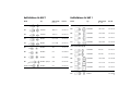
Heißluftdüsen für HAP 1
Modell Typ Abmessungen Best.-Nr.
A x B
2-seitig beheizt (Typ D)
D04 Heißluftdüse 10,5 x 10,5 5 87 277 79
D06 Heißluftdüse 13,0 x 10,0 5 87 277 82
D08 Heißluftdüse 15,0 x 10,0 5 87 277 81
D10 Heißluftdüse 18,0 x 10,0 5 87 277 84
alle 4 Seiten beheizt (Typ Q)
Q02 Heißluftdüse 6,0 x 6,5 5 87 277 77
Q04 Heißluftdüse 6,0 x 9,0 5 87 277 78
Q06 Heißluftdüse 15,0 x 10,0 5 87 277 80
Q08 Heißluftdüse 12,5 x 15,0 5 87 277 83
Q10 Heißluftdüse 18,0 x 18,0 5 87 277 85
R01 Meßdüse 5 87 278 08
Heißluftdüsen für HAP 1
Modell Typ Abmessungen Best.-Nr.
A x B
F02 Flachdüse 8,0 x 1,5 5 87 277 74
F04 Flachdüse 10,0 x 1,5 5 87 277 73
F06 Flachdüse 12,0 x 1,5 5 87 277 72
FD2 Dualdüse ø 1,5 x 8,0 5 87 277 76
FD4 Dualdüse ø 1,5 x 10,0 5 87 277 75
R02 Runddüse ø 0,8 5 87 271 16
R04 Runddüse ø 1,2 5 87 270 59
R06 Runddüse ø 3,0 5 87 270 60
R08 Runddüse, gebogen ø 2,0 5 87 277 86
R10 Runddüse ø 2,5 5 87 277 87

7
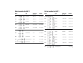
Hot air nozzles for HAP 1
Model Type Dimensions Order-No.
A x B
2-sides heated (Type D)
D04 Nozzle 10,5 x 10,5 5 87 277 79
D06 Nozzle 13,0 x 10,0 5 87 277 82
D08 Nozzle 15,0 x 10,0 5 87 277 81
D10 Nozzle 18,0 x 10,0 5 87 277 84
all 4 sides heated (Type Q)
Q02 Nozzle 6,0 x 6,5 5 87 277 77
Q04 Nozzle 6,0 x 9,0 5 87 277 78
Q06 Nozzle 15,0 x 10,0 5 87 277 80
Q08 Nozzle 12,5 x 15,0 5 87 277 83
Q10 Nozzle 18,0 x 18,0 5 87 277 85
R01 Measuring nozzle 5 87 278 08
Hot air nozzles for HAP 1
Model Type Dimensions Order-No.
A x B
F02 Flat nozzle 8,0 x 1,5 5 87 277 74
F04 Flat nozzle 10,0 x 1,5 5 87 277 73
F06 Flat nozzle 12,0 x 1,5 5 87 277 72
FD2 Dual nozzle ø 1,5 x 8,0 5 87 277 76
FD4 Dual nozzle ø 1,5 x 10,0 5 87 277 75
R02 Round nozzle ø 0,8 5 87 271 16
R04 Round nozzle ø 1,2 5 87 270 59
R06 Round nozzle ø 3,0 5 87 270 60
R08 Round nozzle, bent ø 2,0 5 87 277 86
R10 Round nozzle ø 2,5 5 87 277 87
-
 1
1
-
 2
2
-
 3
3
-
 4
4
-
 5
5
-
 6
6
-
 7
7
-
 8
8


Weller HAP 1 Operating Instructions Manual
- Tip
- Operating Instructions Manual
diğer dillerde
- français: Weller HAP 1
- italiano: Weller HAP 1
- Deutsch: Weller HAP 1
- English: Weller HAP 1
İlgili makaleler
-
Weller HAP 1 Operating Instructions Manual
-
Weller WAD 101 Operating Instructions Manual
-
-
-
-
-
-
-
-