
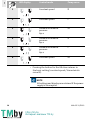
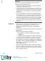
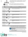
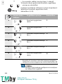
4 238 457-Ed.01 / 2019-12
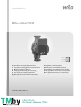
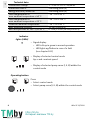
Wilo-Atmos PICO
Pioneering for You
en Installation and operating instructions
it Istruzioni di montaggio, uso e manutenzione
tr Montajvekullanmakılavuzu
el Οδηγίεςεγκατάστασηςκαιλειτουργίας
ro Instrucţiunidemontajşiexploatare
bg Инструкциязамонтажиексплоатация
et Paigaldus- ja kasutusjuhend
lt Montavimo ir naudojimo instrukcija
lv Uzstādīšanasunekspluatācijasinstrukcija
ru Инструкцияпомонтажуиэксплуатации
uk Iнструкціязмонтажутаексплуатації
https://tm.by
Интернет-магазин TM.by

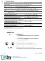
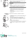
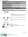
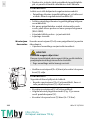
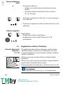
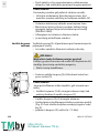
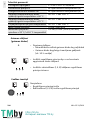
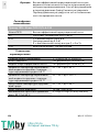
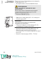
Fig. 1:
9
8
710
1 11
4
5
2
3
6
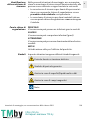
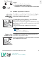
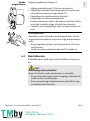
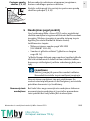
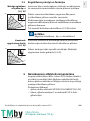
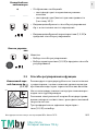
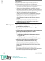
Fig. 2: Fig. 3a:
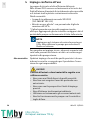
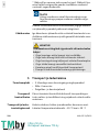
Fig. 3b:
PE NL
https://tm.by
Интернет-магазин TM.by

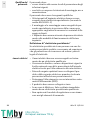
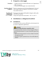
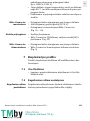
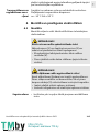
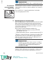
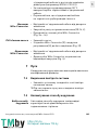
Fig. 3c:
Fig. 3d:
Fig. 3e:
Fig. 3f:
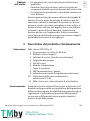
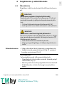
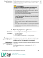
Fig. 4:
https://tm.by
Интернет-магазин TM.by

en Installation and operating instructions 4
it Istruzioni di montaggio, uso e manutenzione 20
tr Montaj ve kullanma kılavuzu 37
el Οδηγίες εγκατάστασης και λειτουργίας 53
ro Instrucţiuni de montaj şi exploatare 70
bg Инструкция за монтаж и експлоатация 86
et Paigaldus- ja kasutusjuhend 104
lt Montavimo ir naudojimo instrukcija 120
lv Uzstādīšanas un ekspluatācijas instrukcija 136
ru Инструкция по монтажу и эксплуатации 152
uk Інструкція з монтажу та експлуатації 171
https://tm.by
Интернет-магазин TM.by

https://tm.by
Интернет-магазин TM.by

4Wilo SE 12/2019
en
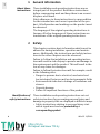
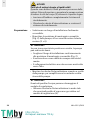
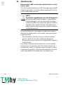
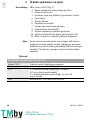
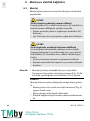
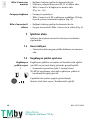
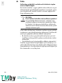
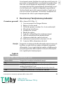
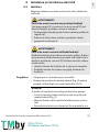
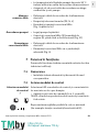
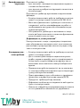
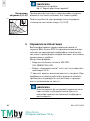
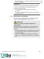
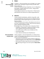
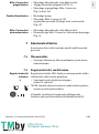
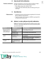
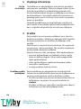
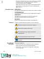
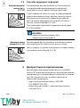
1 General information
About these
instructions These installation and operating instructions are an
integral part of the product. Read these instructions
before commencing work and keep them in an accessi-
ble place at all times.
Strict adherence to these instructions is a precondition
for the intended use and correct operation of the pro-
duct. All information and markings on the product must
be observed.
The language of the original operating instructions is
German. All other languages of these instructions are
translations of the original operating instructions.
2Safety
This chapter contains basic information which must be
adhered to during installation, operation and mainte-
nance. Additionally, the instructions and safety instruc-
tions in the other chapters must be observed.
Failure to follow the installation and operating instruc-
tions will result in risk of injury to persons and damage to
the environment and the product. This will result in the
loss of any claims for damages.
Failure to follow the instructions will, for example, result
in the following risks:
• Danger to persons due to electrical, mechanical and
bacteriological factors as well as electromagnetic fields
• Environmental risks due to leakage of hazardous sub-
stances
• Property damage
• Failure of important functions of the product
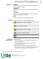
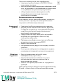
Identification of
safety instructions These installation and operating instructions set out
safety instructions for preventing personal injury and
damage to property that are displayed in different ways:
• Safety instructions relating to personal injury start
with a signal word and are preceded by a
corresponding symbol.
https://tm.by
Интернет-магазин TM.by

Installation and operating instructions Wilo-Atmos PICO 5
en
• Safety instructions relating to property damage start
with a signal word and are displayed
without
a symbol.
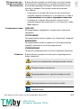
Signal words DANGER!
Failure to observe the safety instructions will result in
serious injuries or death!
WARNING!
Failure to follow the instructions can lead to (serious)
injuries!
CAUTION!
Failure to follow the instructions can lead to property
damage and a possible total loss.
NOTE
Useful information on handling the product.
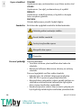
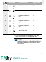
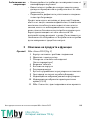
Symbols These instructions use the following symbols:
Personnel
qualifications Personnel must:
• Be instructed in the locally applicable accident pre-
vention regulations.
• Have read and understood the installation and
operating instructions.
Personnel must have the following qualifications:
• Electrical work must be carried out by an authorised
electrician (in accordance with EN 50110-1).
Danger due to electrical voltage
General danger symbol
Warning of hot surfaces/media
Warning of magnetic fields
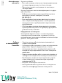
Notes
https://tm.by
Интернет-магазин TM.by

6Wilo SE 12/2019
en
• Installation/dismantling must be carried out by a
qualified technician who is trained in the use of the
necessary tools and mounting materials.
• The product must be operated by persons who are
instructed in the functioning of the complete system.
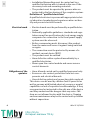
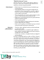
Definition of “qualified electrician”
A qualified electrician is a person with appropriate techni
-
cal education, knowledge and experience who can iden
-
tify and prevent electrical hazards.
Electrical work • Electrical work must be performed by a qualified elec-
trician.
• Nationally applicable guidelines, standards and regu-
lations as well as specifications by local energy supply
companies for connection to the local power supply
system must be observed.
• Before commencing work, disconnect the product
from the mains and secure it against being switched
on again.
• The connection must be protected by means of a
residual-current device (RCD).
• The product must be earthed.
• Have defective cables replaced immediately by a
qualified electrician.
• Never open the control module and never remove
control elements.
Obligations of the
operator • Have all work carried out by qualified personnel only.
• Ensure on-site contact protection from hot com-
ponents and electrical hazards.
• Have defective gaskets and connecting cables replaced.
This device can be used by children from 8 years old as
well as persons with limited physical, sensory or mental
capabilities or lack of experience and knowledge, if they
are supervised or instructed in the safe use of the device
and they understand the dangers that may arise. Chil-
dren are not allowed to play with the device. Cleaning
and user maintenance may not be carried out by children
without supervision.
https://tm.by
Интернет-магазин TM.by

Installation and operating instructions Wilo-Atmos PICO 7
en
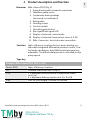
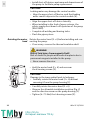
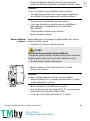
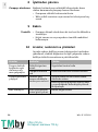
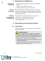
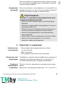
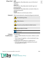
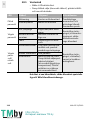
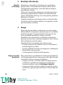
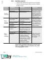
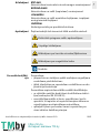
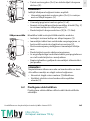
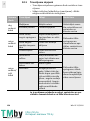
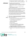
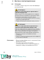
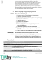
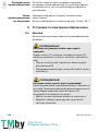
3 Product description and function
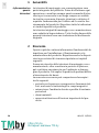
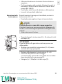
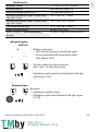
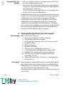
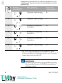
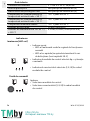
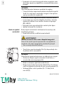
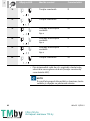
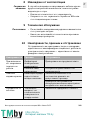
Overview Wilo-Atmos PICO (Fig. 1)
1 Pump housing with screwed connections
2 Glandless pump motor
3 Condensate drain openings
(4x around circumference)
4 Rating plate
5Housing screws
6 Control module
7 Operating push button
8 Run signal/fault signal LED
9 Display of selected control mode
10 Display of selected characteristic curve (I, II, III)
11 Wilo-Connector, electrical mains connection
Function High-efficiency circulator for hot-water heating sys-
tems with integrated differential pressure control. Con-
trol mode and delivery head (differential pressure) are
adjustable. The differential pressure is controlled via the
pump speed.
Type key
Example: Wilo-Atmos PICO 25/1-6-130
Atmos PICO High-efficiency circulator
25 Screwed connection DN 25 (Rp 1)
1-6 1 = Minimum delivery head in m (adjustable down
to 0.5 m)
6 = Maximum delivery head in m at Q = 0 m³/h
130 Port-to-port length: 130 mm or 180 mm
https://tm.by
Интернет-магазин TM.by

8Wilo SE 12/2019
en
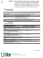
Technical data
Indicator
lights (LEDs)
•Signal display
• LED is lit up in green in normal operation
• LED lights up/flashes in case of a fault
(see chapter 10.1)
• Display of selected control mode
Δp-v and constant speed
• Display of selected pump curve (I, II, III) within the
control mode
Operating button
Press
•Select control mode
• Select pump curve (I, II, III) within the control mode
Connection voltage 1 ~ 230 V ± 10 %, 50/60 Hz
Protection class IP See rating plate (4)
Energy efficiency index EEI See rating plate (4)
Fluid temperatures at
max. ambient temperature +40 °C -10 °C to +95 °C
Fluid temperatures at
max. ambient temperature +25 °C -10 °C to +110 °C
Permitted ambient temperature -10 °C to +40 °C
Max. operating pressure 10 bar (1000 kPa)
Min. inlet pressure at +95 °C/+110 °C 0.3 bar/1.0 bar (30 kPa/100 kPa)
https://tm.by
Интернет-магазин TM.by

Installation and operating instructions Wilo-Atmos PICO 9
en
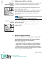
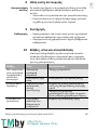
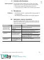
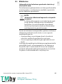
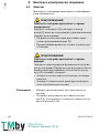
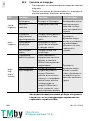
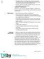
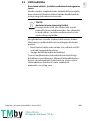
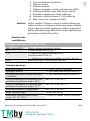
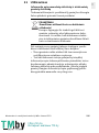
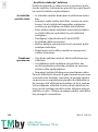
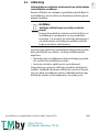
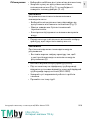
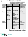
3.1 Control modes and functions
Variable differential
pressure
Δp-v
(I, II, III)
Recommended for two-pipe heating systems with radi-
ators to reduce the flow noise at thermostatic valves.
The pump reduces the delivery head to half in the case of
decreasing volume flow in the pipe network.
Electrical energy saving by adjusting the delivery head to
the volume flow requirement and lower flow rates.
There are three pre-defined pump curves (I, II, III) to
choose from.
Constant
speed (I, II, III) Recommended for systems with fixed system resistance
requiring a constant volume flow.
The pump runs in three prescribed fixed speed
stages (I, II, III).
4 Intended use
The high-efficiency circulators in the Wilo-Atmos PICO
series are exclusively designed for circulating fluids in
hot-water heating systems and similar systems with
constantly changing volume flows.
Permitted fluids:
• Heating water according to VDI 2035
(CH: SWKI BT 102-01).
• Water-glycol mixtures* with a maximum of 50 %
glycol.
* Glycol has a higher viscosity than water. If glycol is
added, the delivery data of the pump must be corrected
to suit the mixing ratio.
II
III
I
H/m
Q/m³/ h
NOTE
Factory setting:
Δp-v
, pump curve II
I
III
II
H/m
Q/m³/ h
https://tm.by
Интернет-магазин TM.by

10 Wilo SE 12/2019
en
Intended use includes observing these instructions and
the data and markings on the pump.
Misuse Any use beyond the intended use is considered misuse
and will result in the loss of all liability claims.
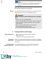
5 Transportation and storage
Scope of delivery • High-efficiency circulator with 2 gaskets
• Wilo-Connector
• Installation and operating instructions
Transport
inspection Inspect for transportation damage and check complete-
ness immediately after delivery, and claim immediately if
necessary.
Transport and
storage conditions Protect from moisture, frost and mechanical loads.
Permissible temperature range: -10 °C to +50 °C.
NOTE
Only add ready-to-use mixtures to the system.
Do not use the pump to mix the fluid in the
system.
WARNING!
Danger of injury or material damage due to improper
use!
• Never use non-specified fluids.
• Never allow unauthorised persons to perform work.
• Never operate the pump outside of the specified
limits of use.
• Never carry out unauthorised conversions.
• Use authorised accessories only.
• Never operate with phase angle control.
https://tm.by
Интернет-магазин TM.by

Installation and operating instructions Wilo-Atmos PICO 11
en
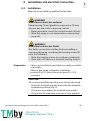
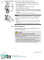
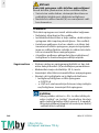
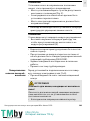
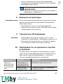
6 Installation and electrical connection
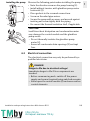
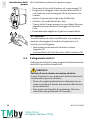
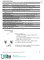
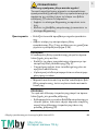
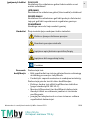
6.1 Installation
May only be installed by qualified technicians.
Preparation • Choose an installation point that is as easily accessible
as possible.
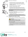
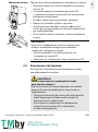
• Observe the pump's allowable installation
position (Fig. 2), rotate the motor head (2 + 6) if
necessary.
WARNING!
Risk of burns due to hot surfaces!
Pump housing (1) and glandless pump motor (2) may
become hot and result in burns on contact.
• During operation, touch the control module (6) only.
• Allow the pump to cool down before commencing
any work.
WARNING!
Risk of burns due to hot fluids!
Hot fluids can result in scalding. Before installing or
removing the pump, or undoing the housing screws (5),
note the following:
• Allow the heating system to cool down completely.
• Close shut-off devices or drain the heating system.
CAUTION!
An incorrect installation position may damage the pump.
• Select the installation point in line with the allowable
installation position (Fig. 2).
• The motor must always be installed horizontally.
• The electrical connection must never face upwards.
https://tm.by
Интернет-магазин TM.by

12 Wilo SE 12/2019
en
• Install shut-off devices upstream and downstream of
the pump to facilitate pump replacement.
• Align the upper shut-off device laterally.
• When installing in the feed of open systems, the
safety supply must branch off upstream of the pump
(EN 12828).
• Complete all welding and brazing tasks.
• Flush the pipe system.
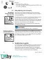
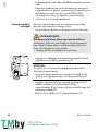
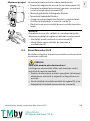
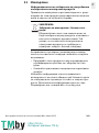
Rotating the motor
head Rotate the motor head (2 + 6) before installing and con-
necting the pump.
• If necessary, remove the thermal insulation shell.
• Hold the motor head (2 + 6) and unscrew
the 4 housing screws (5).
• Carefully rotate the motor head (2 + 6).
• Observe the allowable installation position (Fig. 2)
and the direction arrow on the pump housing (1).
• Tighten (4-7.5 Nm) the 4 housing screws (5).
CAUTION!
Leaking water may damage the control module.
• Align the upper shut-off device such that leaking
water cannot drip onto the control module (6).
WARNING!
Risk of fatal injury from magnetic field!
Risk of death for people with medical implants due to
permanent magnets installed in the pump.
• Never remove the rotor.
1
5
2
6
CAUTION!
Damage to the inner gasket leads to leakages.
• Carefully rotate the motor head (2 + 6) without
removing it from the pump housing (1).
https://tm.by
Интернет-магазин TM.by

Installation and operating instructions Wilo-Atmos PICO 13
en
Installing the pump Observe the following points when installing the pump:
• Note the direction arrow on the pump housing (1).
• Install without tension, with glandless pump motor
horizontal (2).
• Place gaskets in the screwed connections.
• Screw on threaded pipe unions.
• Secure the pump with an open-end wrench against
twisting and screw tightly with the piping
• Re-mount the thermal insulation shell, if applicable.
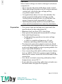
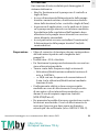
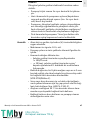
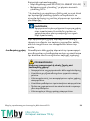
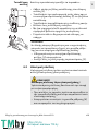
6.2 Electrical connection
The electrical connection may only be performed by a
qualified electrician.
1
2
3
CAUTION!
Insufficient heat dissipation and condensation water
may damage the control module and the glandless
pump motor.
• Do not thermally insulate the glandless pump
motor (2).
• Ensure all condensate drain openings (3) are kept
free.
DANGER!
Danger to life due to electrical voltage!
Immediate danger to life if live components are
touched.
• Before commencing work, switch off the power
supply and secure it against being switched on again.
• Never open the control module (6) and never remove
control elements.
https://tm.by
Интернет-магазин TM.by

14 Wilo SE 12/2019
en
Preparation • The current type and voltage must agree with the
specifications on the rating plate (4).
• Maximum back-up fuse: 10 A, slow-blow.
• Only operate the pump with sinusoidal AC voltage.
• Note switching frequency:
- On/off switching operations via mains voltage
≤ 100/24 h.
- ≤ 20/h for a switching frequency of 1 min.
between switching on/off via mains voltage.
• The electrical connection must be made via a fixed
connecting cable equipped with a connector device or
an all-pole switch with a contact opening width of at
least 3 mm (VDE 0700/Part 1).
• Use a connecting cable with a sufficient outer diame-
ter (e.g. H05VV-F3G1.5) to protect against leaking
water and to ensure strain relief at the threaded cable
connection.
• Use a heat-resistant connecting cable where fluid
temperatures exceed 90 °C.
• Ensure that the connecting cable does not make con-
tact with either the pipes or the pump.
CAUTION!
Pulsed mains voltage can lead to damage to electronic
components.
• Never operate the pump with phase angle control.
• When switching the pump on or off using an external
control unit, deactivate any voltage pulsing
(e.g. phase angle control).
• For applications where it is not clear whether the
pump is operated with pulsed voltage, get the
control/system manufacturer to confirm that the
pump is operated with sinusoidal AC voltage.
• Switching the pump on/off via triacs/solid-state
relays must be examined on a case-by-case basis.
https://tm.by
Интернет-магазин TM.by

Installation and operating instructions Wilo-Atmos PICO 15
en
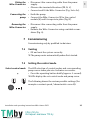
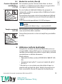
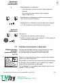
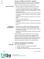
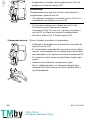
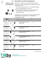
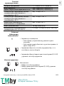
Fitting the
Wilo-Connector • Disconnect the connecting cable from the power
supply.
• Observe the terminal allocations (PE, N, L).
• Connect and fit the Wilo-Connector (Fig. 3a to 3e).
Connecting the
pump • Earth the pump.
• Connect the Wilo-Connector (9) to the control
module (6) until it snaps into place (Fig 3f).
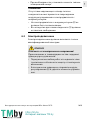
Removing the
Wilo-Connector • Disconnect the connecting cable from the power
supply.
• Remove the Wilo-Connector using a suitable screw-
driver (Fig. 4).
7 Commissioning
Commissioning only by qualified technicians.
7.1 Venting
• Fill and vent the system correctly.
The pump vents automatically when first started.
7.2 Setting the control mode
Select control mode The LED selection of control modes and corresponding
pump curves takes place in clockwise succession.
• Press the operating button briefly (approx. 1 second).
LEDs display the set control mode and pump curve.
The following shows the various possible settings (for
example: constant speed / characteristic curve III):
https://tm.by
Интернет-магазин TM.by

16 Wilo SE 12/2019
en
• Pressing the button for the 6th time returns to
the basic setting (constant speed / characteristic
curve III).
LED display Control mode Pump curve
1Constant speed II
2Constant speed I
3Variable differential
pressure
Δp-v
III
4Variable differential
pressure
Δp-v
II
5Variable differential
pressure
Δp-v
I
6Constant speed III
NOTE
All settings and displays are retained if the power
supply is interrupted.
https://tm.by
Интернет-магазин TM.by

Installation and operating instructions Wilo-Atmos PICO 17
en
8 Decommissioning
Shutting down the
pump Shut down the pump immediately in case of damage to
the connecting cable or other electrical components.
• Disconnect the pump from the power supply.
• Contact Wilo customer service or a specialist technician.
9 Maintenance
Cleaning • Carefully remove soiling from the pump on a regular
basis using a dry duster.
• Never use liquids or aggressive cleaning agents.
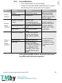
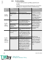
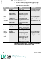
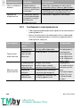
10 Faults, causes and remedies
The troubleshooting must only be performed by a
qualified specialist, work on the electrical connection
must only be performed by a qualified electrician.
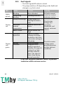
Faults Causes Remedies
Pump is not
running
although the
power supply is
switched on
Electrical fuse
defective Check fuses
Pump has no
voltage Resolve the power interruption
Pump making
noises Cavitation due to
insufficient suction
pressure
Increase the system pressure within
the permissible range
Check the delivery head and set it to
a lower head if necessary
Building does
not get warm Thermal output of
the heating
surfaces is too low
Increase setpoint
https://tm.by
Интернет-магазин TM.by

18 Wilo SE 12/2019
en
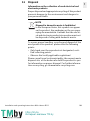
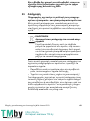
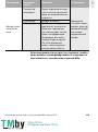
10.1 Fault signals
• The fault signal LED indicates a fault.
• The pump switches off (depending on the fault) and
attempts a cyclical restart.
If the fault cannot be remedied, contact a specialist
technician or Wilo customer service.
LED Faults Causes Remedy
Lights
up red
Blocking Rotor blocked Activate manual
restart or contact
customer service
Contacting/
winding Winding defective
Flashes
red
Under/overvoltage Power supply too
low/high on mains
side Check mains
voltage and
operating
conditions, and
request customer
service
Excessive
module
temperature
Module interior too
warm
Short-circuit Motor current too
high
Flashes
red/
green
Generator
operation Water is flowing
through the pump
hydraulics, but there
is no mains voltage at
the pump Check the mains
voltage, water
quantity/pressure
and the ambient
conditions
Dry run Air in the pump
Overload Sluggish motor,
pump is operated
outside of its specifi-
cations (e.g. high
module tempera-
ture). The speed is
lower than during
normal operation
https://tm.by
Интернет-магазин TM.by
Sayfa yükleniyor...
Sayfa yükleniyor...
Sayfa yükleniyor...
Sayfa yükleniyor...
Sayfa yükleniyor...
Sayfa yükleniyor...
Sayfa yükleniyor...
Sayfa yükleniyor...
Sayfa yükleniyor...
Sayfa yükleniyor...
Sayfa yükleniyor...
Sayfa yükleniyor...
Sayfa yükleniyor...
Sayfa yükleniyor...
Sayfa yükleniyor...
Sayfa yükleniyor...
Sayfa yükleniyor...
Sayfa yükleniyor...
Sayfa yükleniyor...
Sayfa yükleniyor...
Sayfa yükleniyor...
Sayfa yükleniyor...
Sayfa yükleniyor...
Sayfa yükleniyor...
Sayfa yükleniyor...
Sayfa yükleniyor...
Sayfa yükleniyor...
Sayfa yükleniyor...
Sayfa yükleniyor...
Sayfa yükleniyor...
Sayfa yükleniyor...
Sayfa yükleniyor...
Sayfa yükleniyor...
Sayfa yükleniyor...
Sayfa yükleniyor...
Sayfa yükleniyor...
Sayfa yükleniyor...
Sayfa yükleniyor...
Sayfa yükleniyor...
Sayfa yükleniyor...
Sayfa yükleniyor...
Sayfa yükleniyor...
Sayfa yükleniyor...
Sayfa yükleniyor...
Sayfa yükleniyor...
Sayfa yükleniyor...
Sayfa yükleniyor...
Sayfa yükleniyor...
Sayfa yükleniyor...
Sayfa yükleniyor...
Sayfa yükleniyor...
Sayfa yükleniyor...
Sayfa yükleniyor...
Sayfa yükleniyor...
Sayfa yükleniyor...
Sayfa yükleniyor...
Sayfa yükleniyor...
Sayfa yükleniyor...
Sayfa yükleniyor...
Sayfa yükleniyor...
Sayfa yükleniyor...
Sayfa yükleniyor...
Sayfa yükleniyor...
Sayfa yükleniyor...
Sayfa yükleniyor...
Sayfa yükleniyor...
Sayfa yükleniyor...
Sayfa yükleniyor...
Sayfa yükleniyor...
Sayfa yükleniyor...
Sayfa yükleniyor...
Sayfa yükleniyor...
Sayfa yükleniyor...
Sayfa yükleniyor...
Sayfa yükleniyor...
Sayfa yükleniyor...
Sayfa yükleniyor...
Sayfa yükleniyor...
Sayfa yükleniyor...
Sayfa yükleniyor...
Sayfa yükleniyor...
Sayfa yükleniyor...
Sayfa yükleniyor...
Sayfa yükleniyor...
Sayfa yükleniyor...
Sayfa yükleniyor...
Sayfa yükleniyor...
Sayfa yükleniyor...
Sayfa yükleniyor...
Sayfa yükleniyor...
Sayfa yükleniyor...
Sayfa yükleniyor...
Sayfa yükleniyor...
Sayfa yükleniyor...
Sayfa yükleniyor...
Sayfa yükleniyor...
Sayfa yükleniyor...
Sayfa yükleniyor...
Sayfa yükleniyor...
Sayfa yükleniyor...
Sayfa yükleniyor...
Sayfa yükleniyor...
Sayfa yükleniyor...
Sayfa yükleniyor...
Sayfa yükleniyor...
Sayfa yükleniyor...
Sayfa yükleniyor...
Sayfa yükleniyor...
Sayfa yükleniyor...
Sayfa yükleniyor...
Sayfa yükleniyor...
Sayfa yükleniyor...
Sayfa yükleniyor...
Sayfa yükleniyor...
Sayfa yükleniyor...
Sayfa yükleniyor...
Sayfa yükleniyor...
Sayfa yükleniyor...
Sayfa yükleniyor...
Sayfa yükleniyor...
Sayfa yükleniyor...
Sayfa yükleniyor...
Sayfa yükleniyor...
Sayfa yükleniyor...
Sayfa yükleniyor...
Sayfa yükleniyor...
Sayfa yükleniyor...
Sayfa yükleniyor...
Sayfa yükleniyor...
Sayfa yükleniyor...
Sayfa yükleniyor...
Sayfa yükleniyor...
Sayfa yükleniyor...
Sayfa yükleniyor...
Sayfa yükleniyor...
Sayfa yükleniyor...
Sayfa yükleniyor...
Sayfa yükleniyor...
Sayfa yükleniyor...
Sayfa yükleniyor...
Sayfa yükleniyor...
Sayfa yükleniyor...
Sayfa yükleniyor...
Sayfa yükleniyor...
Sayfa yükleniyor...
Sayfa yükleniyor...
Sayfa yükleniyor...
Sayfa yükleniyor...
Sayfa yükleniyor...
Sayfa yükleniyor...
Sayfa yükleniyor...
Sayfa yükleniyor...
Sayfa yükleniyor...
Sayfa yükleniyor...
Sayfa yükleniyor...
Sayfa yükleniyor...
Sayfa yükleniyor...
Sayfa yükleniyor...
Sayfa yükleniyor...
Sayfa yükleniyor...
Sayfa yükleniyor...
Sayfa yükleniyor...
Sayfa yükleniyor...
Sayfa yükleniyor...
Sayfa yükleniyor...
Sayfa yükleniyor...
Sayfa yükleniyor...
Sayfa yükleniyor...
Sayfa yükleniyor...
Sayfa yükleniyor...
Sayfa yükleniyor...
Sayfa yükleniyor...
Sayfa yükleniyor...
Sayfa yükleniyor...
Sayfa yükleniyor...
Sayfa yükleniyor...
Sayfa yükleniyor...
Sayfa yükleniyor...
-
 1
1
-
 2
2
-
 3
3
-
 4
4
-
 5
5
-
 6
6
-
 7
7
-
 8
8
-
 9
9
-
 10
10
-
 11
11
-
 12
12
-
 13
13
-
 14
14
-
 15
15
-
 16
16
-
 17
17
-
 18
18
-
 19
19
-
 20
20
-
 21
21
-
 22
22
-
 23
23
-
 24
24
-
 25
25
-
 26
26
-
 27
27
-
 28
28
-
 29
29
-
 30
30
-
 31
31
-
 32
32
-
 33
33
-
 34
34
-
 35
35
-
 36
36
-
 37
37
-
 38
38
-
 39
39
-
 40
40
-
 41
41
-
 42
42
-
 43
43
-
 44
44
-
 45
45
-
 46
46
-
 47
47
-
 48
48
-
 49
49
-
 50
50
-
 51
51
-
 52
52
-
 53
53
-
 54
54
-
 55
55
-
 56
56
-
 57
57
-
 58
58
-
 59
59
-
 60
60
-
 61
61
-
 62
62
-
 63
63
-
 64
64
-
 65
65
-
 66
66
-
 67
67
-
 68
68
-
 69
69
-
 70
70
-
 71
71
-
 72
72
-
 73
73
-
 74
74
-
 75
75
-
 76
76
-
 77
77
-
 78
78
-
 79
79
-
 80
80
-
 81
81
-
 82
82
-
 83
83
-
 84
84
-
 85
85
-
 86
86
-
 87
87
-
 88
88
-
 89
89
-
 90
90
-
 91
91
-
 92
92
-
 93
93
-
 94
94
-
 95
95
-
 96
96
-
 97
97
-
 98
98
-
 99
99
-
 100
100
-
 101
101
-
 102
102
-
 103
103
-
 104
104
-
 105
105
-
 106
106
-
 107
107
-
 108
108
-
 109
109
-
 110
110
-
 111
111
-
 112
112
-
 113
113
-
 114
114
-
 115
115
-
 116
116
-
 117
117
-
 118
118
-
 119
119
-
 120
120
-
 121
121
-
 122
122
-
 123
123
-
 124
124
-
 125
125
-
 126
126
-
 127
127
-
 128
128
-
 129
129
-
 130
130
-
 131
131
-
 132
132
-
 133
133
-
 134
134
-
 135
135
-
 136
136
-
 137
137
-
 138
138
-
 139
139
-
 140
140
-
 141
141
-
 142
142
-
 143
143
-
 144
144
-
 145
145
-
 146
146
-
 147
147
-
 148
148
-
 149
149
-
 150
150
-
 151
151
-
 152
152
-
 153
153
-
 154
154
-
 155
155
-
 156
156
-
 157
157
-
 158
158
-
 159
159
-
 160
160
-
 161
161
-
 162
162
-
 163
163
-
 164
164
-
 165
165
-
 166
166
-
 167
167
-
 168
168
-
 169
169
-
 170
170
-
 171
171
-
 172
172
-
 173
173
-
 174
174
-
 175
175
-
 176
176
-
 177
177
-
 178
178
-
 179
179
-
 180
180
-
 181
181
-
 182
182
-
 183
183
-
 184
184
-
 185
185
-
 186
186
-
 187
187
-
 188
188
-
 189
189
-
 190
190
-
 191
191
-
 192
192
-
 193
193
-
 194
194
-
 195
195
-
 196
196
-
 197
197
-
 198
198


