Monster Huma H4 V1.1 Gaming Laptop Kullanım kılavuzu
- Kategori
- Defterler
- Tip
- Kullanım kılavuzu

01
EN
H4 V4.1
USER MANUAL
BENUTZERHANDBUCH
KULLANIM KILAVUZU

02
EN DE
02
USER MANUAL
TABLE OF CONTENTS
Notice ..........................................................................................03
Preface ............................................................................ 03
1.1 Regulations Information ..................................................03
1.2 Safety Instructions ............................................................04
1.3 Conventions for this Manual ...........................................05
Getting to know the basics ............................................. 07
2.1 Product Specifcation ........................................................07
2.2 Preparing your Computer ................................................09
2.3 Product Overview ...............................................................10
Getting started ................................................................ 15
3.1 AC Adapter ...........................................................................15
3.2 Knowing the Keyboard ......................................................16
3.2.1 For keyboard users.........................................................16
3.3 Using the touchpad / clickpad ........................................18
3.3.1 Windows 10 Touchpad Usage ......................................19
BIOS-Setup ...................................................................... 19
4.1 About BIOS Setup...............................................................19
4.1.1 When to Use BIOS Setup ? ...........................................19
4.1.2 How to Run BIOS Setup ? .............................................20
4.2 BIOS Setup Menu ...............................................................20
4.2.1 Main Menu ........................................................................21
4.2.2 Advanced Menu ...............................................................22
4.2.3 Security Menu .................................................................23
4.2.4 Boot Menu ........................................................................24
4.2.5 Exit Menu ..........................................................................24
H4 V4.1

03
EN
The information in this user’s manual is protected by copyright laws, all parts of this
manual, including the products and software described in it, can not be reproduced,
transmitted, transcribed, stored in a retrieval system, nor translated into any lan-
guage.
THE MANUFACTURER OR RESELLER SHALL NOT BE LIABLE FOR ERRORS OR OMIS-
SIONS CONTAINED IN THIS MANUAL AND SHALL NOT BE LIABLE FOR ANY CONSE-
QUENTIAL DAMAGES, WHICH MAY RESULT FROM THE PERFORMANCE OR USE OF THIS
MANUAL.
The illustrations in this user’s manual are for reference only. Actual product specifi-
cations may vary with territories. The information in this user’s manual is subject to
change without notice.
Chapter 1
1.1 Regulations Information
NOTICE
Preface
• CE compliance
This device is classed as a technical information equipment (ITE) in class B
and is intended for use in living room and ofce. The CE-mark approves the
conformity by the EU-guidelines:
- EMC Directive 2014/30/EU,
- Low Voltage Directive 2014/35/EU(equals A2 : 2013),
- RF Directive 2014/53/ EU
SAR/DAS refers to the rate at which the body absorbs RF energy. The SAR limit
set by the ICNIRP Guidelines is 2.0 W/kg(10g).
Testing for SAR is conducted using standard operating positions accepted by
the EN standard.
During testing, the radio is set to its highest transmission levels and placed in
positions that simulate use against the body.
This product is compliant with ICNIRP Guidelines with respect to
Electromagnetic Fields (EMF) which specifies a Specific Absorption Rate (SAR)
limit of 2W/kg. DAS*/SAR: 1.9W/kg (corps/body)

04
EN
The unit can be operated at an ambient temperature of max. 35°C (95°F). Do
not subject it to temperatures below 5°C (41°F) or above 40°C (104 °F).
CAUTION: RISK OF EXPLOSION IF BATTERY IS REPLACED BY AN INCORRECT
TYPE DISPOSE OF USED BATTERIES ACCORDING TO THE INSTRUCTIONS.
Rechargeable Battery Notice
Do not
1.Throw into fire or a hot oven, or mechanically crush or cutting of a BATTERY
2.Throw or immerse into water 3.Heat to more than 60°C 4.Repaire or disassemble
5.Leave in an extremely low air pressure environment
6.Leave in an extremely high-temperature environment
A power cord is connected to a socket-outlet with earthing connection.
PREVENTION OF HEARING LOSS
CAUTION: Listening to music at high volume levels and for extended durations
can damage one’s hearing. In order to reduce the risk of damage to hearing,
one should lower the volume to a safe, comfortable level, and reduce the
amount of time listening at high levels. Headsets should comply with EN
50332-2 requirements.
FCC Information
FEDERAL COMMUNICATIONS COMMISSION INTERFERENCE STATEMENT
This equipment has been tested and found to comply with the limits for a Class
B digital device, pursuant to part 15 of the FCC Rules. These limits are designed
to provide reasonable protection against harmful interference in a residential
installation. This equipment generates, uses and can radiate radio frequency
energy and, if not installed and used in accordance with the instructions, may
cause harmful interference to radio communications. However, there is no guar-
antee that interference will not occur in a particular installation. If this equip-
ment does cause harmful interference to radio or television reception, which
can be determined by turning the equipment off and on, the user is encouraged
to try to correct the interference by one or more of the following measures:
-Reorient or relocate the receiving antenna.
-Increase the separation between the equipment and receiver.
-Connect the equipment into an outlet on a circuit different from that to which
the receiver is connected.
-Consult the dealer or an experienced radio/TV technician for help.

05
EN
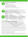
RF Exposure Information (SAR)
This device meets the government’s requirements for exposure to
radio waves. This device is designed and manufactured not to exceed
the emission limits for exposure to radio frequency (RF) energy set by
the Federal Communications Commission of the U.S. Government.
The exposure standard employs a unit of measurement known as the
Specific Absorption Rate, or SAR. The SAR limit set by the FCC is 1.6
W/kg. Tests for SAR are conducted using standard operating positions
accepted by the FCC with the EUT transmitting at the specified power
level in different channels.
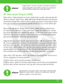
The FCC has granted an Equipment Authorization for this device with
all reported SAR levels evaluated as in compliance with the FCC RF
exposure guidelines. SAR information on this device is on file with the
FCC and can be found under the Display Grant section of www.fcc.gov/
eot/ea/fccid after searching on FCC ID: 2AKHFAX201NG .
This device complies with Part 15 of the FCC Rules. Operation is
subject to the following two conditions:
(1) this device may not cause harmful interference, and
(2) this device must accept any interference received, including
interference that may cause undesired operation.
Any changes or modifications not expressly
approved by the grantee of this device could void
the user’s authority to operate the equipment.
CAUTION:

06
EN
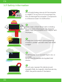
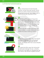
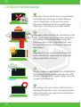
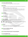
1.2 Safety Information
Do not apply heavy pressure to the computer
or subject it to any form of strong impact as
this can damage the computer’s components
or otherwise cause it to malfunction.
1
Never cover or block the air vents including
those located at the base of the computer.
Never cover your computer or AC adaptor with
any object.
2
Do NOT expose to or use near liquid, rain, or
moisture.
Do NOT use the modem during electrical
storms.
4
Do not use or expose this device around
magnetic felds as magnetic interference may
affect the performance of the device.
5
To keep your computer in prime operating
condition, protect your work area from direct
sunlight.
3

07
EN
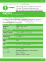
1.3 Conventions For This Manual
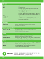
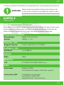
2.1 Product Specification
This message contains important information
that must be followed for safe operation.
CAUTION:
NOTE: This message contains information for special situations.
CHAPTER 2
Getting To Know The Basics
This User’s Manual provides technical information of instructions and illustra-
tions on how to operate this notebook for the customer. Please read this manu-
al carefully before using this notebook.
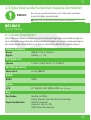
Physical Characteristic
Processor - CPU
Graphic Card - GPU
Dimension 308.8 x 213 x 15.6mm
Support Processor 11 Gen. Intel® Core™ i7-1165G7
Graphic Card Iris Xe (96EU)
Weight 0,99kg +/- %5
DDR4 DDR4
Memory
Audio
Display
Audio Codec Realtek ALC256
Azalia Standard-Support, D3 mode support
Speaker /MIC Built-in 2 speakers
Speakers: 2 W each
Digital microphone support
LCD 14” WUXGA FHD 1920x1200 Narrow Bazel

08
EN
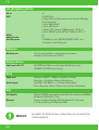
MODEL IS DESIGNED TO USE WITH THE DC
INPUT: 65 Watts , (19V/3.42A)
CAUTION:
I/O Port
Input
Communication Port
Power
Keyboard Membrane KB:277*106mm ,Travel=1.2mm
Backlight = Single zone /White Lighting
Pointing Device Outline/PCB: 130*80mm +/- 0.1mm /Glass Enable/Disable
area :10mm*10mm Palm Rejection:Support
Wireless LAN +BT M.2 2230 w/ CNVI interface (Intel WiFi6 AX series)
IEEE802.11AX201mode support
AC Adapter Automatics Voltage adjustment between 100 and 240VAC
50/60Hz, 65 Watts (19V/3.42A), 3 Pins
Battery Li- polymer Battery, SW Gas Gauge IC, soft pack,
1. 3cells (3s1p/4570mAh) 53Wh
DC-In x1
USB x2 USB Type A
x1 Right: (Gen1) (Power off mode support USB
power, & w/bc1.2 protocol )
x1 Left: (Gen1)
x1 Left:USB Type C:
x1 Right: TBT4 (only w/ 5V@3A output ) +W Type-C
x1 Left: USB3.1 gen2 /W Type-C Adaptor /w DP 1.4
HDMI x1
Audio Combo x1
Card Reader x1 USB3 interface, SD/SDHC/SDXC, UHS-I speed
Connecter: Full SD size
Webcam
HD webcam Infrared capability for facial reconition camera
IR Camera w/ D-MIC*2

09
EN
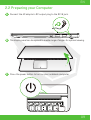
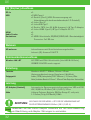
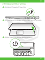
2.2 Preparing your Computer
AConnect the AC adaptor’s DC output plug to the DC IN jack.
BThe display panel can be opened to a wide range of angles for optimal viewing.
CPress the power button to turn on your notebook computer.

10
EN
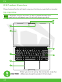
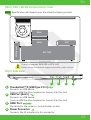
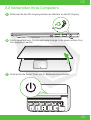
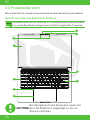
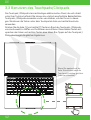
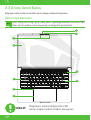
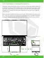
2.3 Product Overview
Please become familiar with each component before you operate the computer.
Top-Open View
The product’s color/ LED color, I/O port, indicator location, and
specification will depend upon the actually shipping product.
When you are not using the computer, keep the
LCDscreen closed to protect it from dust.
CAUTION:
NOTE
5
6
1
2
3
4
7
8
9

11
EN
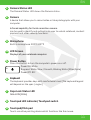
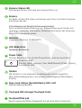
1Camera Status LED
The Camera Status LED shows the Camera status.
2Camera
A device that allows you to record video or take photographs with your
computer.
Infrared capability for facial reconition camera
can be used to identify and authenticate user to unlock notebook, conduct
payment and other security functions.
3Microphone
Built-in microphone IR CCD MIC*2
4LCD Screen
Displays of your notebook computer.
6Keyboard
The keyboard provides keys with comfortable travel (The keyboard legend
will depend on the spec / region)
7Caps Lock Status LED
Default: ON (White)
8Touchpad LED indicator/ Touchpad switch
9Touchpad/Click pad
Touch-sensitive pointing device which functions like the mouse.
5Power Button
Press this button to turn the computer’s power on or off.
Power ON: White
Suspend: White, Slow / Smooth, Blinking White (3Sec/Cycle)
Power Off: OFF

12
EN
To reduce the possibility of heat-related injuries or of overheating
the computer, do not place the computer directly on your lap or
obstruct the computer air vents. Use the computer only on a hard,
flat surface. Do not allow another hard surface, such as an
adjoining optional printer, or a soft surface, such as pillows or rugs
or clothing, to block airflow. Also, do not allow the AC adapter to
come into contact with the skin or a soft surface, such as pillows or
rugs or clothing, during operation.
CAUTION:
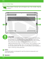
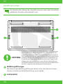
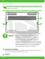
2
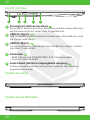
Vents
The thermal vents are designed to cool the internal components and
avoid overheating.
1
Speakers
Bottom Side View
The product’s thermal vent will depend upon the actually shipping
product.
NOTE
1
2
2

13
EN
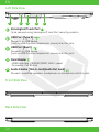
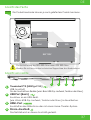
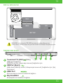
RAM / SSD / WLAN Compartment View
Right Side View
If need to upgrade SATA SSD to PCIE SSD,
Please contact technical support and after-sales service .
1Thunderbolt™4 (USB Type C 3.1)
Connects an USB device.
(such as USB Zip drive, keyboard or mouse) into this jack.
2USB Port (Gen1)
Connects an USB device.
(such as USB Zip drive, keyboard or mouse) into this jack.
3
3
HDMI Port
Connected to the screen, or home theater system.
Power Connector
Connects the AC adapter into this connector.
SSD(Option)
RAM
RAM
BATTERY
SSD
Specification will depend upon the actually shipping product.
NOTE
1 2 3 4

14
EN
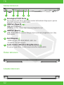
Left Side View
Front Side View
Back Side View
2USB Port (Type C)
Connects an USB device.
(such as USB Zip drive, keyboard or mouse) into this jack.
3USB Port (Gen1)
Connects an USB device.
(such as USB Zip drive, keyboard or mouse) into this jack.
5Audio Combo ( Mic In Jack/Audio Out Jack)
Connects amplified speakers, headphones or microphone into this jack.
1Kensington® Lock Port
To be secured using Kensington® Lock Port security products.
4Card Reader
-USB3 interface, SD/SDHC/SDXC, UHS-I speed
-Connecter: Full SD size
1 2 3 4 5

15
EN
CHAPTER 3
Getting Started
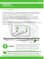
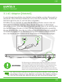
3.1 AC Adapter
Please be noted that it is strongly recommended to connect the AC adapter
and use the AC power while using this notebook for the first time. When the AC
adapter is connected, the battery is being charged immediately.
Attach the AC adapter when you need to charge the battery or you want to
operate from AC power. It is also the fastest way to get started, because the
battery pack will need to be charged before you can operate from battery
power.
Note that the AC adapter included in the package is approved for your
notebook; using other adapter model may damage either the notebook or other
devices attached to it.
The use of inferior extension cords may result in damage to
your notebook. Your notebook comes with its own
authorized AC adapter. Use of a different AC adapter or
cable extension which is not authorized for use will void
warranty protection if damage to hardware is found in
association to said adapter or extension cable.
CAUTION:
The power adapter can become hot when in use. Please be sure the AC
adapter is not covered with any materials keep it away from exposed parts of
your body. The AC adapter appearance may vary depending on your region.
NOTE
DC IN

16
EN
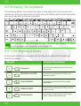
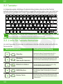
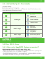
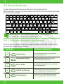
3.2 Knowing The Keyboard
3.2.1 For Keyboard Users
The following defnes the colored hot keys on the Keyboard. The colored com-
mands can only be accessed by frst pressing and holding the function key while
pressing a key with a colored command.
To activate these functions, press the hot key associated with the desired
function as below:
The number of keys available on your keyboard will depend on which
country/region your computer is confgured for.
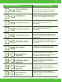
Suspend: Press this key combination (Fn+F1) to enter
sleep mode.
Press this key combination (Fn+F2) to turn
Windows Lock/On .
Press this key combination (Fn+F3) to enable
Display Mode.
Press this key combination (Fn+F4) to turn all
radios on or off.
Press this key combination (Fn+F5) to quick
switch - Basic mode / Silent mode.
Windows Lock/On:
Display Mode:
RADIO On/Off:
Mode Switch:
Keypad Function Description
NOTE

17
EN
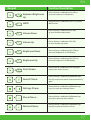
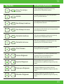
Keyboard Brightness
Up:
Press this key combination (Fn+F6) to
increase brightness of Keyboard.
Press this key combination (Fn+F7) to enter
MUTE mode.
Press this key combination (Fn+F8)
to enter Volume down mode.
Press this key combination (Fn+F9)
to enter Volume up mode.
Press this key combination (Fn+F10) to
decrease brightness of LCD display.
Press this key combination (Fn+F11) to
increase brightness of LCD display.
Press this key combination (Fn+F12) will
capture the entire screen.
Press this key combination (Windows logo
key+Q) to open the search charm and search
apps.
Press this key combination (Windows logo
key+I) to open the settings charm.
Press this key combination (Windows logo
key+H) to open the share charm.
Press this key combination (Windows logo
key+K) to open the devices charm.
MUTE:
Volume Down:
Volume Up:
Brightness Down:
Brightness Up:
Print Screen:
Search Charm:
Settings Charm
Share Charm :
Devices Charm:
Keypad Function Description

18
EN
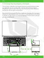
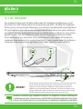
3.3 Using the touchpad / clickpad
The touchpad / clickpad is a rectangular electronic panel located just below
your keyboard. You can use the static-sensitive panel of the touchpad /
clickpad and slide it to move the cursor. You can use the buttons below the
touchpad as left and right mouse buttons.
Press the left (1) and right (2) buttons located on the edge of the touchpad /
clickpad to make selections and run functions. These two buttons are similar
to the left and right buttons on a mouse. Tapping on the touchpad / clickpad
produces similar results.
Click twice will open or close
touchpad functionality
12
12

19
EN
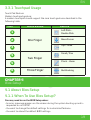
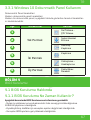
3.3.1 Touchpad Usage
Touch Pad Gesture
Modern touchpad gesture:
A modern touchpad should support the core touch gestures described in the
following table.
Gesture Name
Item Gesture
1
2
3
4
5
6
One Finger
Left Click -
Double Click
Move Cursor
Tap + Slide
Scroll / Pan
Pinch - Zoom
Multitasking
Two Finger
Three Finger
CHAPTER 4
Bios Setup
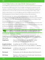
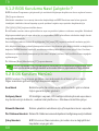
4.1 About Bios Setup
4.1.1 When To Use Bios Setup?
You may need to run the BIOS Setup when:
• An error message appears on the screen during the system booting up and is
requested to run SETUP.
• You want to change the default settings for customized features.
• You want to reload the default BIOS settings.

20
EN
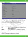
4.2 BIOS Setup Menu
4.1.2 How to Run BIOS Setup?
To run the BIOS Setup Utility, turn on the notebook and press the [Del] key during
the POST procedure.
If the message disappears before you respond and you still wish to enter Setup,
either restart the system by turning it OFF and ON, or simultaneously pressing
[Ctrl]+[Alt]+[Del] keys to restart.
Be noted that the screen snaps and setting options in this chapter are for your
references only.The actual setting screens and options on your Notebook may be
different because of BIOS update.
The setup function only can be invoked by pressing [Del] or [F2] key during POST
that provide a approach to change some setting and confguration the user pre-
fer, and the changed values will save in the NVRAM and will take effect after the
system rebooted. The setup uses a menu interface to allow the user to confgure
their system and the features are briefly listed as follow.
Press [F7] key for Boot Menu.
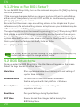
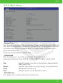
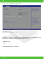
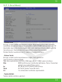
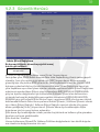
Once you enter the BIOS Setup Utility, the Main Menu will appear on the screen.
Select the tags to enter the other menus.
Main Menu Show system overview about memory size and setting of
system time and date.
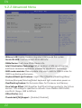
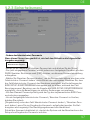
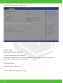
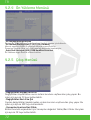
Advanced Menu To select the XD feature enable or disable XD
feature only work with Intel platform + Windows.
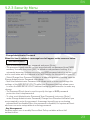
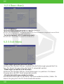
Security Menu Install or clear the password settings for
supervisor and user.
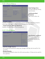
Boot Menu Confgure Settings during System Boot.
EXIT Menu Save or discard the changes before leaving the
BIOS Setup Menu.
The drivers, BIOS and utilities bundled in the support DVD may vary by
models and are subject to change without notice.
NOTE
Sayfa yükleniyor ...
Sayfa yükleniyor ...
Sayfa yükleniyor ...
Sayfa yükleniyor ...
Sayfa yükleniyor ...
Sayfa yükleniyor ...
Sayfa yükleniyor ...
Sayfa yükleniyor ...
Sayfa yükleniyor ...
Sayfa yükleniyor ...
Sayfa yükleniyor ...
Sayfa yükleniyor ...
Sayfa yükleniyor ...
Sayfa yükleniyor ...
Sayfa yükleniyor ...
Sayfa yükleniyor ...
Sayfa yükleniyor ...
Sayfa yükleniyor ...
Sayfa yükleniyor ...
Sayfa yükleniyor ...
Sayfa yükleniyor ...
Sayfa yükleniyor ...
Sayfa yükleniyor ...
Sayfa yükleniyor ...
Sayfa yükleniyor ...
Sayfa yükleniyor ...
Sayfa yükleniyor ...
Sayfa yükleniyor ...
Sayfa yükleniyor ...
Sayfa yükleniyor ...
Sayfa yükleniyor ...
Sayfa yükleniyor ...
Sayfa yükleniyor ...
Sayfa yükleniyor ...
Sayfa yükleniyor ...
Sayfa yükleniyor ...
Sayfa yükleniyor ...
Sayfa yükleniyor ...
Sayfa yükleniyor ...
Sayfa yükleniyor ...
Sayfa yükleniyor ...
Sayfa yükleniyor ...
Sayfa yükleniyor ...
Sayfa yükleniyor ...
Sayfa yükleniyor ...
Sayfa yükleniyor ...
Sayfa yükleniyor ...
Sayfa yükleniyor ...
Sayfa yükleniyor ...
Sayfa yükleniyor ...
Sayfa yükleniyor ...
Sayfa yükleniyor ...
Sayfa yükleniyor ...
-
 1
1
-
 2
2
-
 3
3
-
 4
4
-
 5
5
-
 6
6
-
 7
7
-
 8
8
-
 9
9
-
 10
10
-
 11
11
-
 12
12
-
 13
13
-
 14
14
-
 15
15
-
 16
16
-
 17
17
-
 18
18
-
 19
19
-
 20
20
-
 21
21
-
 22
22
-
 23
23
-
 24
24
-
 25
25
-
 26
26
-
 27
27
-
 28
28
-
 29
29
-
 30
30
-
 31
31
-
 32
32
-
 33
33
-
 34
34
-
 35
35
-
 36
36
-
 37
37
-
 38
38
-
 39
39
-
 40
40
-
 41
41
-
 42
42
-
 43
43
-
 44
44
-
 45
45
-
 46
46
-
 47
47
-
 48
48
-
 49
49
-
 50
50
-
 51
51
-
 52
52
-
 53
53
-
 54
54
-
 55
55
-
 56
56
-
 57
57
-
 58
58
-
 59
59
-
 60
60
-
 61
61
-
 62
62
-
 63
63
-
 64
64
-
 65
65
-
 66
66
-
 67
67
-
 68
68
-
 69
69
-
 70
70
-
 71
71
-
 72
72
-
 73
73


Monster Huma H4 V1.1 Gaming Laptop Kullanım kılavuzu
- Kategori
- Defterler
- Tip
- Kullanım kılavuzu